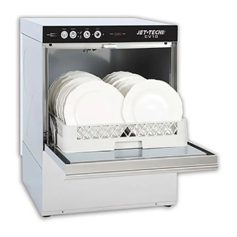
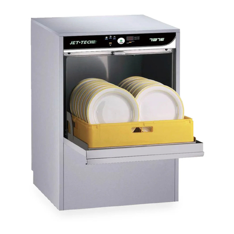
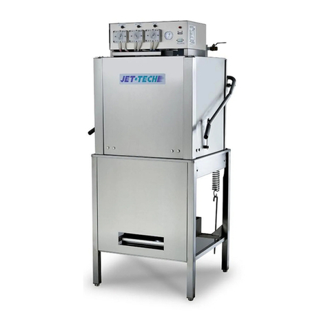
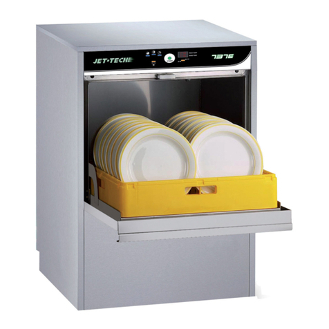
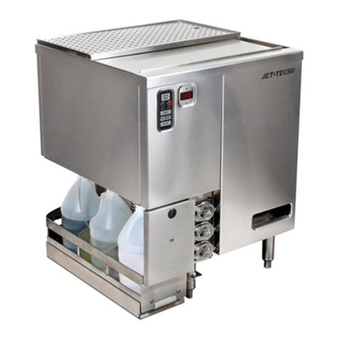
Jet-tech 757E User manual

OWNER’S MANUAL
DISHWASHER INSTALLATION AND MAINTENANCE
Model
757E
For operator. Do not discard.
2017 02
REV 001

1 888 275 4538 MVP GROUP .2 | P a g e
INDEX
1 - GENERAL RECCOMMENDATIONS .………………...……………………... p.3
1A - HANDLING ……………………………………………………………...…... p.3
1B - UNPACKING …………….………………………………….……………….. p.4
1C - DISPOSAL …………………………………….……………………………... p.4
1D –TECHNICAL DATA …………………………………..…………………….... p.4
2 - INSTALLER AND MAINTENANCE PERSON INSTRUCTIONS ……...…...... p.6
2A - WATER CONNECTION ……………………….………………………............. p.6
2B - ELECTRICAL CONNECTION …………….………………………….……...… p.8
2C –N/A
2D - DETERGENT AND RINSE AID DISPENSERS AND SETTINGS …….……........... p.8
2E - MANTEINANCE ………………………………………....………………........ p.10
2F - UNINSTALL (long period of inactivity)……….............…….……………........ p.10
3 - USER INSTRUCTIONS ……………..…..………………………………...... p.11
3A - GENERAL RECCOMENDATIONS AND WARRANTY ……….………............... p.11
3B - STARTING / WASH CYCLES (ELECTRONIC version) …………………............... p.13
3C –N/A
3D - DAILY CLEANNING / END OF WORK ……….....................………………....... p.19
3E –N/A
3F - WARNING MESSAGES DISPLAYED ON THE CONTROL PANEL …………..... p.20
4 - TROUBLESHOOTING …………………....……………………….……..... p.23
5 –MANUFACTURERS LIMITED WARRANTY…………………………… p.25
MVPGROUP CORPORATION
JET-TECH SYSTEMS
5659 Royalmount Avenue
Montreal, Quebec H4P 2P9
Tel.:
888
-275-4538 (888-ASK-4-JET); 514-737-9701
Fax: 877-452-8832; 514-737-2792
E-mail:
service@mvpgroupcorp.c
om

1 - GENERAL RECOMMENDATIONS
ATTENTION
Carefully read this instructions booklet, as it contains important advice for safe installation, operation and
maintenance. Keep this booklet to hand in a safe place for future reference by other operators.
Installation, use and service of the machine can be performed only by qualified personnel, especially trained
to follow instructions:
WARNING!
The manufacturer cannot be held responsible for injuries or damages of any kind occurred to persons,
machine or others, due to lack of conformity with the operation instructions indicated in this
documentation and for abuse, misuse and lack of conformity with the instructions indicated in this
documentation as well as installation, uninstall, service, tune-up, maintenance requiring the removal of
the safety barriers not performed BY TRAINED AND AUTHORIZED SPECIALISTS, will result in the
IMMEDIATE LOSS OF THE WARRANTY.
Loss of warranty will result also from any service performed to the machine, when: Safety barriers are
removed without disconnecting the power line and the water supply. When any safety provision of the
machine has been bypassed, removed or excluded.
Machine is installed in provisional, improper or unsafe conditions for lack of compliance with safety
provisions (fuses, main breaker, ground line, or water inlet and discharge valves).
When unauthorized modifications or additions of devices which modify the operation cycles indicated on
the data chart delivered with the machine.
When not genuine spare parts are used.
Installation or storage in inadequate spaces according to the indications of manufacturer.
Machine utilization different from the scope foreseen as written in the documentation (ex. Dishes of type
or sizes different from specified).
Utilization of chemical dispensers with corrosive products (Chlorinated), not pure or dry.
1A –HANDLING
Use suitable means to move the appliance: a lift truck or fork pallet trucks (the forks should reach more
than halfway beneath the appliance). This machine weights 140 Kg (308 lbs). It is recommended to move
this unit with two persons or more to avoid injuries.
1 888 275 4538 MVP GROUP .4 | P a g e
1B –UNPACKING
Before opening the boxes, verify the conditions and in case indicates damages on delivery slip. After
unpacking, check the machine conditions, in case the machine is damaged, communicate immediately to
the dealer.
Do not proceed with the installation if damages are relevant to operate safely and wait for qualified and
authorized assistance person. Keep packaging (boxing components such as plastic bags, expanded
polystyrene, nails, etc.) outside the reach of children for safety reasons.
1- Wear protective gloves to unpack the appliance from the packaging.
2- Lift the appliance using a lift truck.
3- Remove the protection film of the appliance.
1C –DISPOSAL
This appliance is marked according to the European directive 2002/96/EC on Waste Electrical and Electronic
Equipment (WEEE). By ensuring this product is disposed of correctly, you will help prevent potential
negative consequences for the environment and human health, which could otherwise be caused by
inappropriate waste handling of this product.
The symbol: on the product, or on the documents accompanying the product, indicates that
this appliance may not be treated as household waste. Instead it shall be handed over to the applicable
collection point for the recycling of electrical and electronic equipment. Disposal must be carried out in
accordance with local environmental regulations for waste disposal.
For more detailed information about treatment, recovery and recycling of this product, please contact your
local city office, your household waste disposal service or the store where you purchased the product.
1D –TECHNICAL DATA
WATER CONNECTION
Temperature
°C
50
°F
122
Pressure
kPA
200 - 500
Bar
2 - 5
PSI
29 - 72
Flow
Lt/min
20 - 30
Hardness
°f
7 –14

1 888 275 4538 MVP GROUP .5 | P a g e
°dH
4 - 7,5
°e
5 - 9,5
ppm
70 - 140
Mineral residues
mg/l
300 / 400
Conductivity
μS/cm
300 / 400
ELECTRICAL CONNECTION
Voltage
V
225 ± 6
%
Frequency
Hz
60 ± 1 %
Wash Cycle
°C
55
°F
131
Rinse Cycle
°C
85
°F
185
INSTALLATION ENVIRONMENT
Operating Temperature
°C
5 - 35
°F
41 - 95
Storage Temperature
°C
10 - 70
°F
50 - 158
1D1–NOISE LEVEL
Environment noise level cannot exceed the values as per Standards of place of installation. The noise of the
machine, measured at the manufacturer site, has been less than 70dB, approximately 58dB. When using the
machine following data must be complied with the storage, transportation, utilization and maintenance of
the machine. Values of this documentation can be updated according to the update and manufacturer can
reserve the rights to modify present values.

1 888 275 4538 MVP GROUP .6 | P a g e
2 - INSTALLER AND MAINTENANCE PERSON INSTRUCTIONS
ATTENTION
Specialists that install the machine are foreseen to train the operators about machine utilization and safety
procedures to be followed. They must provide a real “demonstration” and verify that machine instructions
are available to the operators.
Following attentions should be taken:
WARNING!
DO NOT OPEN THE DOOR QUICKLY IF CYCLE IS NOT ENDED.
DO NOT DIP BARE HANDS IN WASHING SOLUTION.
DO NOT TAKE OFF THE MACHINE PANELS IF THE MACHINE HAS NOT BEEN DISCONNECTED FROM THE
POWER AND WATER SUPPLY.
DO NOT BYPASS THE MACHINE PROTECTIONS (MICROSWITCHES, PANELS, OR OTHERS)
PROVIDED BY THE MACHINE MANUFACTURER IF NOT AT THE PRESENCE OF TRAINED SPECIALISTS THAT
CAN TAKE PROPRER PRECAUTIONS.
DO NOT UTILISE THE MACHINE TO WASH GOODS OUTSIDE THE SCOPE FOR WHICH IS PROVIDED FOR,
OBJECTS OF SHAPE, TYPE, SIZE, AND MATERIAL NOT COMPATIBLE.
DO NOT OPERATE THE MACHINE IF NOT PROPERLY CONNECTED, ACCORDING TO THE SPECIFICATIONS
AND REQUIREMENTS OF THE LOCAL LAW AND PRESCRIPTION OF MANUFACTURER, MAKING SURE THAT
ALL SAFETY DEVICES ARE OPERATIVE.
ID/RATING/DATA PLATE
ID/Rating plate of the appliance contains identification and technical data and is located on the front inside
panel.
- To remove the front panel: Unscrew the two screws located on the bottom of the panel.
2A –WATER CONNECTION
N.B.
Shut-off valve is a single direction, diaphragm control type, which can shut water supply off quickly and
totally. Selected to assure water pressure and flow as requested in the data diagram supplied with each
machine.
1- Position the dishwasher to its final location and level the appliance by turning the relative height
adjustable feet. (Fig.5)

1 888 275 4538 MVP GROUP .7 | P a g e
Fig. 5
2- Connect the solenoid valve, which feed the machine, to water shut valve, using a flexible hose. Each
machine must have its own water supply.
2A1 –WATER SUPPLY PRESSURE
Check that dynamic water supply pressure, measured between the appliance and the main, is between 200
and 500kPa. If the pressure is too high, install a pressure regulator on the inlet pipe. If the pressure is low,
install an additional external pressure motor pump. (par.1D –Technical Data)
- In case of new or long term appliance inactivity, drain the water line to eliminate air bubbles and foreign
bodies present in new or unused water lines, which can damage the machine.
2A2 –WATER HARDNESS
If water hardness is higher than acceptable, install a water softener if in the machine is not provided with an
internal one, of adequate size prior the feed solenoid valve.
(par.1D –Technical Data)
If there is a high concentration of mineral residues in the water or high conductivity, we recommend
installing the demineralization filter for 5/7° f.
2A3 –MODELS WITH FREE FALL (GRAVITY) DRAINAGE
N.B.
The drainage line consists of a sump pit (floor drain), free flow, of proper size capable to evacuate twice
the water flow indicated on the data diagram. It must be near to the drain pipe of the machine without
bending, stretching the pipe.
- The drain line must reach the sump pit with free flow without restraints, stretching, bends, kinks, or being
forced.
- Connect the waste outlet pipe to the main drain pipe.
2A4 –MODELS WITH DRAIN PUMP
- This unit does not have a drain pump for waste water.

1 888 275 4538 MVP GROUP .8 | P a g e
2B –ELECTRICAL CONNECTION
N.B.
All contacts must open mechanically, ground line included, min. distance between contacts 3 mm, with
magnetic overload or fuses, calibrated for a max, sustained current agree with machine plat. It must be
installed outside the machine but close to it. It must supply only one machine at time, dedicated service.
The machine cannot be connected to mains using adapters, plug, cables or cable extensions not properly
sized and adequate to the machine power requirements.
- Verify that the specifications must comply with indicated requirements written on the data plate located
inside of the front bottom panel of the machine (par. ID/RATING/DATA PLATE).The main breaker and wires
must be properly sized and suitable for the machine and must be properly grounded.
WARNING!
THE MANUFACTURER IS NOT RESPONSIBLE FOR DAMAGES OR INJURIES CAUSED FOR IMPROPER
GROUNDING. THE GROUND AND THE ELECTRICAL CONNECTIONS SHOULD BE IN COMPLIANCE WITH
LOCAL CODES.
Power cable cannot be stretched kinked, pressed, during normal operation, service or anytime. Earth
equilibrating point on machine must be connected to nearest appliance terminal according to Safety
Standards using a 2.5 –10 mm wire.
2D –DETERGENT AND RINSE AID DISPENSERS AND SETTINGS
Before starting a new cycle the dispenser and the tubing must be completely filled. Check the level of the
detergent or rinse aid and eventually start a fill cycle.
N.B.
The level in the detergent or rinse aid tank must not get empty or filled with corrosive or inadequate
products. The warranty does not cover damages caused by improper use of dispenser. The dispenser is
calibrated at manufacturer site: dispenser settings after installation can be performed only by qualified
specialists.
1- Remove the front panel by unscrewing the two screws located on the bottom of the panel.
Before removing the front panel make sure the machine is disconnected from the main breaker.
2- Insert included dispenser tube inside the detergent or rinse aid tank. (if available). (Fig.9)

1 888 275 4538 MVP GROUP .9 | P a g e
Fig.9
2D1 –PRESSURE RINSE AID DISPENSER
This unit does not use a pressure rinse-aid dispenser.
2D2 –PERISTALTIC RINSE AID AND DETERGENT DISPENSER
Setting of rinse aid dispenser is done after removal of front panel, under the tank door.
1- Close gently all the way down the dispenser by screwing anticlockwise the setting screw of the dispenser.
2- Open up until reached necessary quantity by screwing clockwise the potentiometer of the dispenser.
(Fig.11)
Fig.11
Quantity for the first setting should be according to the installation after evaluating the hardness of the
water and the type of rinse aid used. Recommended rinse aid standard quantity is 0,16 gr/sec that
correspond to the maximum flow rate of the dispenser.
Recommended detergent standard quantity is 0,77 gr/sec that correspond to the maximum flow rate of the
dispenser.
SUGGESTION
To check the effectiveness of the rinse aid, look at freshly washed glasses against the light. Drops of water
remaining on the glass indicate an insufficient amount while streaks indicate an excess.
2D3 –DISHWASHERS WITHOUT DETERGENT DISPENSER

1 888 275 4538 MVP GROUP .10 | P a g e
Manually add recommended detergent quantity from the supplier every 5 cycles. Doses differ depending on
water hardness and soiled quantity that remain on the dishes.
N.B.
All dishwashers will accept external dispenser or specific dispenser kit through injector and relative tube or
through the hole with relative cap located on the tank of the machine. The dispensers must be supplied by
Jet Tech.
If changing to a different detergent or rinse aid type (even one by the same manufacturer), you must rinse
the suction and pressure hoses with fresh water before connecting the new detergent or rinse aid
container. Otherwise, the mixing of different types of detergent or rinse aid will cause crystallization, which
may result in a breakdown of the dosing pump. Failure to observe this condition will invalidate the
guarantee and product liability.
WARNING!
DETERGENT SELECTION AND DOSAGE ARE FUNDAMENTAL FOR GOOD WASHING
RESULTS AND TO MANTAIN THE MACHINE PERFORMANCES FOR LONG TIME AND
EXTENDED LIFE. ALWAYS FOLLOW THE INSTRUCTIONS OF THE CHEMICAL
MANUFACTURER. IMPROPER DOSAGES RESULT IN UNSATISFACTORY WASHING
RESULTS AND REPRESENT A SOURCES OF POLLUTION IN RIVERS AND SEAS. DO NOT USE
CORROSIVE OR POLLUTANT PRODUCTS TO PROTECT AND MAINTAIN MACHINE, NEVER
EXCEED DOSAGES INDICATED BY DETERGENT MANUFACTURER. NEVER LEAVE THE
DISPENSER DRY OR CHARGED WITH CORROSIVE OR FOREIGN PRODUCTS WHICH WILL
RESULT IN LOSS OF WARRANTY.
2E –MAINTENANCE
1- Descale the boiler, the internal surface of the tank and the appliance water piping once or twice a year.
2- Descale the rinse and wash jets every month using vinegar or a descaling agent.
3- The internal hose of the rinse aid and detergent peristaltic dispenser should undergo periodic
maintenance (once or twice a year).
4- Clean solenoid valve filter by extracting it from the inside of the valve and by unplugging the water inlet
tube.
2F –UNINSTALL (Long period of inactivity)
Machine can be taken out of operation only by trained specialists authorized for the purposes, who will
provide for:
1- Shut water line off (water valve) and electric supply (main breaker).

1 888 275 4538 MVP GROUP .11 | P a g e
2- Completely drain the tank.
3- Remove and carefully clean the filters.
4- Completely drain the incorporated dispenser hoses, removing them from the containers.
5- Drain the detergent and rinse aid nozzles with fresh water first and after with water and glycerine (50% -
50%) taking care that nozzles remain clean inside.
6- Drain completely the booster by removing the screw located under the machine.
7- Spread a thin film of Vaseline oil over all the stainless steel surfaces.
INSTALLATOR REMARKS
INSTALLATION DATE:________________________
INSTALLATION PLACE:_______________________
INSTALLATOR NAME:________________________
MACHINE SERIAL NUMBER:___________________
SIGNATURE:_______________________________
3 - USER INSTRUCTIONS
3A –GENERAL RECCOMENDATIONS AND WARRANTY
Our appliances have been studied and optimised to give high performance. This appliance must be used
exclusively for the purpose for which it has been designed, i.e. for washing dishes with water and specific
detergent. Any other use is to be considered improper.
WARNING!
BEFORE ANY CLEANING OR MAINTENANCE OPERATION, DISCONNECT THE DISHWASHER BY
SWITCHING OFF THE ELECTRICITY AT THE MAIN BREAKER BOX OR PULLING THE PLUG OUT.
DO NOT LEAVE THE DISHWASHER SWITCHED ON UNNECESSARLY.
IF ANY FAULT IS DETECTED, DISCONNECT THE DISHWASHER FROM THE MAIN, CLOSE THE MAIN
WATER SUPPLY AND CALL IMMEDIATELY THE SERVICE ASSISTANCE.
DO NOT USE THE DISHWASHER IN AN EXPLOSIVE ATMOSPHERE.
DO NOT WAS OR CLEAN THE MACHINE WITH DIRECT PRESSURISED WATER AND/OR WITH
HURTFUL MATERIAL.
AVOID EXPOSING THE MACHINE TO HEAT AND/OR HUMIDITY SOURCES.
DO NOT USE THE MACHINE IF THE SUPPLY CABLE IS DAMAGED.

1 888 275 4538 MVP GROUP .12 | P a g e
THE MANUFACTURE DECLINES ANY LIABILITY FOR DAMAGES TO PERSONS AND/OR THINGS DUE
AND TO AN IMPROPE, WRONG AND/OR UNREASONABLE USE OF THE MACHINE.
NEVER CLOSE THE WATER VALVE WHILE THE MACHINE IS WORKING.
DO NOT DISCONNECT THE SUPPLY BY PULLING ON THE SUPPLY ELECTRICAL CABLE BUT
DISCONNECT BY SEIZING THE PLUG.
USE ONLY PROFESSIONAL DETERGENTS AND RINSE AID AND STORE THEM IN A COOL AND DRY
PLACE, OUT OF THE REACH OF CHILDREN.
DO NOT REMOVE ANY PROTECTION AND/OR PANELS REQUIRING A TOOLING TO BE REMOVED.
THE MACHINE IS EQUIPPED WITH SAFETY MICROSWITCH TO STOP THE OPERATION IN CASE THE
DOOR WOULD BE OPENED DURING THE WASH CYCLE. THE MOTOR PUMP IS EQUIPPED WITH A
THERMAL SWITCH THAT IS TRIGGERED AT 160°C (320°F) TO AVOID THE OVERHEATING.
IMPOSSIBILITY TO BE IN CONTACT WITH ELECTRICAL PARTS WITHOUT USING A TOOL.
TO AVOID VIBRATIONS, THE MACHINE IS EQUIPPED WITH FOUR ADJUSTABLE FEET.
12 months warranty –Mechanical Parts
12 months warranty –Electrical Parts
N.B.
Damages, breakdown based on lack of conformity with the operation instructions indicated in this
documentation and for abuse, misuse and lack of conformity with the instructions indicated in this
documentation or service by unauthorized and non-specialist persons will result in the IMMEDIATE LOSS OF
THE WARRANTY.
3A1–SUGGESTION BEFORE USING THE DISHWASHER FOR THE FIRST TIME
- Carry out a couple of wash cycles without dishes to flush out any industrial grease which has remained in
the tank and piping.
- Avoid washing decorated dishes.
- Do not allow silverware to come in contact with other metals.
- Do not allow food to dry on the dishes.
- Remove large food particles from the dishes to prevent clogging the filters.
- Pre-wash the dishes by spraying them with cold or lukewarm water, without using any detergent.
- To have best washing results place all cutlery in the cutlery basket with the handles downwards paying
attention to avoid potential injuries.
- Use automatic dispenser for the detergent.
- If there is no automatic dispenser, put non-foaming detergent into tank when the water has reached the
washing temperature.

1 888 275 4538 MVP GROUP .13 | P a g e
3B –STARTING / WASH CYCLES
(ELECTRONIC version)
A: Long Wash Cycle
B: Medium Wash Cycle
C: short Wash Cycle
D: Start Button
E: Display
F: Automatic Start
G: Continuous Wash Cycle
H: Power button
3B1 –STARTING THE MACHINE
1- Open the door and verify that all internal components, water flow device included, are in the correct
position. (Fig.12)

1 888 275 4538 MVP GROUP .14 | P a g e
Fig.12
2- Open main water supply valve.
3- Switch on electricity at the breaker panel.
4- Close the door and press button “H” to turn ON the machine. (Fig.13)
Fig.13
- During water filling process is displayed “FILL”. (Fig.14)
Fig.14
- If during this process the door is opened, the display will show “CLOSE DOOR”. Consequently close the
door.
- During filling and water heating process the Button “D” indicator will show the color AMBER.
- After water heating process is finished and the temperature is reached, the button “D” START button light
will display the color GREEN and the machine is READY to use.
3B2 –DETERGENT FILLING PROCESS (versions without automatic detergent pump only)
Dishwasher Models:
- Begin filling the tank with 5 to 6 spoons detergent (24 ml) and 1 spoon (5ml) every 2 to 3 wash cycles.
N.B.

1 888 275 4538 MVP GROUP .15 | P a g e
All dishwashers are pre-set for electrical connection of external automatic detergent pump or automatic
detergent pump kit through the injector and related tube or by the hole located on the back tank of the
machine. If required only the models supplied by Jet-Tech will be accepted.
THIS MODIFICATION, IF REQUIRED, MUST BE CARRIED OUT BY QUALIFIED TECHNICIAN ONLY.
3B3 –WASHING CYCLE
The wash cycle includes one wash with hot water and detergent at 60°C (140°F) and one rinse cycle with hot
water and rinse aid at 85°C (185°F). When the machine reaches the correct temperature and it is ready to
start a new cycle, the button “D” will become GREEN then:
1- Open the door.
2- Add recommended quantity of detergent inside the tank –only models without automatic dispenser
included –(see par. 3B2)
3- Insert dirty dishes loaded in the basket and close the door.
4- Press one of the available cycles between button “A”, “B”, ”C” or “G”. (Fig.15)
Fig.15
5- Press button “D” to start the wash cycle. (Fig.16)
Fig.16
6- Wait until is displayed “END” cycle finished, open the door and remove the basket with the clean dishes.
(Fig.17)
Fig.17

1 888 275 4538 MVP GROUP .16 | P a g e
- During the wash cycle, the “D” button GREEN light indicator will be blinking and the time remaining will be
displayed.
- If during this process the door is opened, the wash cycle will be interrupted and “CLOSE DOOR” is
displayed. To start a new cycle press button “D” start cycle.
N.B.
The machine is equipped with different washing cycles, from 1 to 4. If available, use button “C” short cycle
for light dirty dishes.
Button “B” medium cycle for medium dirty dishes. Button “A” long cycle for very dirty dishes.
3B4 –AUTOMATIC WASHING CYCLE
(Hood-type machines only)
Machines with automatic washing cycle have the possibility to perform an automatic washing cycle by
simply closing the door of the machine.
1- Press button “F” to select automatic washing cycle. (Fig.18)
Fig.18
2- Close the door. Whenever closing the door, the wash cycle will start automatically.
- First cycle must be started by pressing button “D” start wash cycle. All other cycles will be automatic.
3B5 –CONTINUOUS WASHING CYCLE
(Hood-type machines only)
Machines with continuous washing cycle have the possibility to perform one washing cycles for long time
period such as 10min maximum per cycle.
1- Press button “G” to select continuous washing cycle. (Fig.19)
Fig.19
2- Close the door and press button “D” to start a wash cycle.
3- Press again button “F” to stop continuous washing cycle whenever is preferred.
- This option is recommended as prewashing cycle when the dishes are very dirty.

1 888 275 4538 MVP GROUP .17 | P a g e
Machines with THERMO STOP function may have cycle time longer than standard machine in case minimum
booster temperature water is not enough hot for the final rinse. This device ensures correct final
sanitization on the dishes.
- During thermo-stop washing process is displayed “SAFE” until final rinse temperature is reached and the
cycle is finished. (Fig.20)
Fig.20
3B7 –FINAL COLD RINSE
Not available on this model.
3B8 –STANDARD LOADING RACKS
1- Load plates in frontal position. (Fig.22)
Fig.22
2- Load glasses and bowls in upside down position. (Fig.23)

1 888 275 4538 MVP GROUP .18 | P a g e
Fig.23
3- Load cutlery vertically inside its containers. (Fig.24)
Fig.24
4- Load dish rack in machine with dishes as described on the figure. For hood-type models load the rack
front side or sideways (if necessary switch rack support clockwise). (Fig.25)
Fig.25

1 888 275 4538 MVP GROUP .19 | P a g e
3D –DAILY CLEANNING / END OF WORK
In order to have excellent washing results and a cleaned tank, it is recommended to change the water of the
machine at least twice a day and clean all the filters properly inside the tank. Filters must be removed only
once all the water is drained out of the machine.
3D1 –WATER DRAIN (MECHANICAL MACHINE WITHOUT DRAIN PUMP)
1- Turn OFF the machine by pressing button “H”On/Off.
2- Open the door and remove the stand pipe. (Fig.38)
Fig.38
3- Wait until all the water is completely drained out from the tank.
3D2 –WATER DRAIN (ELECTRONIC MACHINE WITH DRAIN PUMP)
Option not available on this model.
3D3 –WATER DRAIN (MECHANICAL MACHINE WITH DRAIN PUMP )
Option not available on this model.
3D4 –CLEANING THE FILTERS
1- Turn OFF the machine by pressing button “H” On/Off.
2- Manually remove side or central filters or by unscrewing the ferrule located on the top rounded filter
inside the tank. (Fig.43)

1 888 275 4538 MVP GROUP .20 | P a g e
Fig.43
3- Wash and clean filters accurately on running fresh water.
4- Put all filters and components back inside the machine.
3D5 –CLEANING OF EXTERNAL SURFACES
Before carrying out any cleaning operations, turn off the power at the main breaker box.
To reduce the emission of pollutants into the environment, clean the appliance (externally and where
necessary internally) with products having a biodegradability of over 90%.
WARNING!
CLEAN STAINLESS STEEL SURFACES BY USING WARM SOAPY WATER; NEVER USE DETERGENT
CONTAINING ABRASIVE SUBSTANCES NOR STEEL SCRAPERS, COMMON WIRE WOOL, BRUSHES OR
SCRAPES; RINSE THOROUGHLY USING A WET CLOTH AND CAREFULLY WIPE DRY.
DO NOT WASH THE APPLIANCE BY USING DIRECT OR HIGH PRESSURE WATER JETS.
3D6 –TURNING OFF THE MACHINE
1- Drain out completely the water from the tank. (see par.3D1/2/3)
2- Turn OFF the machine by pressing button “H” On/Off.
3- Close the door and turn off the power at the mains.
3F –WARNING MESSAGES DISPLAYED ON THE CONTROL PANEL
(Electronic version only)
N.B.
If the machine is in OFF mode, warning messages are not displayed. Turn ON the machine to visualize the
type of warning message on the appliance. Following warning messages on the display are provided:
ntcb
Table of contents
Other Jet-tech Dishwasher manuals

Jet-tech
Jet-tech X-32 User manual

Jet-tech
Jet-tech F18F18DP User manual

Jet-tech
Jet-tech X-32 User manual

Jet-tech
Jet-tech X-33 User manual

Jet-tech
Jet-tech X-33 User manual

Jet-tech
Jet-tech 747 User manual

Jet-tech
Jet-tech F-18 User manual

Jet-tech
Jet-tech 737E User manual

Jet-tech
Jet-tech X-35C User manual

Jet-tech
Jet-tech F 14 User manual