Jet Thruster D-010-07 User manual

This is a short manual for a
Jet Thruster installaon.
For more detailed informaon
see installaon manual D-010-07
Keep this manual and the D010-07 always on board
QUICK START
D-105-00

:
Modified date
:
Modified by
:
:
Checked by
Drawn date
Drawn by
0.20.20.20.03
0.03
UNLESS OTHERWISE SPECIFIED: DIMENSIONS ARE IN MILLIMETERS
ANGLES IN DEGREES - TOLERANCES ±0.2mm ±0.5º - BREAK ALL EDGES
Ra 3.2
:
Weight in kg
Material/Size
:
Customer
Part No./Note
:
:
Reference
:
Do
NOT
Scale
A3
Scale:
1:10
: 16-11-2015
JT-90 position 2
:
Modified date
:
Modified by
:
:
Checked by
Drawn date
Drawn by
0.20.20.20.03
0.03
UNLESS OTHERWISE SPECIFIED: DIMENSIONS ARE IN MILLIMETERS
ANGLES IN DEGREES - TOLERANCES ±0.2mm ±0.5º - BREAK ALL EDGES
Ra 3.2
:
Weight in kg
Material/Size
:
Customer
Part No./Note
:
:
Reference
:
Do
NOT
Scale
A3
Scale:
1:10
: 16-11-2015
JT-90 position 2
+31786174968

The foundaon for a proper installaon:
- Correct Nozzle posion
- Pump under waterline
- Baeries adjacent to the pump
- Smooth hose roung
- Very short baery cables
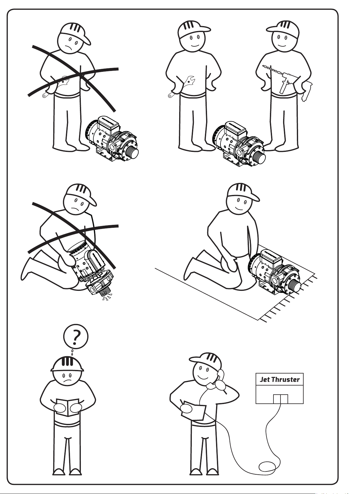
Installaon preparaon
- Determine pump posion, nozzle posion & hose roung throughout the ves-
sel
-Clean all stainless steel & composite parts thoroughly with acetone or Brake
cleaner. Make sure all grease is removed from parts.
-Use Polyurethane Marine sealant (for example Sikaex 291i) for all connecons
Check the shelf life!
-Prevent damaging of stainless steel parts by ferro items (Tools)

Nozzle’s position needs
to be 90° to Center line of
boat.
Nozzle’s position 7-10 cm
below waterline & Parallel to
waterline
Batteries directly next to pump
Most Crical steps to meet!
See all other steps and meet them as well
Pump must be below waterline

1: Pump always under the waterline
- Prevent contact with bilge water
- Install pump- zinc- anode
- Keep space behind pump unit (Venlator cap)
- Ensure space besides the pump for baeries
2: Baeries directly next to pump
- Use Opma Yellowtop baeries
- Install baeries on waterproof plywood and install baeries and secure safely
- When necessary: install series-parallel switch on top the baeries
- Keep cable length to absolute minimum. Take notes of cable length for evaluaon
- Connect negave of baery 1 with negave of service baery. (Common ground)
- Use proper baery pole clamps
- Use proper and good-ng terminals
- Install baery pole caps
3: Nozzle posion
- Nozzles as far forward (or in the stern) of the vessel
- Topside Nozzle tube 7-10cm under the waterline
- Installaon of Nozzle horizontal
- Nozzle 90 degrees to be installed to center-line of the vessel
- Nozzle can be located slightly forward and a of each other (staggered)
- Use 45-degrees elbow only in case of a small bow secon
- For a wide bow: do not use 45-degree elbows but curve the hose instead
- Install and connect the zinc anode with the stainless steel parts
4: Clean all threaded parts before using PU sealant

7 CM
15-20 cm
90�
90�
7 cm
125˚C
85
85
23
70
85
85
23
70
Jet Thruster controller
Controls Pump unit Valve bow Valve Stern 12V
+ -
Jet Thruster controller
Controls Pump unit Valve bow Valve Stern 12V
+ -
+ -
+ -
>25˚C
Hose max 60˚C
7 CM
15-20 cm
90�
90�
7 cm
125˚C
85
85
23
70
85
85
23
70
Jet Thruster controller
Controls Pump unit Valve bow Valve Stern 12V
+ -
Jet Thruster controller
Controls Pump unit Valve bow Valve Stern 12V
+ -
+ -
+ -
>25˚C
Slang max 60˚C
7 CM
15-20 cm
90�
90�
7 cm
125˚C
85
85
23
70
85
85
23
70
Jet Thruster controller
Controls Pump unit Valve bow Valve Stern 12V
+ -
Jet Thruster controller
Controls Pump unit Valve bow Valve Stern 12V
+ -
+ -
+ -
>25˚C
Hose max 60˚C
Step 1
Step 2
Step 3

- Clean all threaded parts with brake cleaner, dry it o with a clean paper towel
- Apply a good amount of PU sealant on both threaded parts before connecng them
- make sure the complete surface of thread is covered in PU sealant
- Remove any le over PU Sealant with the special wet wipes in the round can
- Aenon, the wet wipes are for removing aerwards the le over sealant. Do not clean upfront the
threaded parts with the wet wipes. This will cause the sealant not to bond and will cause leakage!!!
5: Water inlet and acces to shut o valve
- Ball valve must be easily accessible
- Inlet hose max 1 meter long, shorter always possible
- Installaon of water inlet may be possible from the side of the vessel
- Water inlet below waterline. Posion higher than pump is allowed
- Remove anfouling under ange
- Use supplied Stainless steel tool to twist water inlet into 90-degrees turn
6: Hose clamps and connecon:
- Use grease on the bolts
- Prevenon against corrosion (Vaseline spray)
7: Hose roung

7 CM
15-20 cm
90�
90�
7 cm
125˚C
85
85
23
70
85
85
23
70
Jet Thruster controller
Controls Pump unit Valve bow Valve Stern 12V
+ -
Jet Thruster controller
Controls Pump unit Valve bow Valve Stern 12V
+ -
+ -
+ -
>25˚C
Hose max 60˚C
7 CM
15-20 cm
90�
90�
7 cm
125˚C
85
85
23
70
85
85
23
70
Jet Thruster controller
Controls Pump unit Valve bow Valve Stern 12V
+ -
Jet Thruster controller
Controls Pump unit Valve bow Valve Stern 12V
+ -
+ -
+ -
>25˚C
Hose max 60˚C
Step 4
Step 5
Step 6
7 CM
15-20 cm
90�
90�
7 cm
125˚C
85
85
23
70
85
85
23
70
Jet Thruster controller
Controls Pump unit Valve bow Valve Stern 12V
+ -
Jet Thruster controller
Controls Pump unit Valve bow Valve Stern 12V
+ -
+ -
+ -
>25˚C
Slang max 60˚C

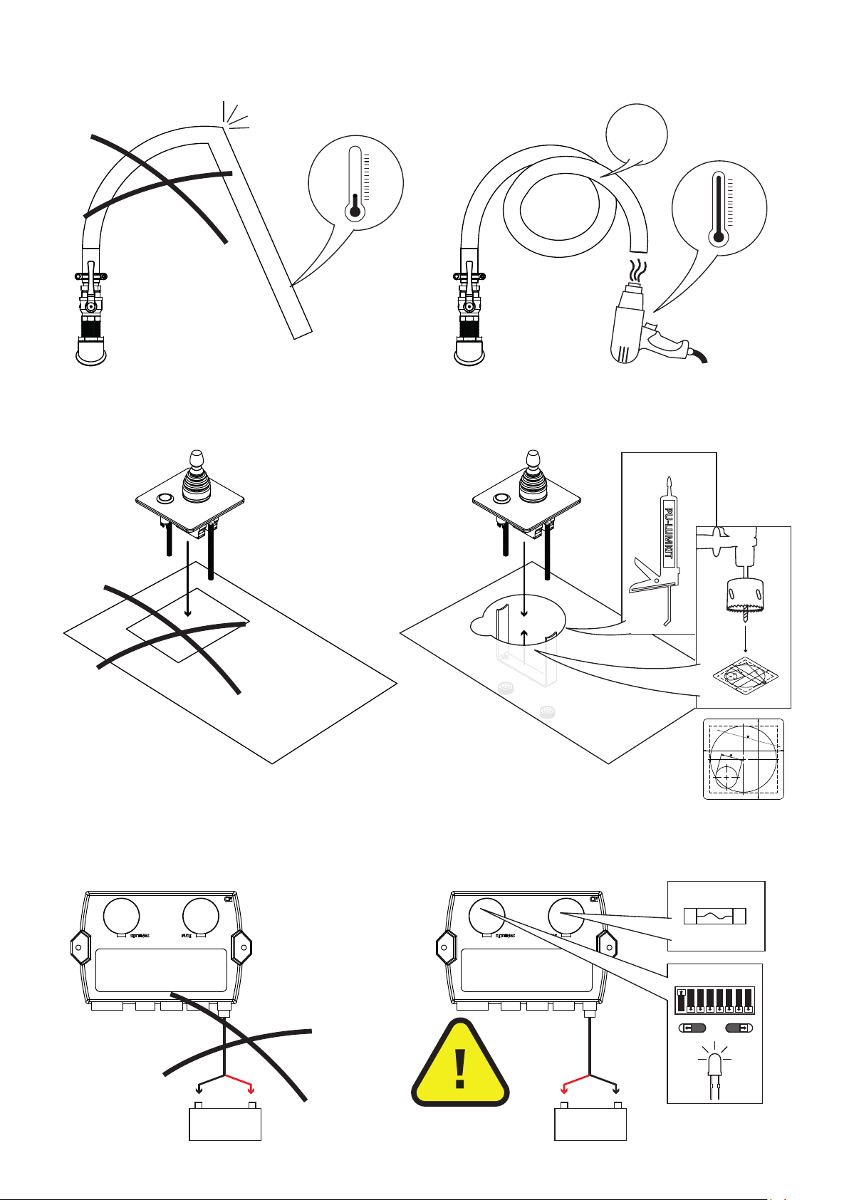
- Hoses may be above waterline
- Heat up hose with a electrical heat gun to be able to make a nice steady curve
- Cut hose to appropriate length with a sharp knife (do not saw). Cut coiled wire with pliers
- Prevent kinks of dents in hose
- Prevent damaging the hose (sharp parts in vessel)
- Aach hose to hull with bonding fasteners
8: Control panel in helm staon
- Use drilling template for installing control panel
- Glue front plate panel onto dashboard with exible marine sealant
9: Controller
- Preferably install controller near the switch panel
- Use the length of the valve cable (10m) and pump cable (5m)
- Connect controller with 12V Service baery (via switch panel)
- DO NOT change polarity of connecon cable! (will cause serious damage!)
- Check if connecters click with audible click
- Check dip-switch sengs for Single or Combi funcon (see next page)
7 CM
15-20 cm
90�
90�
7 cm
125˚C
85
85
23
70
85
85
23
70
Jet Thruster controller
Controls Pump unit Valve bow Valve Stern 12V
+ -
Jet Thruster controller
Controls Pump unit Valve bow Valve Stern 12V
+ -
+ -
+ -
>25˚C
Slang max 60˚C
7 CM
15-20 cm
90�
90�
7 cm
125˚C
85
85
23
70
85
85
23
70
Jet Thruster controller
Controls Pump unit Valve bow Valve Stern 12V
+ -
Jet Thruster controller
Controls Pump unit Valve bow Valve Stern 12V
+ -
+ -
+ -
>25˚C
Slang max 60˚C
7 CM
15-20 cm
90�
90�
7 cm
125˚C
85
85
23
70
85
85
23
70
Jet Thruster controller
Controls Pump unit Valve bow Valve Stern 12V
+ -
Jet Thruster controller
Controls Pump unit Valve bow Valve Stern 12V
+ -
+ -
+ -
>25˚C
Slang max 60˚C
Step 7
Step 8
Step 9
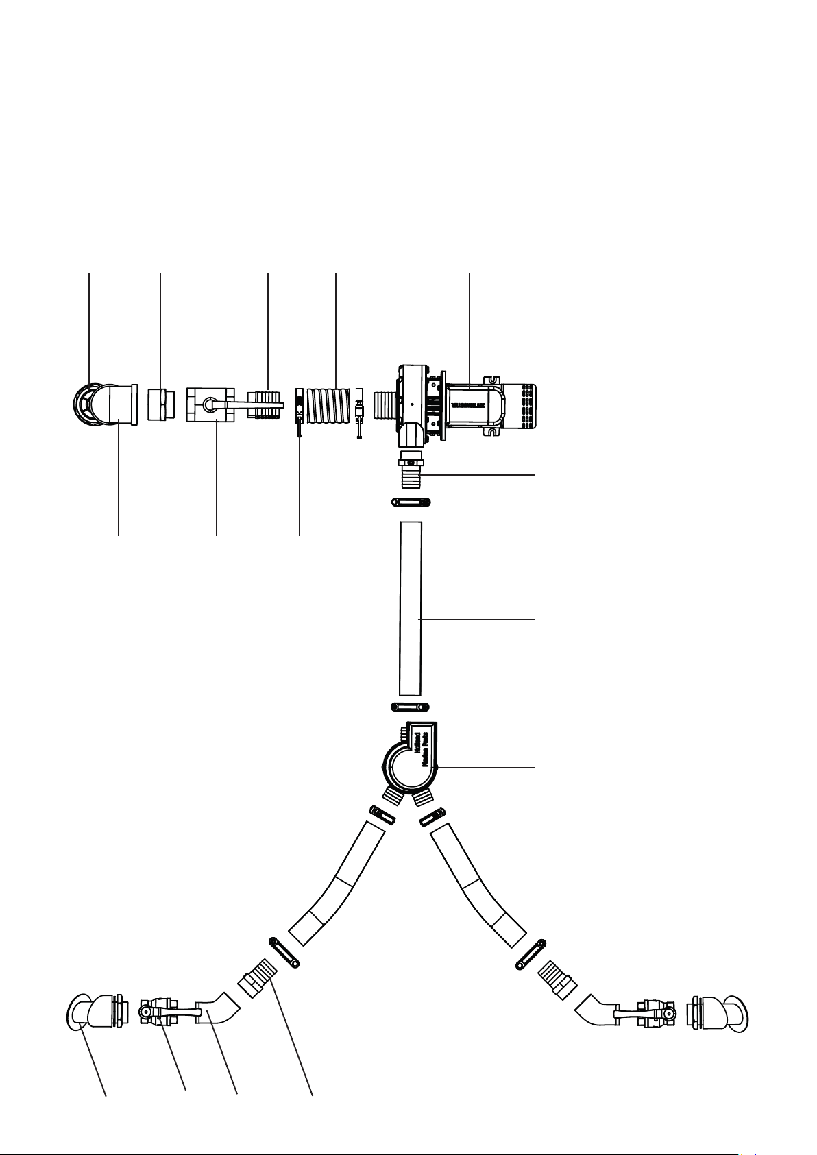
I-115-58I-330-00 I-316-00I-321-00
V-100-58
P-115-58
I-302-00
I-307-00
I-308-00
I-105-00
I-113-58
I-310-00
I-331-00
I-312-00
JT-30-50
JT-50-50
JT-50 example setup
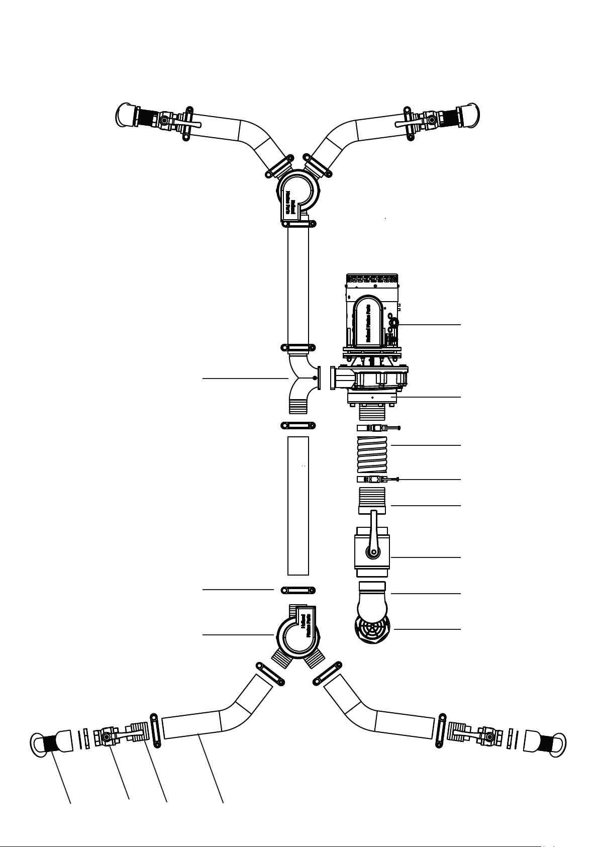
I-267-00
I-268-01
I-269-GF
I-271-00
I-213-00
CP-050-00
V-200-50
I-275-01
I-330-00 I-215-00I-321-00
I-270-01
I-331-00
P-259-00
JT-70-50
JT-90-50
JT-90 example setup

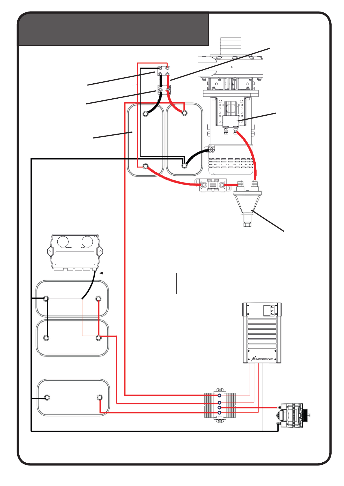
JT-30 12V
Charged 12V
Contactor
Main switch
Fuse
Opma baery
Controller
Service baeries
Start baery
Charger 12V
Alternator
Baery isolator
Do not extend this
power cable

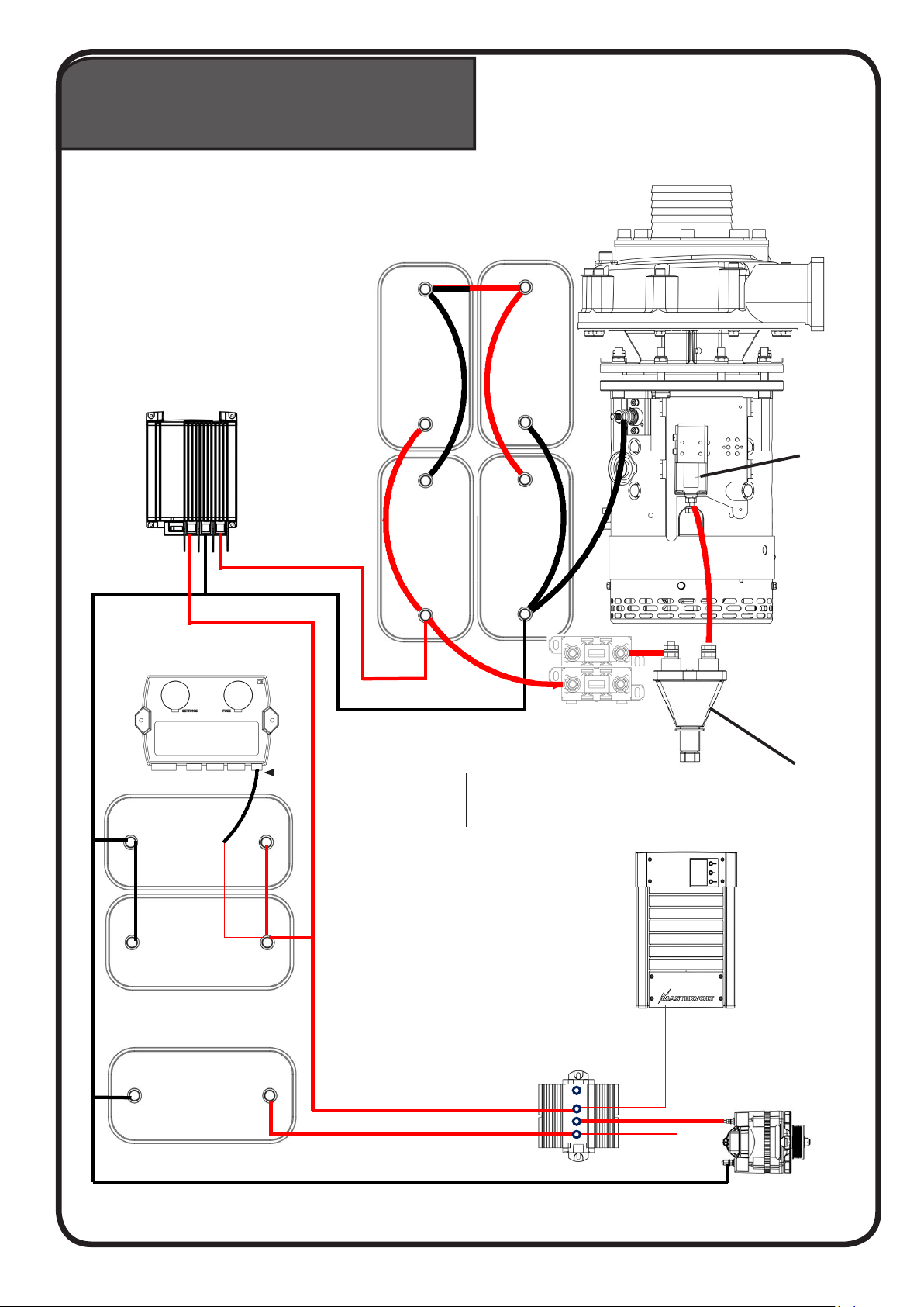
JT-50 24V
Charged 12V Step up charger
Contactor
Main switch
Fuse
Opma baeries
Controller
Service baeries
Start baery
Charger 12V
Alternator
Mac plus 12-24V
DC charger
Baery isolator
Do not extend this
power cable
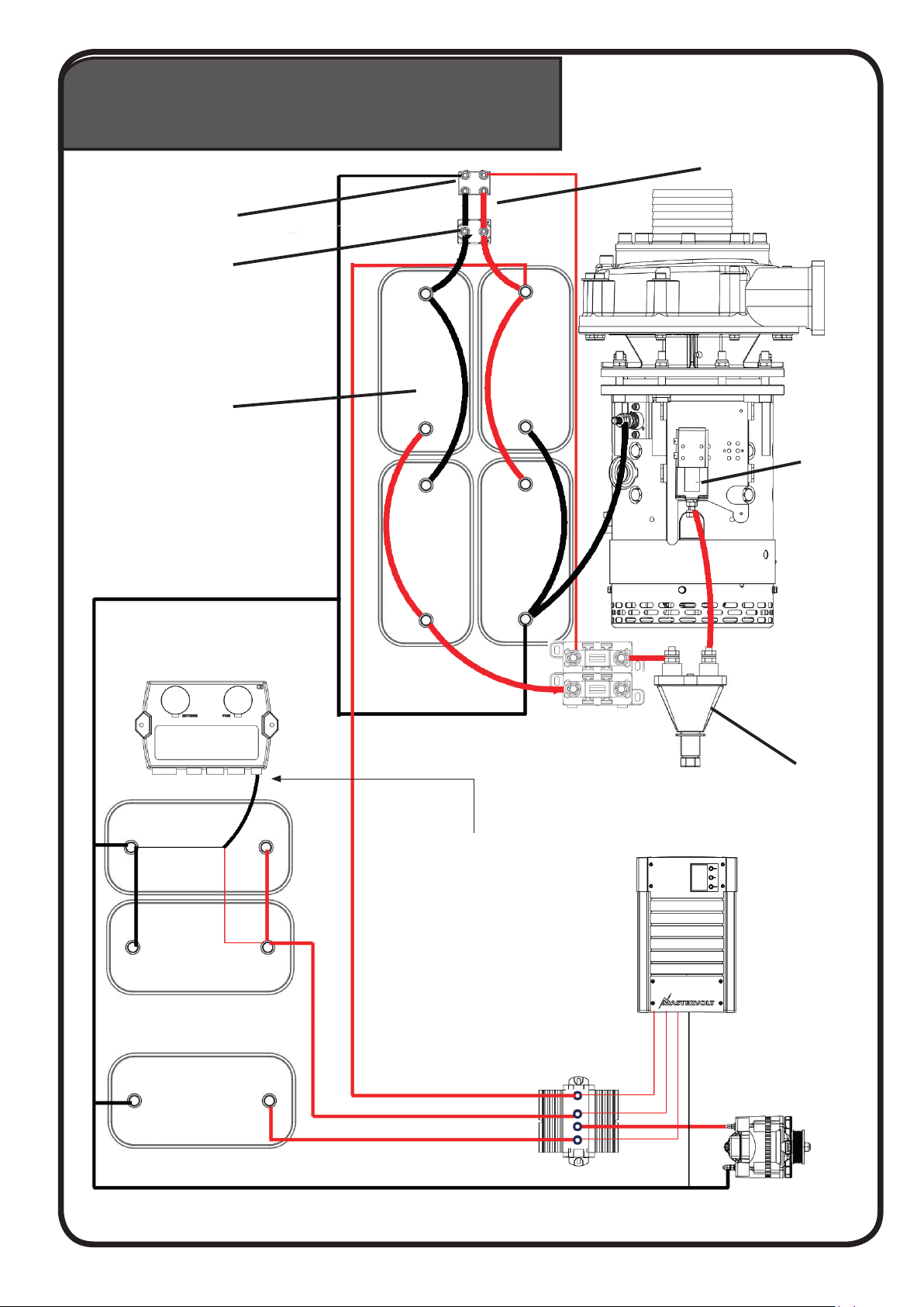
JT-50 24V
Charged with 12V + series parallel switch Strips factory mounted
Parallel switch
Boom side
Parallel switch
Top side
Contactor
Main switch
Fuse
Controller
Service baeries
Start baery
Baery isolator
Charger 12V
Alternator
Opma baeries
Do not extend this
power cable

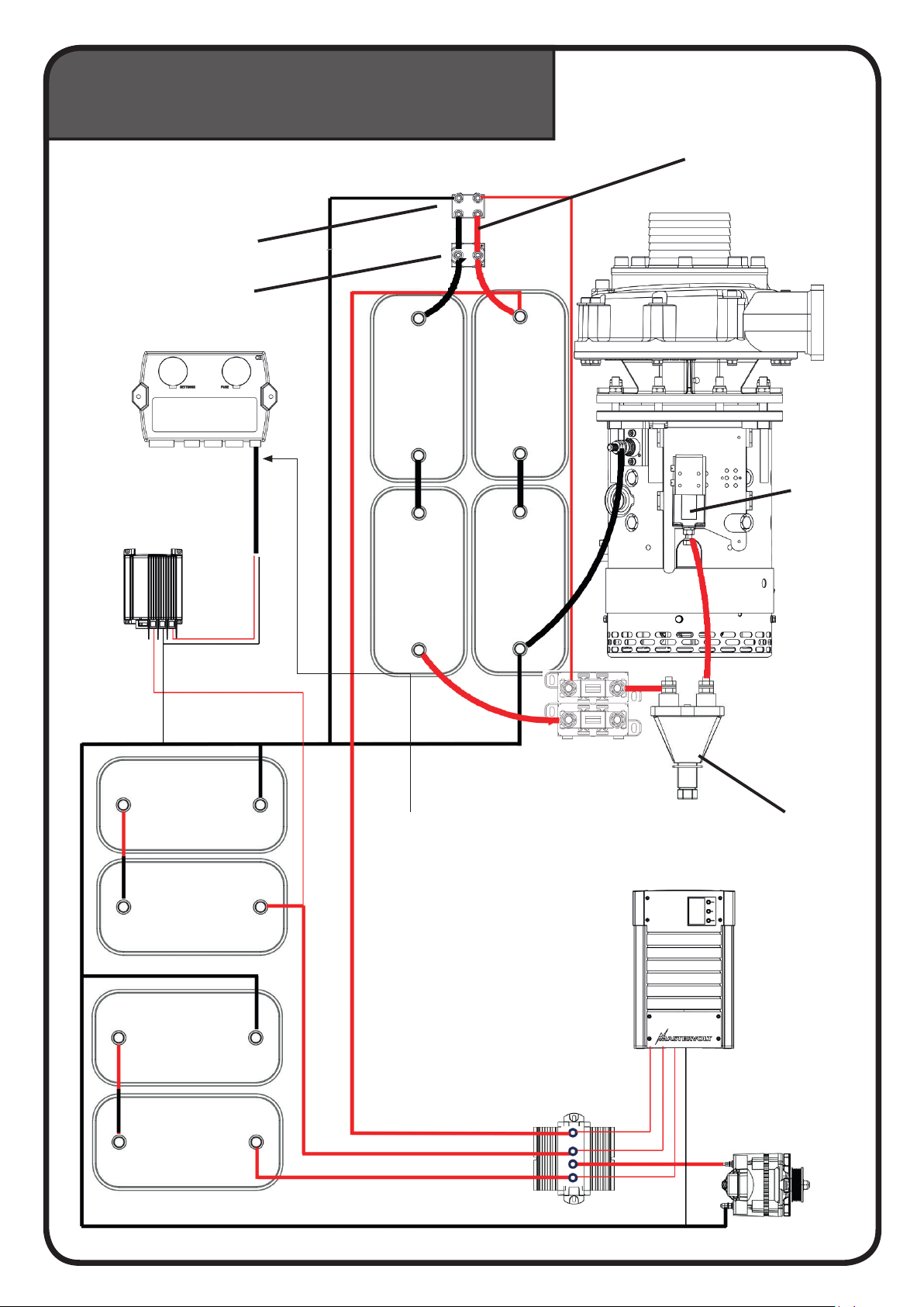
JT-90 24V
On a 24V board circuit
Main switch
Fuse
Contactor
2a
2b
1b
1a
Controller
Dc-Dc converter
24-12 20A
Service baeries
Start baery
Charger 24V
Alternator
Baery isolator
Do not extend this
power cable
JT-90 24V
Charged 12V Step up charger
Controller
Service baeries
Start baery
Charger 12V
Alternator
Mac plus 12-24V
DC charger
Contactor
Main switch
2a
2b
1b
1a
Fuse
Opma baeries
Baery isolator
Do not extend this
power cable
JT-90 24V
Charged with 12V + series parallel switch
Contactor
Main switch
Strips factory mounted
Controller
Service baeries
Start baery
Charger 12V
Alternator
Parallel switch
Boom side
Parallel switch
Top side
2a
2b
1b
1a
Fuse
Opma baeries
Baery isolator
Do not extend this
power cable
JT-90 48V
On a 24V board circuit
Strips factory mounted
Parallel switch
Boom side
Parallel switch
Top side
2a
2b
1b
1a
Controller
Service baeries
Start baery
Charger 24V
Alternator
Dc-Dc converter
24-12 20A
Fuse
Main switch
Contactor
Baery isolator
Do not extend this
power cable
Table of contents
Popular Boat manuals by other brands

 owner's manual")


Boston Whaler
Boston Whaler 180 Dauntless owner's manual

Hallberg-Rassy
Hallberg-Rassy MONSUN 31 instructions

Grady-White Boats
Grady-White Boats BIMINI 306 owner's manual

Sea Ray
Sea Ray 175 Sport owner's manual

Robalo
Robalo 2008 Walk Around Owner's and operator's manual

Malone
Malone MPG318 installation instructions


