COBIA 2016 277 CC User manual

Model Year 2016 page !1
Maverick Boat Company, Inc. • 3207 Industrial 29th St. • Fort Pierce,
Florida 34946 • (772)-465-0631 or (888)-shallow • Fax: (772) 489-2168
COBIA 277 CC
Owner’s Manual
WELCOME
Dear New Cobia Owner,
On behalf of Cobia Boats, I would like to congratulate
you on your purchase. We at Cobia strive to build the
best products possible and wish you years of trouble
free enjoyment. There are many things to know about
the operation, care and maintenance of our products
and the systems we install in them. Please review all
the applicable information for your new boat. The more
you know, the more you will enjoy your new Cobia.
Again, a heartfelt Thank You from myself and the
whole Cobia Family.
Scott Deal, President and CEO

Model Year 2016 page !2
Maverick Boat Company, Inc. • 3207 Industrial 29th St. • Fort Pierce,
Florida 34946 • (772)-465-0631 or (888)-shallow • Fax: (772) 489-2168
TABLE OF CONTENTS
Specifications...............................................................................2
Yamaha Engine Break-In Periods................................................3
Engine Stop Switch......................................................................3
Switch Panels & Helm……………….………………………………4
Yamaha Command Link Gauges..…………………………………4
277 Boat Layout …………………………………………………..…5
Cobia Duffel Bag..........................................................................6
Fuel/Water Separators.................................................................7
Garboard Drain Plug………………………….……………………..7
Bilge Access………………………………….………………………8
Bilge System................................................................................9
Ball Valves, Thru Hull Fittings, & Scuppers................................10
Head Systems.......................................................................11-13
Stainless Boarding Ladder.........................................................14
Props..........................................................................................14
Fuel System...............................................................................15
Steering......................................................................................16
Self Bailing Cockpit....................................................................17
Livewell System.........................................................................17
Rod Lockers...............................................................................18
Fish Lockers...............................................................................18
Anchor Locker / Rode Storage...................................................19
Table Lift……………………………………………………………..19
Trim Tabs…………………………………….………………………20
Macerator System……………………………….………………….21
Console/Head Access………………………….…………………..22
Saltwater Washdown………………………………………….……22
Freshwater System………………………………………………23
Battery Switch and Main Distribution Panel..……………..24-25
Battery Charger......................................................................26
Leaning Post and Tackle Station ...........................................27
Aft Seating..............................................................................28
Optional Bow Cushion Set......................................................28
Cockpit Bolsters......................................................................29
Pop-up Bow Light and Cleats…………….…………………….29
T-Top Options…………………………………………………….30
Optional Stereo System..........................................................31
Optional Windlass System................................................31-32
Wiring System Diagrams...................................................33-36
Warranty.................................................................................37
277 SPECIFICATIONS
L.O.A............................................................27’ 07”
BEAM.............................................................9’ 08”
DRAFT................................................................22”
WEIGHT W/O ENGINE.........................5,200 LBS.
FUEL CAPACITY......................................189 GAL.
DEADRISE @ TRANSOM..........................21 DEG
MAXIMUM H.P............................................500 HP
TRANSOM HEIGHT…….......................25” TWINS
Model Year 2016 page !3
Maverick Boat Company, Inc. • 3207 Industrial 29th St. • Fort Pierce,
Florida 34946 • (772)-465-0631 or (888)-shallow • Fax: (772) 489-2168
ENGINE
Engine stop switch (above)
Engine Break-In Period
New engines require a period of break-in to allow
the surfaces of the moving parts to mate evenly.
Different engines require different break-in periods
and methods. For instructions on break in methods,
refer to your Yamaha Engine Owner’s Manual for
the correct break-in procedures and times for your
model engines
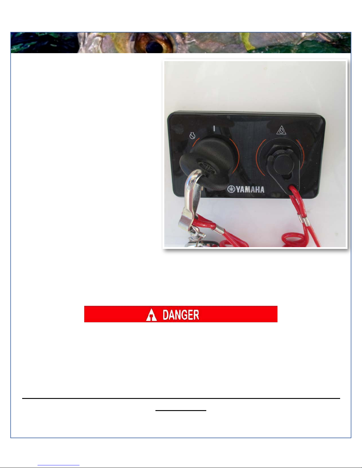
Engine Stop Switch
If activated, the spring loaded engine stop switch
will automatically shut down the engine during
emergency situations to prevent uncontrolled or
unattended operation. Certain emergency
conditions (e.g., turbulent water, wakes,
unanticipated movement) may impair a person’s
ability to operate the craft safely. The switch,
located on the helm, must have the safety lanyard
attached at its base. This activates the protective
shutdown circuitry.
Securely attach the other end of the lanyard to the
operator of the boat. If the operator moves, falls or
is at an unsafe distance from the steering wheel,
tension on the lanyard will pull it from the switch.
When the lanyard is removed, the engine stop
switch is released and automatic engine shutdown
occurs.
Engine Stop Switch
An engine stop switch system that is not used or does not function properly can cause death or serious injury.
DO NOT operate the boat if the engine stop switch system does not function properly. Go to a Cobia Dealer to
have this resolved immediately
The lanyard should be securely attached to the boat operator at all times that the
engine is on.
Model Year 2016 page !4
Maverick Boat Company, Inc. • 3207 Industrial 29th St. • Fort Pierce,
Florida 34946 • (772)-465-0631 or (888)-shallow • Fax: (772) 489-2168
SWITCH AND
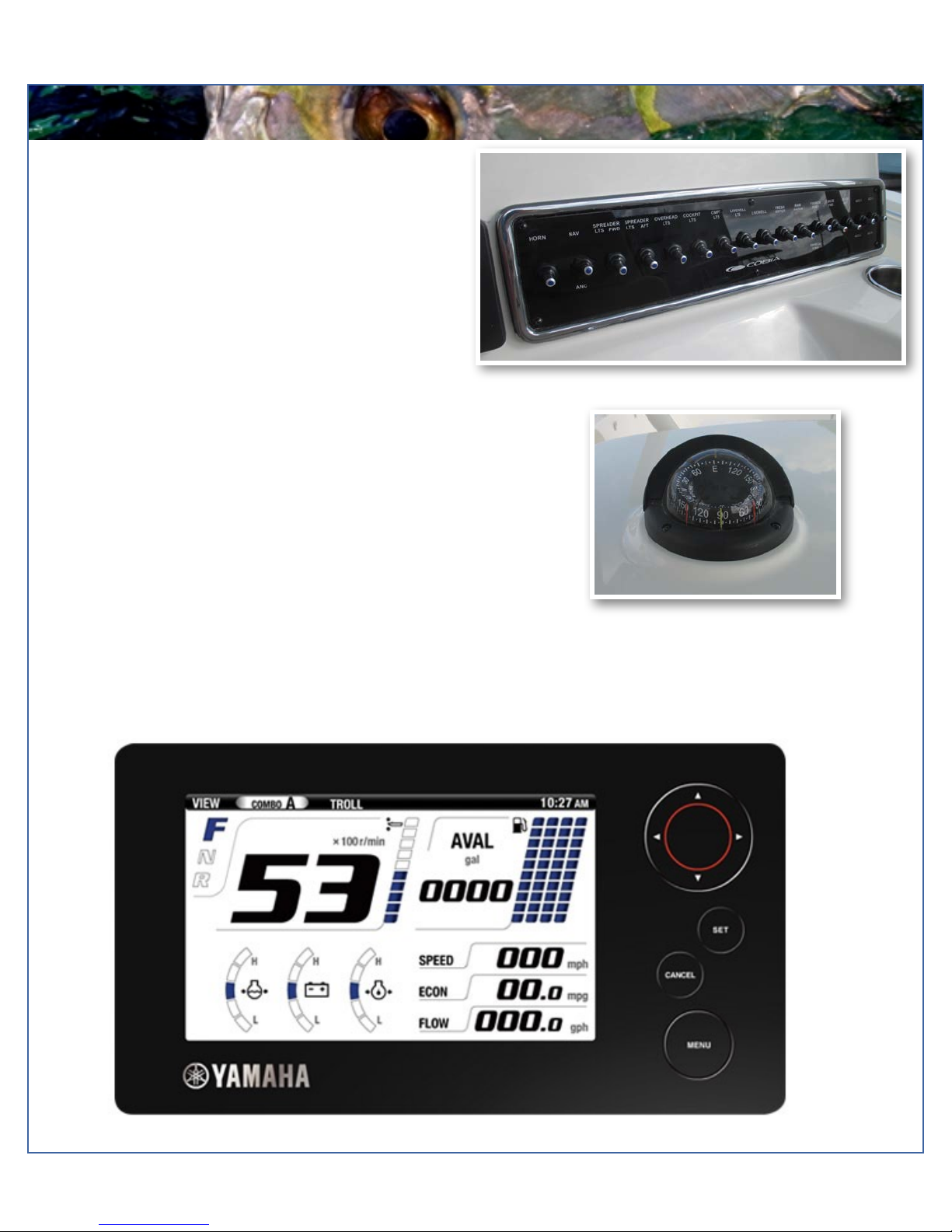
Switch Panel & Helm
At the helm of your Cobia, you have a main switch
panel, which is located above the steering wheel. This
panel controls your lights, horn, accessories, livewell,
and your bilge. When a switch is in the “on” position, its
tip is illuminated. This alerts you that the associated
accessory should be functioning and also reminds you
to turn it off during boat shutdown. When the “NAV” light
switch is in the “on” position, the labels for the switches
will be illuminated. To the right of the steering wheel you
have your two trim tab switches, (Refer to page 20 for
trim tab operation.) The boat also comes standard with
a compass mounted on top of the console.
Compass
Command Link Gauges
Yamaha’s new 6YC Command Link gauge comes standard on your new Cobia. This gauge allows access to more
information and is user-selectable so you can choose the functions displayed. Speed data can be displayed from a pitot tube,
Triducer, or NMEA protocol GPS unit. To learn the gauge’s full functionality refer to your Yamaha engine owner’s manual
located in the Cobia duffel bag.
Switch Panel

Model Year 2016 page !5
Maverick Boat Company, Inc. • 3207 Industrial 29th St. • Fort Pierce,
Florida 34946 • (772)-465-0631 or (888)-shallow • Fax: (772) 489-2168
BOAT LAYOUT
277 Deck Layout
Anchor Locker/Raw Water Washdown
Storage Hatches
Table Lift
Cooler Box
Forward Console/Head Entry
Fuel Fill
Leaning Post/Tackle Station
47 Gal. Fish Lockers
42 Gal. Livewell
Fresh Water Sprayhead
Boarding Ladder
Dry Storage

Model Year 2016 page !6
Maverick Boat Company, Inc. • 3207 Industrial 29th St. • Fort Pierce,
Florida 34946 • (772)-465-0631 or (888)-shallow • Fax: (772) 489-2168
COBIA DUFFEL BAG
Cobia Duffel Bag
Cobia Duffel Bag
Along with your boat, you received a Duffel Bag with your new Cobia. Inside the
Duffel Bag are the following items:
•Large Livewell Standpipe
•Short Livewell Standpipe
•1.5” Livewell Pacifier Plug
•2 ignition Keys and Emergency Kill Cord /Engine Stop Lanyard
•Yamaha Engine Owner’s Manuals
•Engine Start Cord
•Various Accessories Manuals

Model Year 2016 page !7
Maverick Boat Company, Inc. • 3207 Industrial 29th St. • Fort Pierce,
Florida 34946 • (772)-465-0631 or (888)-shallow • Fax: (772) 489-2168
Fuel-Water Separator
The Yamaha Fuel - Water Separators are installed behind the rear
access panel on the starboard transom side along with the fuel
system primer bulbs. The new, improved 10-micron filter provides
superior filtration ahead of the engine's onboard filters and
injectors. Large filtering and water capture areas maximize
filtration while maintaining adequate flow rate for larger engines.
The fuel separator can be checked by removing it from the
mounting bracket and dumping it into an approved waste
collection device. If there appears to be an excessive amount of
water, the filter component should be replaced. See your
authorized Cobia Dealer for replacement parts.
Maintenance Note
Yamaha recommends replacing the 10- micron fuel filter on new boats after the first 10 hours or 1 month of
operation and every 50 hours or every 6 months thereafter. In areas of high humidity where water in fuel supplies is a
problem or extensive engine operation occurs, more frequent replacement may be necessary.
Garboard Drain Plug
The garboard drain plug is the small metal plug located at
the lowest point on the hull, at the bottom of the transom
right above the keel. The drain has been designed so that
it can be loosened by hand while the hull is out of the
water for draining. This allows the plug to stay in contact
with the surrounding frame so you’ll never misplace or
lose it. You can completely remove the insert by pulling
back and continue turning in a counter clockwise motion.
It is manufactured with a rubber seal in place to ensure
the bilge is watertight. Always make sure before putting
the boat in the water that this plug is hand tightened
firmly. Excess water in the bilge may be an indication of a
problem with this plug or the automatic bilge pump. Refer
to page 8 of this Owner’s Manual for information on your
boats bilge system.
FUEL-WATER SEPARATOR & DRAIN
Model Year 2016 page !8
Maverick Boat Company, Inc. • 3207 Industrial 29th St. • Fort Pierce,
Florida 34946 • (772)-465-0631 or (888)-shallow • Fax: (772) 489-2168
BILGE ACCESS
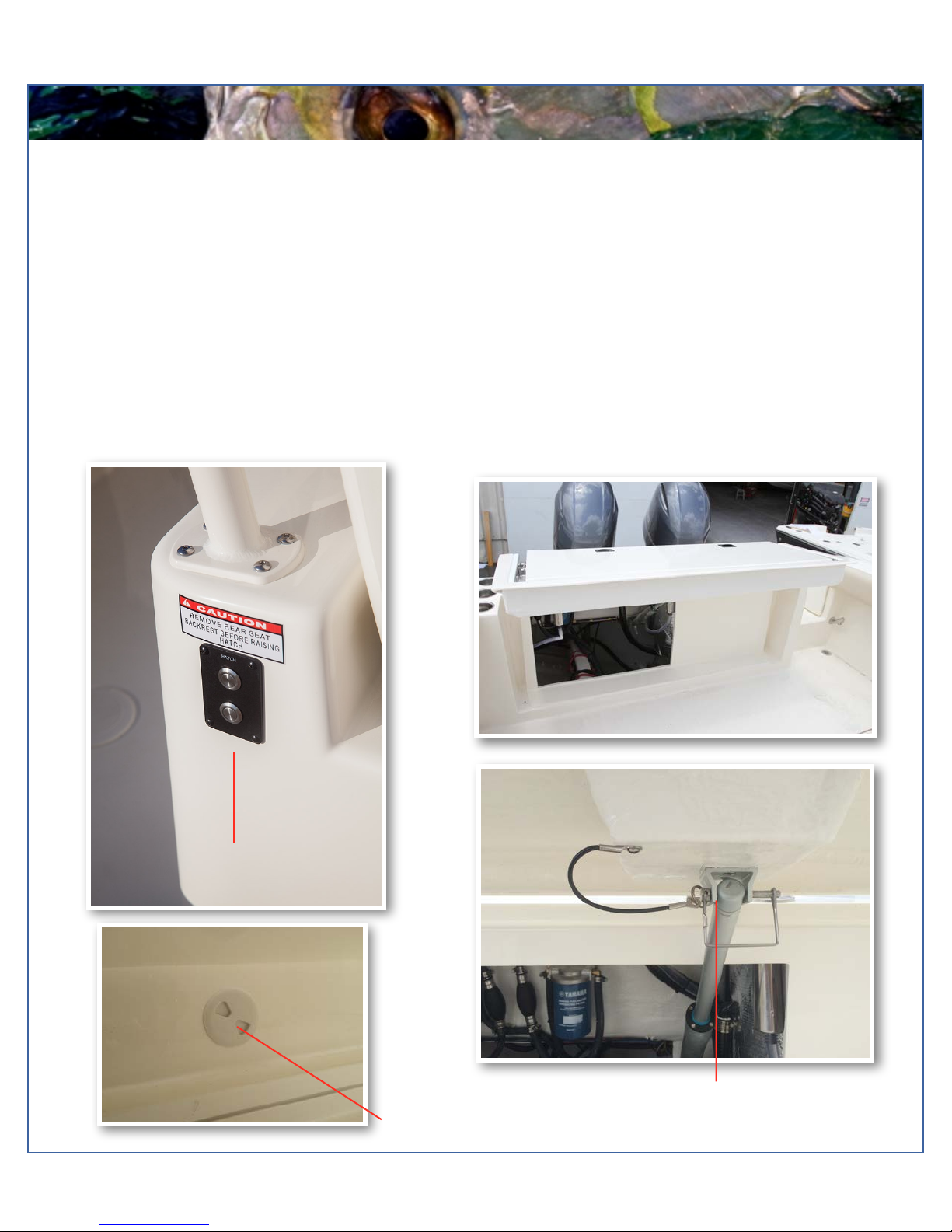
Bilge Access
Hatch Control
Accessing the bilge in the 277 is made easy. First, locate the controls for the electronic lift assist, labeled “Hatch”, mounted on
the starboard side of the tackle station directly across from the gunnel. Next, press and hold the top button on the controls. This
will cause the rear access to lift revealing the bilge access. To lower the hatch simply press and hold the bottom button on the
control panel until aft section is fully closed. Remember the electronic lift assist operates using the house battery system. Note
that the aft seat backrest must be removed to fully open the hatch. Failure to remove the backrest may result in damage
to the backrest and or the hatch lifting mechanism. In the event that the boat does not have power to electronically lift the
hatch, the electronic lift can be disengaged by lowering the bench seat and using the access opening shown below to remove
the pin from the electric ram. Keep in mind that at his point the hatch will no longer be supported in the up position and will
require being held up to maintain access to the bilge. Once the work in the bilge is finished and power is restored to the hatch
lift it is important to attach the ram to the hatch with the pin once again to secure the door in the closed position. See page 11
for access to the forward bilge.
Electric Ram and Hatch Pin
Electric Ram Override Acces
Model Year 2016 page !9
Maverick Boat Company, Inc. • 3207 Industrial 29th St. • Fort Pierce,
Florida 34946 • (772)-465-0631 or (888)-shallow • Fax: (772) 489-2168
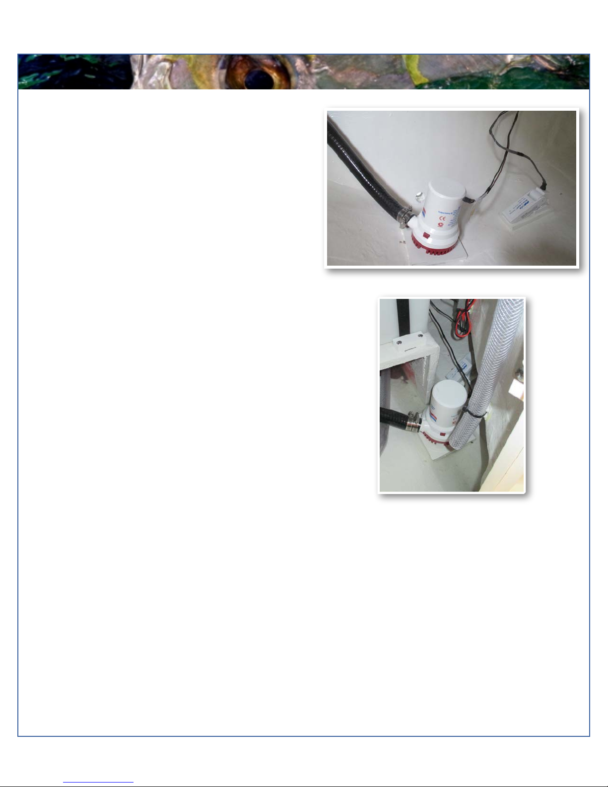
Fwd. Bilge Pump and Float Switch
BILGE
Bilge
The bilge of your Cobia should always be checked before and
after a launch. While checking the bilge, note that a small
amount of water in the bilge is normal. However, a large
amount of water or any signs of fuel or oil requires immediate
attention. If such a situation exists, the boat should be
taken to a certified marine technician immediately. Never
pump fuel or oil overboard while your boat is in the
water.
Large quantities of water in the bilge may be an indication of
a leak or that the bilge pump and/or automatic float switch is
not functioning properly due to a jam, clog or electrical issue.
The automatic float switch is wired to the hot side of the
battery switch through the “BILGE” fuse at the battery switch
panel. When functioning properly, the float switch activates
the bilge pump to pump water overboard once water in the
bilge reaches a level that submerges the switch.
If your bilge pump does not come on when the float switch is
submerged, attempt to manually engage the bilge pump on
your switch panel. If the bilge pump comes on and evacuates
the water, it is likely that the float switch is not functioning
properly. If the bilge pump does not come on via the switch
panel, check the corresponding breaker on the main
distribution panel (page 24) to see if a breaker has been
tripped. If the breaker has been tripped, reset it, and turn the
switch on again, listening for the bilge pump to turn on.
If the bilge pump fails to turn on, turn the battery switch to the OFF position, then unhook the bilge pump from its cradle
by pressing the locking tab and twist motor housing counter-clockwise. You will feel the pump release from the cradle.
The entire bilge pump and wiring should release from the cradle. After removing the pump, check the underside and
impeller areas for miscellaneous items that might clog the pump. If any obstructions are present remove the debris and
set the pump back into the cradle. Once set back in the cradle, press the pump down on the base then twist until the lock
button snaps it into place. Once this is completed you can try to turn the pump on again.
If the bilge pump still does not turn on, it likely needs to be replaced. It is not recommended to use your boat if the bilge
pump and/or float switch are not functioning properly.
Aft Bilge Pump and Float Switch
Model Year 2016 page !10
Maverick Boat Company, Inc. • 3207 Industrial 29th St. • Fort Pierce,
Florida 34946 • (772)-465-0631 or (888)-shallow • Fax: (772) 489-2168
SYSTEMS
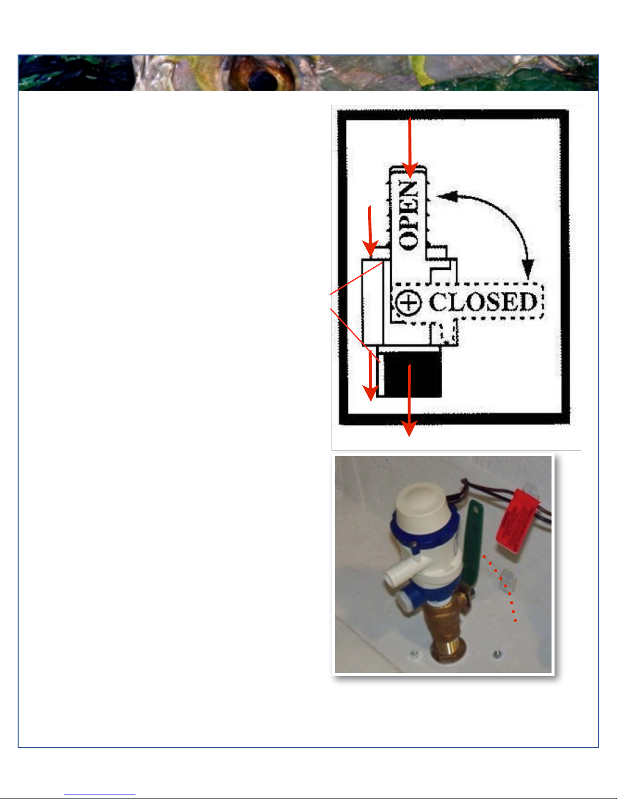
THE LIVEWELL PUMP
ASSEMBLY IN THE “OPEN”
POSITION
Ball Valves
Ball valves can be used to serve several purposes. They
allow seawater to enter the boat, in the case of livewells,
and they also act as a safeguard to stop water from
entering. To tell which position a ball valve is in, open or
closed, look at the valve and determine the direction of
flow. When the ball valve handle is in the same position
as the direction of flow, the valve is in the “OPEN”
position. When the ball valve handle appears to cross the
direction of flow, the valve is in the “CLOSED” position.
The ball valves can be accessed in the bilge compartment
behind the aft seating.
277 Deckdrain System
The deckdrain system is equipped with 1-1/2” thru hull
fittings through the aft port and starboard hull sides.
These fittings have to be installed lower than the drains in
the cockpit floor so that gravity will allow the cockpit to
drain free of water. This puts these fittings very close to
the water line of the hull. These drains are rigged with ball
valves that can be opened and closed to control the flow
of water. In the open position, these ball valves will allow
water to flow freely from the cockpit, thus making the boat
“self-bailing”. When closed, no water will be allowed to
travel to or from the cockpit.
277 Livewell Pump Assembly
The livewell pump assembly is composed of a scoop
strainer mounted to the bottom of the hull, a thru hull
fitting, ball valve assembly, and the pump. As you can
see, the ball valve assembly is in the “OPEN” position.
This is the correct position for the operation of the livewell
system.
Water Flow
CLOSED
Model Year 2016 page !11
Maverick Boat Company, Inc. • 3207 Industrial 29th St. • Fort Pierce,
Florida 34946 • (772)-465-0631 or (888)-shallow • Fax: (772) 489-2168
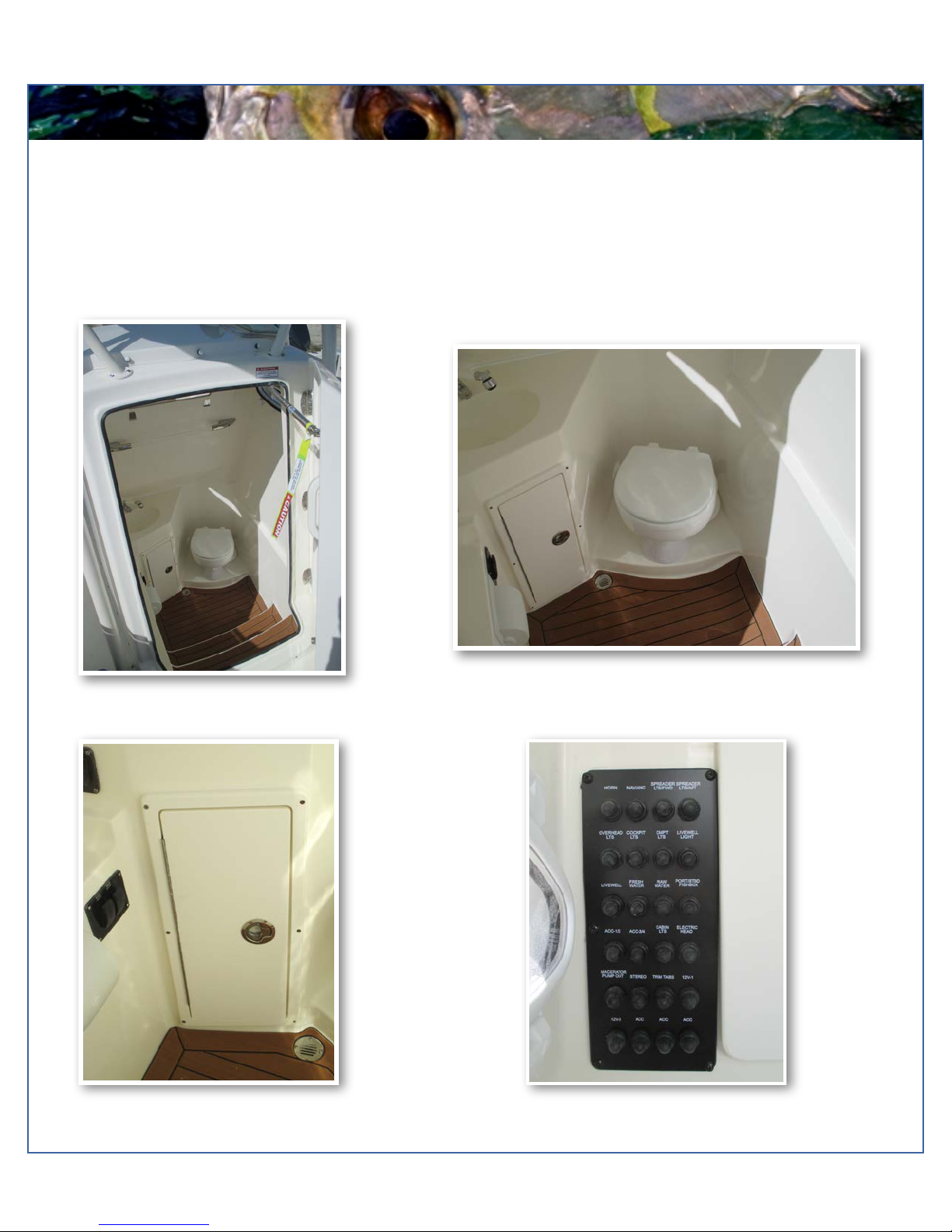
HEAD OPERATION
Head Unit
Inside the console is the head unit. There are steps that lead into the head unit which houses an electric head, fresh water
sink with spray nozzle for rinsing off, switch panel for flushing head and on-off switch for the macerator, and a lighted towel-
rack bar. The main DC breaker panel (for switch panel accessories) is inside along with two port hole windows. There is
also access to the macerator, y-valve, water intake and discharge for the toilet and holding tank, and another access to the
forward bilge. Lift the forward console seat cushion for access to a built in 62 qt cooler.
Access to Forward Bilge Area
Head Console Access
Electric Head Option
Main Breaker Panel
Model Year 2016 page !12
Maverick Boat Company, Inc. • 3207 Industrial 29th St. • Fort Pierce,
Florida 34946 • (772)-465-0631 or (888)-shallow • Fax: (772) 489-2168
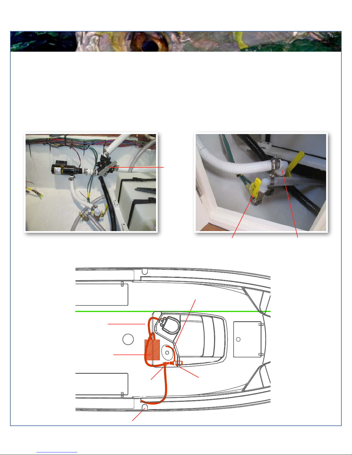
ELECTRIC HEAD
Electric Head
The macerator is to be used only with direct discharge thru hull. Macerator will not be used for dockside pump out of the
holding tank. To flush the head, make sure intake valve is in the open position. The intake valve is located under the lower
step. It is the valve on the left. This supplies your head with the water it will need to operate correctly. Then press the toilet
switch and the waste is pushed into the holding tank. The macerator has nothing to do with the flushing of the toilet. The
macerator is only used for overboard discharge while outside the legal dumping limits. To discharge outside legal limits, open
the thru hull discharge valve located directly across from the intake valve, turn the Y-Valve to the direction of the macerator,
and flip macerator switch to the “ON” position. The Y-Valve is located under the top step in the head unit.
aTHis is
aTHis is
aTHis is
aTHis is
aTHis is
6 Gal. Holding Tank
Y-Valve
Waste Pumpout Fitting
To Tank
Overboard Discharge
Discharge Valve
Intake Valve
Y-Valve
Head System Diagram
Macerator Pump

Model Year 2016 page !13
Maverick Boat Company, Inc. • 3207 Industrial 29th St. • Fort Pierce,
Florida 34946 • (772)-465-0631 or (888)-shallow • Fax: (772) 489-2168
ELECTRIC HEAD (CONT.)
Electric Head Continued
The Jabsco Y-Valve is designed to provide flexibility of onboard
waste management by diverting waste either to the dockside
pump-out fitting or directly overboard where legal to do so. Check
local and Federal regulations to determine where direct overboard
discharge of untreated waste is permitted.
Some near shore areas and inland areas are designated as "No-
Discharge Zones" where the discharge of any onboard waste, even
treated waste is strictly prohibited. Many of these areas require a
waste retention system that can be positively secured in an
onboard retention mode.
The Jabsco Y-Valve accommodates this requirement by providing
the ability to add a padlock that secures the selector handle in
either direction to ensure waste is directed to an onboard holding
tank. The Y-Valve may also be used to direct waste from a holding
tank to a waste deck plate for removal by a dockside pump-out
facility.
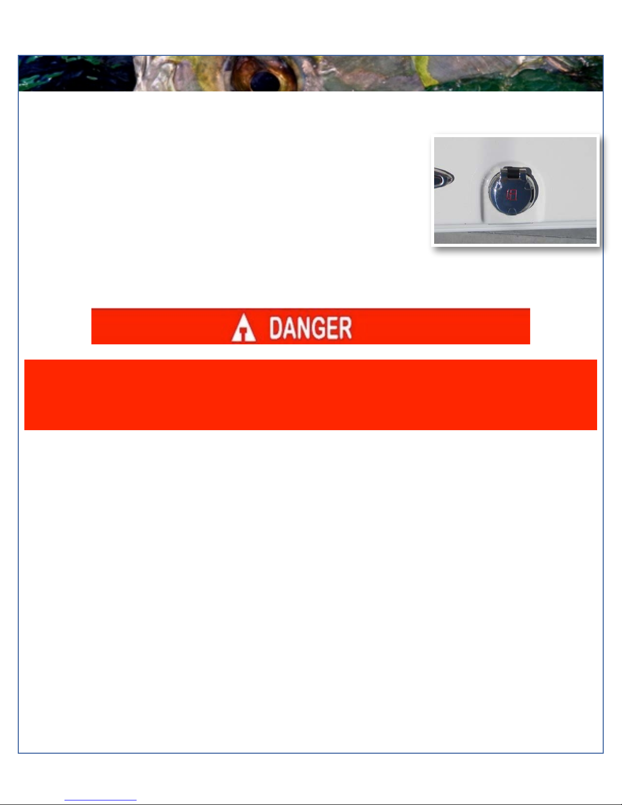
Toilet & Macerator Switch Located on the
Starboard Aft Wall of the Head Console
Macerator Used for Pumping Direct
Overboard Discharge
Y-Valve Used to Direct Waste Discharge

Model Year 2016 page !14
Maverick Boat Company, Inc. • 3207 Industrial 29th St. • Fort Pierce,
Florida 34946 • (772)-465-0631 or (888)-shallow • Fax: (772) 489-2168
LADDER AND PROPS
Props
Prop selection on your Cobia is determined by your local
Cobia Dealer, but all props are based on recommendations
from Cobia Boat Company and Yamaha Marine in order to
give your boat maximum overall performance. The needs
of your prop will determine the prop design and size that
best fits your performance requirements.
Always inspect the engine and prop prior to launching your
boat with the engine off. Key prop issues include tangled
fishing line or other types of debris, cracked blades or fluid
leaking out of the seal. Look for fishing line tangled around
the prop or lower unit seal. Consult your Yamaha’s
Owner’s Manual to address these issues.
No passenger should attempt to enter or exit the boat by the ladder or by any other means while
the engine is on.
Stainless Boarding Ladder
This Cobia model comes standard with a telescoping stainless steel
boarding ladder integrated into the port aft platform area. This provides
a stepping area while the ladder is in the up position as shown below.
Once the ladder is down and in the extended position, close the lid
cover for safe and secure entry and exit via the ladder.
Model Year 2016 page !15
Maverick Boat Company, Inc. • 3207 Industrial 29th St. • Fort Pierce,
Florida 34946 • (772)-465-0631 or (888)-shallow • Fax: (772) 489-2168
FUEL SYSTEM
FUEL SYSTEM
The Cobia 277 CC comes equipped with a 189 gallon fuel cell stationed below the
leaning post between the stringer system. Every fuel tank is pressure tested at the
factory before and after installation. Should you experience any fuel related
problems or suspect problems with the fuel system, immediately take your boat to a
Cobia Dealer. The primer bulbs are located next to the fuel-water separators in the
bilge access hatch. (see page 7)
The fuel sending unit and fuel pick up on the tank can be accessed at the pie hole on
the cockpit floor behind the leaning post. The fuel vent and the fuel fill at the tank can
be accessed at the pie hole forward of the leaning post.
CAUTION—Do not smoke while filling the tank. Be sure to turn off the engines and all electrical
equipment when fueling the boat to prevent accidental discharges of static electricity. Use only the
recommended gasoline (see Yamaha’s Owner’s Manual). Do not use fuels with alcohol or related
derivatives that can cause marine fuel system hoses to deteriorate. Be sure to inspect all fuel
connections annually for signs of leaks or loose fittings.
aTHis is
aTHis is
Model Year 2016 page !16
Maverick Boat Company, Inc. • 3207 Industrial 29th St. • Fort Pierce,
Florida 34946 • (772)-465-0631 or (888)-shallow • Fax: (772) 489-2168
OPTIONAL STEERING
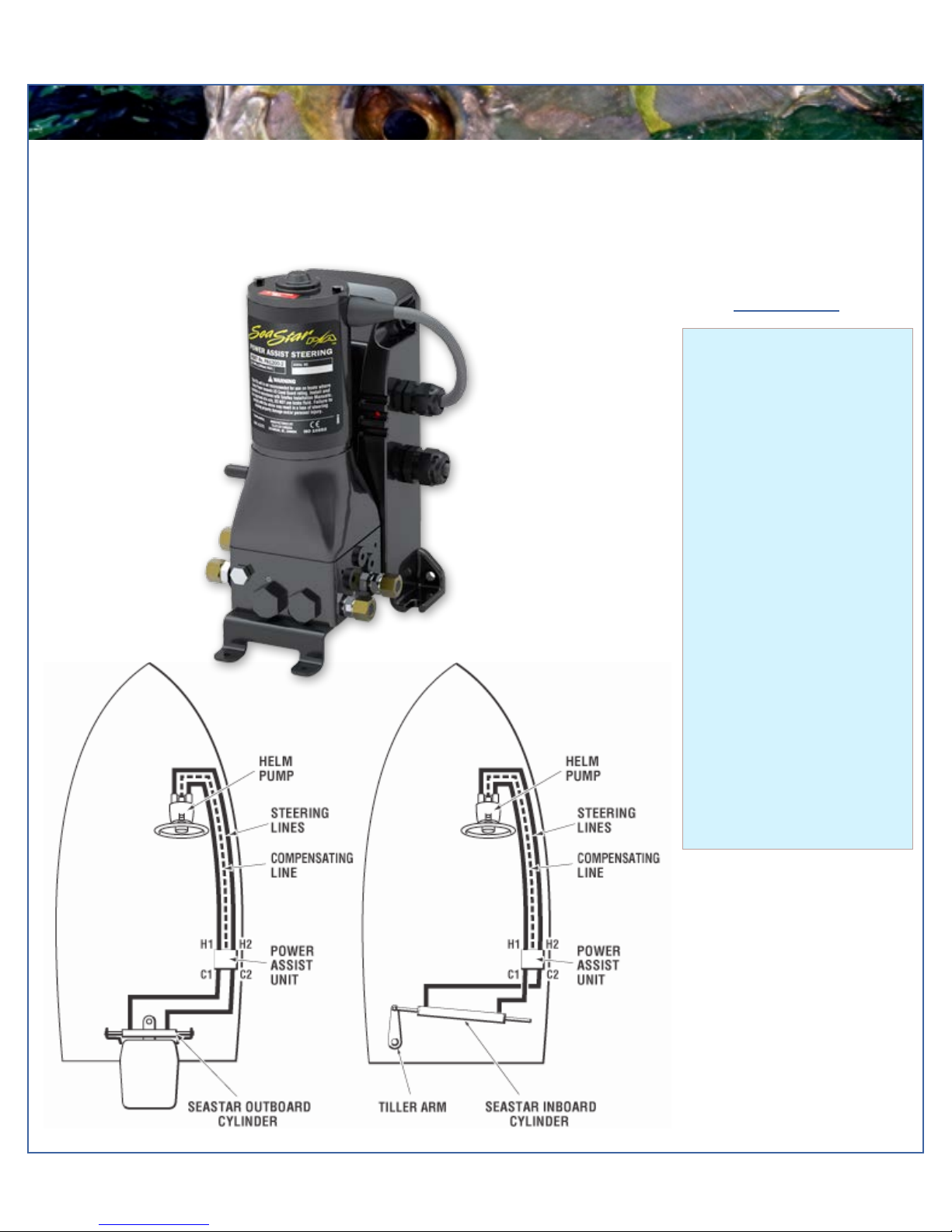
Power Assist Steering
The Power Assist pump for the steering is mounted on the forward bulkhead in the aft bilge area. This pump greatly reduces
the amount of pressure you have at the wheel and will make your boating a much more pleasurable experience.
At A Glance
•Dramatically reduces wheel
torque
•Easy to install
•Simple “add-on” to existing
Sea Star manual system
•Compatible with SeaStar
Power Purge system
•Number of turns to lock
remains the same
•Ignition protected
•Auto recognize system
voltage (12V or 24V)
•ABYC, CE, NMMA, ISO
10592 Approved
•Return to manual in failure
mode
•Capable of floor or wall
mount. No need to purchase
extra kits
Model Year 2016 page !17
Maverick Boat Company, Inc. • 3207 Industrial 29th St. • Fort Pierce,
Florida 34946 • (772)-465-0631 or (888)-shallow • Fax: (772) 489-2168
SELF-BAILING COCKPIT & LIVEWELL
Self Bailing Cockpit
The cockpit is designed to be self-bailing, meaning that all
the water that comes into the cockpit will be directly
drained overboard. This keeps the boat from acquiring
standing water and allows the boat to drain at all times,
including while the boat is docked.
Water drains out of the cockpit through two aft cockpit
drains located at the far aft cockpit floor on both the port
and starboard sides. Each side drains overboard through
the side of the hull independently. None of this water is
drained into the bilge. Refer to page 10 for operation of
the ball valve associated with this system. The ball valves
are located behind the aft seating.
The bilge is designed to drain any water entering the
inside of the hull. All hoses are sealed and double
clamped during construction. Continuous or periodic
running of the automatic bilge pump may be an indication
of a hose leak or break in a seal, and should be
investigated by a Cobia Dealer immediately. Refer to page
8 for further information regarding bilge pump operation
and maintenance.
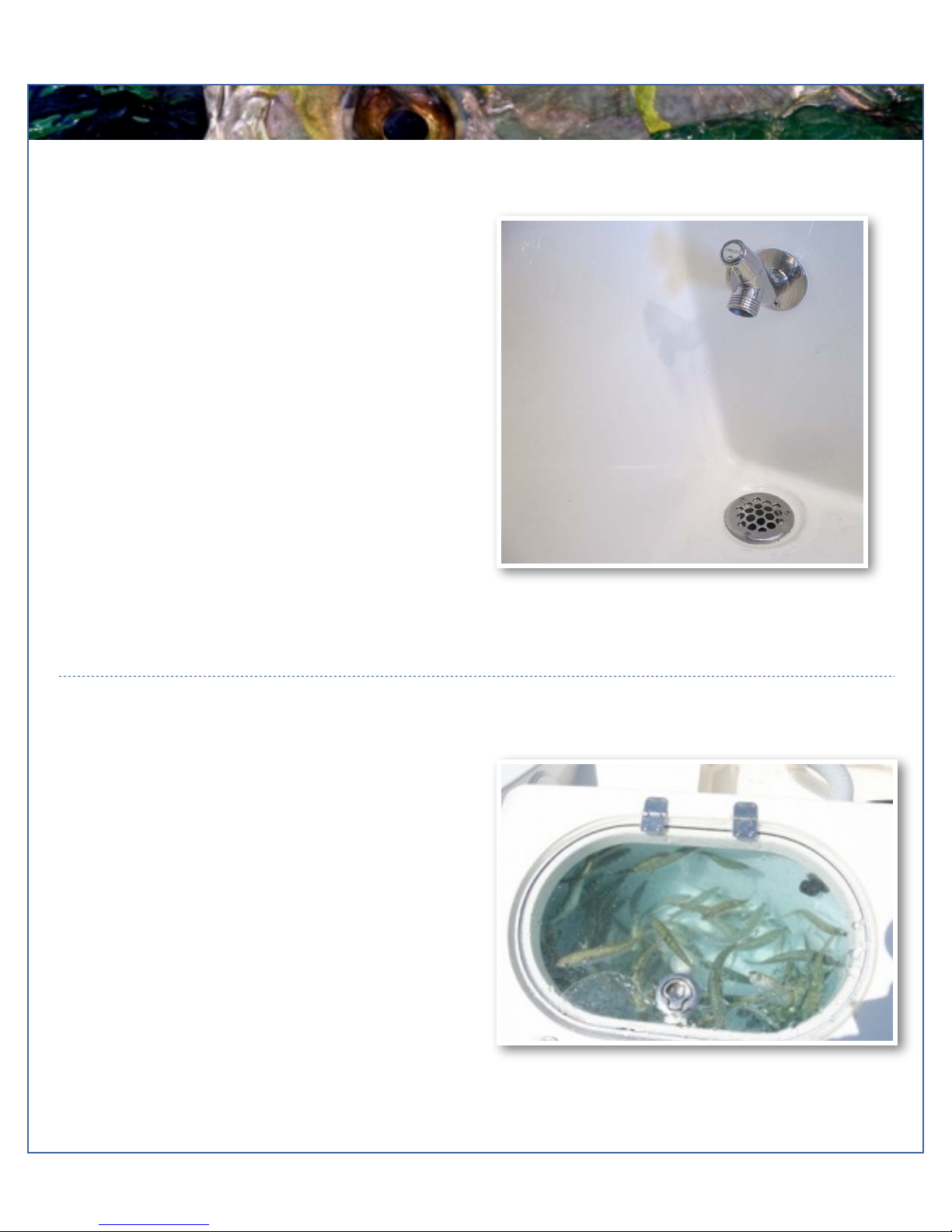
Livewell System
The livewell system is designed to keep your baitfish alive and strong for as long as possible. This livewell provides a cool,
clean, and oxygenated environment that allows you to keep
your baitfish alive for long periods of time. To efficiently
operate your livewell, the following steps should be taken:
1. Open livewell hatch.
2. Screw standpipe into drain at the bottom of the
well.
3. Ensure livewell pump ball valve is in open
position.
4. Turn on livewell switch.
The livewell operates by pumping fresh seawater from the
pump through an aerator head into the livewell. Drainage is
achieved through the grate on the top of the standpipe, which
while unobstructed, will limit the water level to the standpipe’s
highest point. A shorter standpipe can be used to keep less
water in the well. This constant drainage keeps up water flow and allows for the removal of ammonia from the livewell,
therefore extending the life of your baitfish. To drain the livewell, switch off the pump, close pump ball valve, and remove
standpipe.

Model Year 2016 page !18
Maverick Boat Company, Inc. • 3207 Industrial 29th St. • Fort Pierce,
Florida 34946 • (772)-465-0631 or (888)-shallow • Fax: (772) 489-2168
ROD LOCKERS & FISH LOCKERS
Rod Racks
The 277 CC model comes standard with under gunnel rod racks on both the port and starboard sides. These give you
space to safely store an additional 6 rods for your fishing needs. These lockers can also double as storage for various
other items.
Port and Starboard Fish Lockers
The 277 CC has two 47 gallon fish lockers built into the aft cockpit floor on the port and starboard sides. These are
insulated, and each connected to a macerator with the contents being dumped overboard. The macerators are located
in the bilge on the inboard sides of the stringers. They can be accessed through the bilge access hatch under the aft
folding seat. All lockers/hatches come standard with gas shocks to assist in opening and holding the latch open while
loading or unloading.
Starboard Gunnel Storage Rack
Port Fish Locker

Model Year 2016 page !19
Maverick Boat Company, Inc. • 3207 Industrial 29th St. • Fort Pierce,
Florida 34946 • (772)-465-0631 or (888)-shallow • Fax: (772) 489-2168
ANCHOR LOCKER/PHENOLIC PLATES
Anchor Locker/Rode Storage
The anchor locker is located at the bow of the boat and is accessible through the anchor locker door or hatch (photo
below). There is an eye mounted to the bow eye to secure your anchor rode or chain to. After setting your anchor, the
excess rode can remain stored in the locker. The notch supplied in the door allows you to securely close the locker by
aligning your rode through the notch. Optional Windlass is shown on page 31-32.
Table Lift
The 277 CC features an electric table lift in the bow seating area that comes standard with the boat. The table can be
lowered all the way down to sit flush with the deck allowing full access to the bow area (1). It can be raised halfway to sit
flush with the rest of the bow seating for an elevated viewing platform or simply more area to lounge (2). Lastly, at the fully
extended position, it functions as a picnic style table with seating all around (3). The table lift switch is located just behind
the starboard side backrest in the bow seating area.
1
2
3
Model Year 2016 page !20
Maverick Boat Company, Inc. • 3207 Industrial 29th St. • Fort Pierce,
Florida 34946 • (772)-465-0631 or (888)-shallow • Fax: (772) 489-2168
TRIM TABS
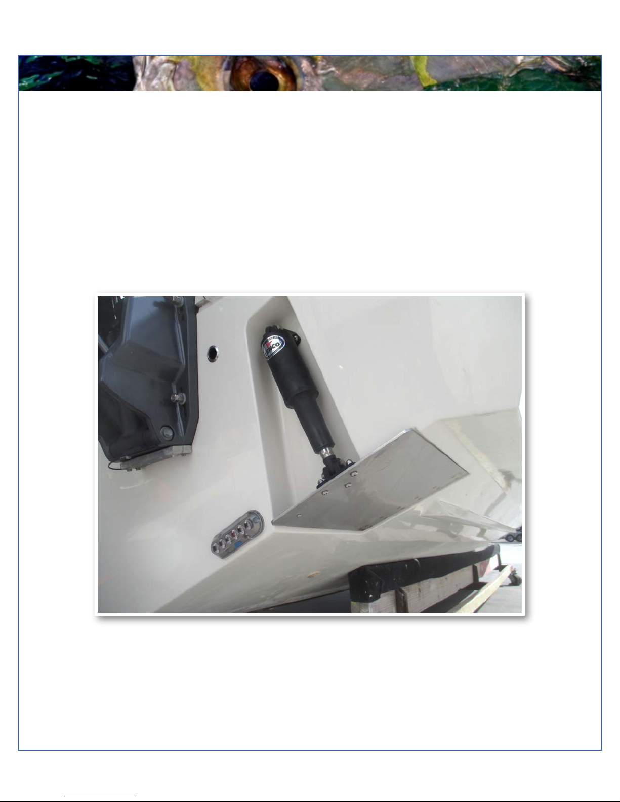
Trim Tab
Trim Tabs
Trim Tabs are standard on your new Cobia. Integrated electric trim tabs can enhance the performance of your boat.
The tabs are electric and therefore do not require a trim tab pump. By not having a pump, there is no possibility of fluid
leaks from a pump.
Trim tabs allow for maximum boat performance, and are great for balancing weight in the boat. They also allow the
boat operator to lift or lower the hull to accommodate for different running situations.
For the operation of trim tabs, note that the port trim tab switch will affect the port side of the boat, and the starboard
switch will affect the starboard side. To lower a particular side, press the top of the corresponding switch down.
Pressing the top of both switches down will lower the bow evenly. To raise the bow, press the bottom of the
corresponding switch.
Table of contents
Other COBIA Boat manuals

COBIA
COBIA 240 CC User manual

COBIA
COBIA 320 CC User manual

COBIA
COBIA 237 CC 2014 User manual

COBIA
COBIA 240 DC User manual

COBIA
COBIA 301CC User manual

COBIA
COBIA 296 CC 2014 User manual

COBIA
COBIA 2012 296 CC User manual

COBIA
COBIA 344 CC User manual

COBIA
COBIA 262 CC User manual

COBIA
COBIA 330 DC User manual


Popular Boat manuals by other brands

Grady-White Boats
Grady-White Boats Freedom 307 owner's manual

Quicksilver
Quicksilver 555BR owner's manual

Yamaha
Yamaha WaveRunner FZR SVHO 2016 Owner's/operator's manual

Williams
Williams Turbojet 285 Owner's handbook

Northern Diver
Northern Diver SRE DS320 manual

LDC Racing Saliboats
LDC Racing Saliboats RS700 owner's manual


