Jet TG-400 User manual

.lET
EQUIPMENT & TOOLS
OPERATOR'S MANUAL
TG-400 TOUCH-UP SPRAY GUN
~
"~
Stock No. M-228174
.lET EGUIIIIMENT a TOOLS, INC.
A W"H. Waller Meier Holding Company PO. BOX1477 / 1901 JEFFERSON AVENUE
TACOMA, WASHINGTON 98401-1477 [206] 572-5000
FAX1-206-383-8705
J
"
Revised 6/92

-Important Information -
1YEAR
LIMITEDWARRANTY
JEToffersa oneyear
warrantyon all products
.
REPLACEMEN:riPARTS.
Replacementpartsfor this tool are availabledirectlyfrom JET Equipment& Tools.
To place an order call 1-800-274-6844. Pleasehave the following information ready:
1. Visa, MasterCardor DiscoverCard number
2. Expirationdate
3. Part number listedwithin this manual
4. Shipping address other than a Post Office box
REPLACEMENTPARTS.WARRANTY.
JET Equipment &Tools makesevery effortto assure thatparts meet highquality and dura-
bility standards andwarrants to the original retailconsumer/purchaserof our parts that each
such part(s) be free from defects inmaterialsandworkmanshipfor a periodof thirty (30)
days from the date of purchase.
~ROOF OF PURCHASE.. .
Please retain your dated sales receiptas proofof purchase to validate the warranty period.
LIMITED TOOL AND EQUIPMENT WARRANTY.'
JET makes every effort to assure that its products meet high quality and durability standards and warrants to the
original retail consumer/purchaser of our products that each product be free from defects in materials and
workmanship as follows: 1 YEAR LIMITED WARRANTY ON ALL JET PRODUCTS. Warranty does not apply to
defects due directly or indirectly to misuse, abuse, negligence or accidents, repairs or alterations outside our
facilities or to a lack of maintenance. JET LIMITS ALL IMPLIED WARRANTIES TO THE PERIOD SPECIFIED
ABOVE FROM THE DATE THE PRODUCT WAS PURCHASED AT RETAIL. EXCEPT AS STATED HEREIN,
ANY IMPLIED WARRANTIES OR MERCHANTABILITY AND FITNESS ARE EXCLUDED. SOME STATES DO
NOT ALLOW LIMITATIONS ON HOW LONG THE IMPLIED WARRANTY LASTS, SO THE ABOVE LIMITATION
MAY NOT APPLY TO YOU. JET SHALL IN NO EVENT BE LIABLE FOR DEATH, INJURIES TO PERSONS
OR PROPERTY OR FOR INCIDENTAL, CONTINGENT, SPECIAL OR CONSEQUENTIAL DAMAGES ARISING
FROM THE USE OF OUR PRODUCTS, SOME STATES DO NOT ALLOW THE EXCLUSION OR LIMITATION
OF INCIDENTAL OR CONSEQUENTIAL DAMAGES, SO THE ABOVE LIMITATION OR EXCLUSION MAY
NOT APPLY TO YOU. To take advantage of this warranty, the product or part must be returned for examination,
postage prepaid, to an authorized service station designated by our Tacoma office. Proof of purchase date and
an explanation of the complaint must accompany the merchandise. If our inspection discloses a defect, JET will
either repair or replace the product or refund the purchase price, if we cannot readily and quickly provide a repair
or replacement, if you are willing to accept such refund. JET will return repaired product or replacement at JET's
expense, but if it is determined there is no defect, or that the defect resulted from causes not within the scope of
JET's warranty, then the user must bear the cost of storing and returning the product. This warranty gives you
specific legal rights, and you may also have other rights which vary from state to state.
JETEquipment&Tools,P.O.Box1477,Tacoma,WA98401-1477:(206)572-5000.

Your new model Spray Gun is normally used for touch-ilp,
stenciling and small work spraying. Like any other fine
precision instrument, its most efficient operation depends
on a knowledge of its construction, operation, and main-
tenance. Properly handled and cared for, it will produce
beautiful, uniform finishing results long after other spray
guns have worn out.
TYPESOF INSTALLATION
).1~~ _A"',,',,
d:f~~ l
f1"",,~.
l_j SiphonCup
SIPHON FEED CUP HOOKUP
Ot! and W.,'
E.tractor
Oil and Water
E .tractor
Air
Prl'ssure Cup
PRESSURE FEED CUP HOOKUP
Air pressure for atomization is regulated at extractor;
fluid pressure at cup regulator. For heavy fluids and
internal mix nozzle spraying. fluid adjusted by control
screw on gun'-
Pressure cup also available less regulator.
FluId
PRESSURE FEED TANK HOOKUP
(Single regula tor)
Air pressure for atomization is regulated at extractor.
fluid pressure at tank regulator.
A.. Sor>r>ly
Pr.ssure Tank
FluId
PRESSURE FEED TANK HOOKUP
(Double regulator)
Air pressure for atomization and fluid supply is
by two individual air regulators on tank rcgulatcJ
~~
nr;~r.
Fluid FluId'
PRESSURE FEED CIRCULATING HOOKUP
Air pressure atomization regulated at extractor. Fluid
pressure regulated at fluid regulator.

GUN HANDLING
Th~ first requirement for a good resultant finish is the
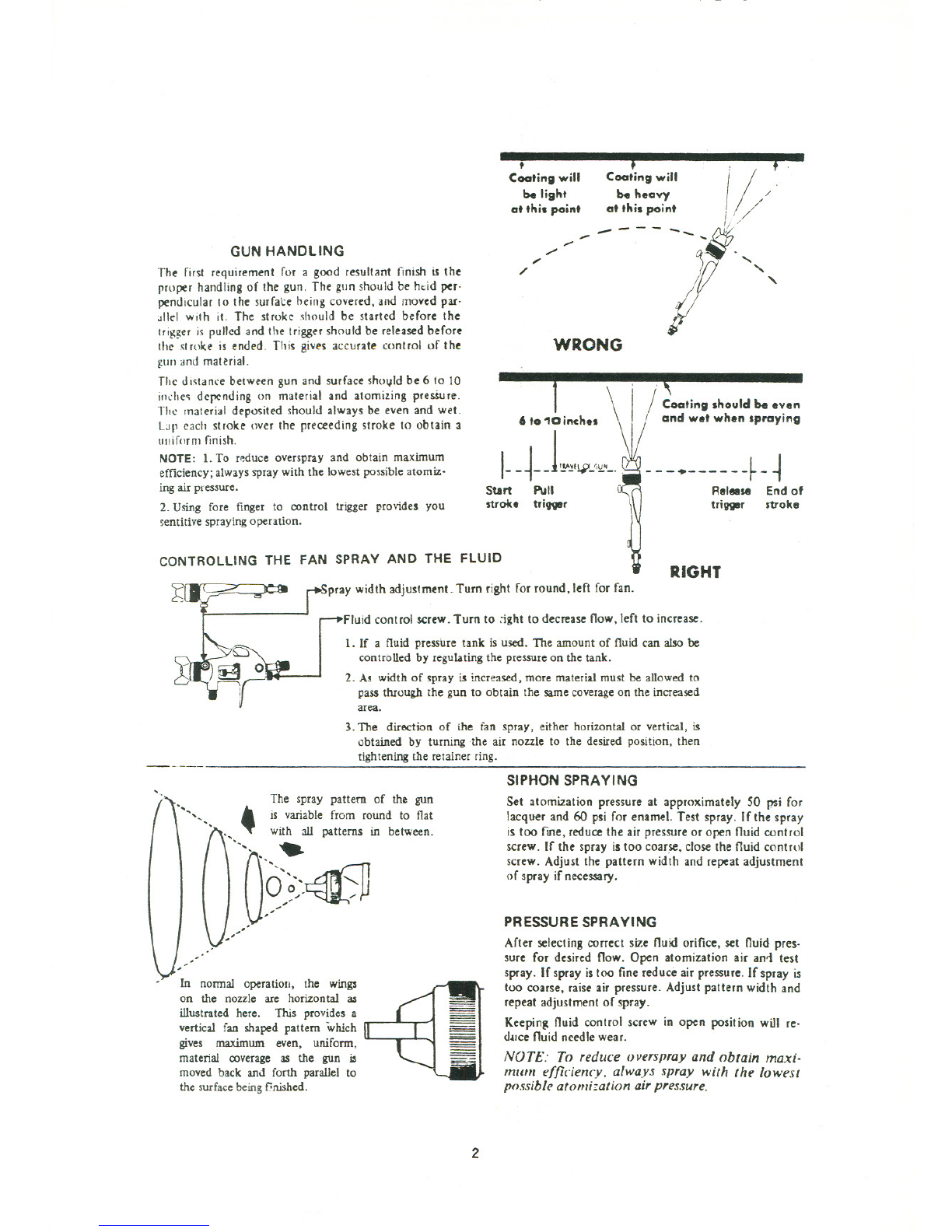
proper handling of the gun. The gun should be hdd per-
pendicular to the surfate heing covered, and moved par-
allel with it. The stroke should be started before the
Irigger is pulled and the trigger should be released before
the st roke is ended. This gives accurate control of the
gun and material.
The distance between gun and surface shovld be 6 to 10
inches depending on material and atomizing presSure.
TII\: material deposited should always be even and wet.
Lap each stroke over the preceeding stroke to obtain 3
uniform finish.
NOTE: 1. To rp-duce overspray and obtain maximum
efficiency; always spray with the lowest possible atomiz-
ing air pressure.
2. Using fore finger to control trigger provides you
sentitive spraying operation.
CONTROLLING THE FAN SPRAY AND THE FLUID
-.
Coetting will
be light
at this point
,
Coetting will
be heavy
at this point I
'!/""
. /
1///
!/ .'
....
/'
./
"
/'
----
"-"- "
WRONG
1"\
\I/Coating should be even
",'0;Mh.. \! a.d wolwho. ,;..
1- _~__L,IV~C'_~
' - - --~ - ~
Start Pull Release End of
stroke tri1Xl8r \trigger stroke
pray width adjustment- Turn right for round, left for fan. RIGHT
Fluid cont rol screw-Turn to ;jght to decreaseflow, left to increase.
1. If a fluid pressure tank is used. The amount of fluid can also be
controlled by regulating the pressure on the tank.
2. As width of spray is increased, more material must be allowed to
pass through the gun to obtain the same coverage on the increased
area.
3. The direction of the ian spray. either horizontal or vertical, is
obtained by turning the air nozzle to the desired position, then
tightening the retainer ring.
'. SIPHON SPRAYING
"'" "
The spray pattern of the gun
.is variable from round to flat
. ~ with all patterns in between.
"'" ......
~s~~~-.~
,'''
.In normal operation, the wings
on the nozzle are horizontal as
lius trated here. This provides a
vertical fan shaped pattern which
gives maximum even, uniform,
material coverage as the gun is
moved back and forth parallel to
the surface being finished.
Set atomization pressure at approximately 50 psi for
lacquer and 60 psi for enamel. Test spray. If the spray
istoo fme,reducetheairpressureor openfluid control
screw. If the spray is too coarse, close the fluid control
screw. Adjust the pattern width and repeat adjustment
of spray if necessary.
PRESSURE SPRAYING
Afterselectingcorrectsizefluidorifice,set fluidpres-
sure for desired flow. Open atomization air an.J test
spray. If spray istoo fine reduce air pressure. If spray is
too coarse,raiseair pressure.Adjustpatternwidth and
repeat adjustment of spray.
Keeping fluid control screw in open position will re-
duce fluid needlewear.
NOTE: To reduce overspray and obtain maxi-
mllm efficienc:v. always spray with the lowest
possible atomization air pres.sure.
2

FAUL TV SPRAV (and how to correct them)
A faulty spray is caused by imporper cleaning or dried material around the
fluid nozzle tip or in the air nozzle. Soak these parts in a solvent that will
soften the dried material and remove with a brush or cloth. Never use
metal instruments to clean the air or fluid nozzles. These parts are care-
fully m~chined and any damage to them will cause a faulty spray. if
either the air nozzle or fluid nozzle is damaged, the part must be replaced
before a perfect spray can be obtained.
PATTERN
~
SPITTING
CAUSE CORRECTION
Dried material in side.
port" A" restricts passage
of air. Greater flow of air
from cleaner side-port
uB" forces fan pattern in
direct ion of clogged side.
A
ff<~
U
'
I<'
.J,~/)/))/. .
"l~
Dissolve materia! in side-polts with
thinn;r. tilen blow ~un clean. Do not
poke into openin~s with metal instru.
ments.
B
Dried material around
the outside of the fluid
nozzle tip at position
uC" restricts the passage
of atomizing air at one
point through the center
opening of air nonle and
results in pattern shown.
This pattern can also be
caused by loose air no7.-
zle.
fj~
....
'-d
Remove air nozzle and Wipe off iluid
lip, using rag wet with thiuner. Ti~ht-
en air nozzle.
A split spray or one that is
heavy on each end of a fan
pattern and weak in the mid-
dle is usually caused by (I)
too high an atomizal1on air
pressure, or (2) by attempting
to get too wide a spray with
thin mat-erial,
Reducing air pressure will correct
cause (I). To correct cause (2), open
material control to full position by
turning to left. At the sametime,turn
spray width adjustment to righl. This
will reduce width of spray but willcor.
rect split spray pattern,
(I) Dried out packingarol;nd
material needle valvepermits
air to get into fluid p2Ssage.
way. This results in spitting,
(2) Dirt between fluid nonle
seat :md body or !ooselyin-
stalled fluid nozzlewill make
gun spit.
(3) A loose or defective swiv-
el nut on siphon cup or ma-
teria) hose can causespitting.
To correct cause (I)
back up knurled nut
(E), place two drops
of machine oil on
packing, replace nut
and lighten with fing.
ers only. In aggra-
vated cases, replace
packing,
To correct cause (2), remove fluid noz-
zle (F), clean back of nozzle and no7..
zle seat in gun body using rag wet with
thinner, replace nozzle and draw up
tightly against body.
To correct cause (3), tighten or re-
place swivel nut.
.
~
3

.JET
EQUIPMENT & TOOLS
TG-400
Touch Up Gun
517
PART#DESCRIPTION OTY PART# DESCRIPTION OTY
501 STEM 1543 SPRING
502 BODY 1544 SCREW
503 PACKING 1 545 VALVENUT
504 RING 1 549 SPRING
505 SPRING 1 551 TRIGGER
506 RING 1 556 CAP
507 PIN 1 557 AIRCONNECTION
508 CONNECTION 1 5232 AIRNOZZLE
509 TRIGGERSCREW 1 5237 NEEDLEASSEMBLY
514 FLUIDNOZZLE 15240 STEMASSEMBLY
517 BODY 1 5241 SIDEPORTCONTROLASSY
530 PACKING 4 700 CUp*
537 LOCK NUT 1 701 CUPCOVER*
538 REARLOCKNUT 1702 GASKET*
* NOTSHOWNON DIAGRAM
RPK-400 Repair Kit: Contains part # 503, 509, 530, 543
RBK-400 Rebuild Kit: Contains part # 544, 549, 551, 5240, 5237 7/94
4

General Maintenance
SPRAY GUN
I. Immerse only the front end of the gun until solvent
just covers the fluid connection.
2. Use a bristle brush and solvent to wash off accumu-
lated paint.
3. Do not submerge tHe entire spray gun in solvent be-
cause:
a. the lubricant in the leather packings wiJldissolve
and the packings willdry out.
b. the lubricant at wear surfaces willdissolvecausing
harder operation and faster wear.
c. residue from dirty solvent may clvg the narrow air
passagesin the gun.
4. Wipedown the outside of the gun with solvent damp-
ened rag.
S. Lubricate gun daily. Use a light machine oil on:
a. fluid needle packing.
b. air valvepacking.
c. side port control packing.
d. triggerpivot point.
Coat the fluid control springwith vaseline.
6. Caution: Neveruse lubricanIScontaining silicone.This
material may cause finish defects.
PRECAUTIONARY NOTE
All parts on a spray gun should be screwed in hand tight
at first; this will avoid the possibility of cross threading
the parts. If the parts can not be turned by hand easily,
make sure you have the correct parIs. unscrew, realign,
and try again. NEVER use undue force in mating parts.
AIR NOZZLE, FLUID Po!OZZLE,NEEDLE ASSEMBLY
I. All nozzles and needles are precision made. They
sh<)uld be handled with care.
2. Except as described in S., do not make my alterations
in the gun. To do so could cause finishing difficulties.
3. To clean nozzles, soak them in solvent to dissolve any
dried material, then blow them clean with air.
4. Do not probe any of the holes in the noules with
metal instruments. If probing is necessary, use only a
tool that is softer than brass.
S. Adjust the fluid needle valve so that when gun is
triggered, air-flow occurs before f1'Jid-flow.
POINTERS ON CLEANING
WHEN USED WITH A CUP
A compatible solvent should be siphoned through gun by
inserting tube from siphon cup in an open container of sol-
vent. Trigger gun intermittently to thoroughly flush' pas-
sageways and internal parts.
WHENUSEDWITHPRESSURE CUP
Shut off the air supply to the Pressure Tank and release the
pressure in the tank. Hold a piece of cloth over the gun
nozzle and pull the trigger, the air will back up through the
fluid nozzle and force the fluid out of the hose and into the
tank. Remove paint from tank, clean tank and put enough
compatible solvent into the tank to clean the hose and gun
thoroughly. Spray this through the gun triggering the gun
intermittently until it is clean, then blowout the fluid hose
to dry it and remove all traces of materials by attaching it
to the air line.
5

AIR SUPPLY
1/111111111111/1111/111111/1/'::'f /'::.11/1/1//'!.-I.!!1/1/1 ~
Pitch pipe bock toward air Nellvlr .
Compressor unit PIPE SIZE. 1.0. line"'" I
InUl II dr.ln It
..eh low point
\011and water
I.trador ."
Drain
r25 FEETORMORE .,
Oillltd WI- EatrKto, 8houldt. It II., 25 ft. f,om ml eomp.-or. F.rth., jf poIIibli.
The oil Ind _tel' e.trlC1or should not be mounted on
or nllr the lir compressor.
The temperatureof air isgreatlyincreasedduringcom.
pression. }.j the air cools down to room temperature, in
the air line. on its way to the spray 2'Jn, the moisture
contained in it condenses.Thus, for maximumeffective.
ness, the oil and water extractor should be mounted at
some point in the air supply system where the tempera.
ture of thc compressed air in the line is likely to be
lowest.
Ail linesmust be properly drained
Pitch all air lines back towards the compressor so that
condensed moisture will flow back into the air receiver
where it can be drained ofi. EachlowSoint in an air line
actsasawater.trap.Suchpointsshoul befittedwithan
easily accessibledrain. See diagramahove.
6
Air Flow
CFM
'0 .,..," "" ,,""
20 %0" "''' "''' "'''
30 "" %0" ," ,"
..
O," ," ," ,"
50 ," ," ," ,"
10 ''' ''' "4" l'l,"
Air Consumption
Fuild Nozzle CFM Pat Compres$or Air
Orifice Size at 8" Required Connection
30 psi 50 psi
<p1.8MM 2.8 4.0 8" 1 H.P. W' NPS(M)
(0.75 W)
Table of contents
Other Jet Paint Sprayer manuals