Jetcom CCTV JCK-32CL User manual

Before trying to connect or operate this product, please read this manual completely
INSTALLATION &
OPERATION MANUAL
LAN CAMERA


Table Of Contents
SAFETY PRECAUTIONS .............................................................................3
1. PRODUCT FEATURES.............................................................................4
1.1 PRODUCT INTRODUCTION ....................................................................4
1.2 PRODUCT FEATURES ...........................................................................5
2. DESCRIPTION OF THE FRONT/REAR VIEW.........................................7
2.1 FRONT PANEL AND REAR PANEL ...........................................................7
2.2 TERMINAL BLOCK ................................................................................8
2.3 FLANK PANEL ......................................................................................9
3. INSTALLATION .......................................................................................10
3.1 CONNECTING WITH AN NVR .......................................................10
3.2 CONNECTING WITH A DVR ..........................................................10
3.3 CONNECTING WITH A MULTIPLEXER.........................................11
3.4 UPDATING SYSTEM SOFTWARE.................................................11
3.5 LAN CAMERA CF CARD TROUBLESHOOTING ...................................12
4. Network Configuration ..........................................................................14
4.1 CABLE CONNECTIONS........................................................................14
4.1.1 Connect to a computer .....................................................................14
4.1.2 Connect to a LAN Hub (INTRANET) ....................................................15
4.1.3 Connect to WAN (INTERNET) ...........................................................15
4.2 CONFIGURE YOUR LAN CAMERA NETWORK SETTINGS.....................16
4.2.1 Enable DHCP Function.....................................................................16
4.2.2 Set IP Address ...............................................................................16
4.3 TCP/IP COMMUNICATION SOFTWARE .................................................18
4.4 TCP/IP INSTALLATION .......................................................................19
1

4.5 TCP/IP CONFIGURATION SETTING ......................................................20
4.6 CONNECTION TESTING.......................................................................21
5. Operating Instructions for Image Software and Network..................23
5.1 MICROSOFT INTERNET EXPLORER ......................................................24
5.1.1 Connecting the LAN CAMERA ...........................................................24
5.1.2 Change Image Setting......................................................................26
5.1.4 Change the System Setting ...............................................................35
5.1.5 Change the Application Setting ...........................................................40
5.1.6 Change the CF Card Setting ..............................................................48
5.1.7 PPPoE & DDNS.............................................................................49
5.2 THE LAN CAMERA VIEWER .............................................................52
5.2.1 Introduction to Network Viewer ..........................................................52
5.2.2 Install the Network Viewer in your PC ..................................................52
5.2.3 Login the LAN CAMERA software.......................................................54
5.2.4 The Image Viewer ..........................................................................70
6. SPECIFICATIONS...................................................................................71
7. Function of Client PC ............................................................................72
APPENDIX 1. –SCANIP..............................................................................73
APPENDIX 2. –FAQ ....................................................................................76
2

SAFETY PRECAUTIONS
All the following safety and operational instructions to prevent harm or injury to the operator(s) or
other persons should be read carefully before the unit is activated.
WARNING
To prevent fire or shock hazard, avoid exposing this unit to rain or moisture.
Do not block ventilation openings.
Do not place anything on top of the unit that might spill or fall into it.
Do not attempt to service this unit yourself, as opening or removing covers may
expose you to dangerous voltage or other hazards. Please refer all servicing to
qualified professional personnel service personnel.
Do not use liquid cleaners or aerosols for cleaning.
To prevent fire or electric shock, avoid overloading wall outlets or extension cords.
This unit must be grounded to reduce the risk of electric shock hazard.
CAUTION
Danger of explosion if the Lithium battery (RTC Battery) is incorrectly replaced.
There is a danger of explosion if the battery is incorrectly replaced. Replace only with
the same or an equivalent type recommended by the manufacturer. Dispose of used
batteries according to the manufacturer’s instructions.
3

1. PRODUCT FEATURES
1.1 Product Introduction
The LAN CAMERA is a state-of-the-art equipment of technological sophistication in its field. It
combines multiple digital technical capabilities with the internal network functions of the network
video camera. The user can immediately connect with a standard network, and the device can
transmit the digital images to a remote browser. The LAN CAMERA is unlike the Web CAMERA,
which connects the USB port or communication port with a personal computer. Since the various
types of the Web CAMERA must initially be connected and installed with a personal computer,
the Web CAMERA is limited regarding some practical applications. Surveillance by remote
control is a principal function of the LAN CAMERA, and this surveillance can be maintained by
digital network recording and direct Internet seeding. By using the LAN CAMERA you can
increase your surveillance capabilities and help yourself monitor your store, your house, factory,
school, public space, and so forth. You can set up different size frames and image quality
categories in accordance with your requirements. Different settings have different picture
qualities and compression ratios to be regulated according to user needs. Connectible
network-attached storages (NAS) are used as digital-mode storages without the problems of
consolidating and supporting different Networks (Windows 95/98/NT/2000, Macintosh, Novell
and Unix). Digital images are more convenient than analogs for search and delivery functions,
and enable you to access the latest status instantly. The user can moreover use multiple modes
of accessing images, such as schedule, time, and alarm.
The LAN CAMERA is a user-friendly product whose simplified installation and setup procedures
make it easy to apply and handle. Additionally it provides all-weather automation-monitored
control. Installation will automatically start up the LAN CAMERA, which further supports by
default without disrupting the existing network clients. The user need only start up a browser
such as the Microsoft Internet Explorer, and proceed with the connections.
4

1.2 Product Features
An inbuilt Web Server and Network Interface. The LAN CAMERA is effective in assuring the
safety of an independent digital camera.
Dual purpose: the LAN CAMERA can simultaneously export both the traditional analogs
and the digital images.
Motion detection: You can select the range and sensitivity of the detection.
The user can utilize the support Java browser and directly view the general appearance of
a picture, and can also set the browser.
1/ 3 inch interlaced CCD (charge - coupled device).
380000 pixels. 768x495(NTSC), 752x582(PAL)
480 TV lines.
Adjustable C / CS mount.
Automatic white balance (AWB) available、Automatic gain control (AGC) 、Backlight
Compensation (BLC)、Electronic shutter speeds :
(NTSC:1/50-1/10000 sec. PAL:1/60-1/10000sec).
The sensitivity is 1-2,000,000 Lux.
Image compression:MJPEG.
There are 5 levels of image quality the user can select from:Lowest, Low, Medium, High,
and Highest.
There are 4 different Resolution rates the user can choose from:
【NTSC :352x240,720x480(Frame),720x240,720x480(Field) 】
【PAL :352x288,720x576(Frame),720x288,720x576(Field) 】
The user can regulate the categories of Brightness, Contrast, Saturation, Hue, and Camera Title.
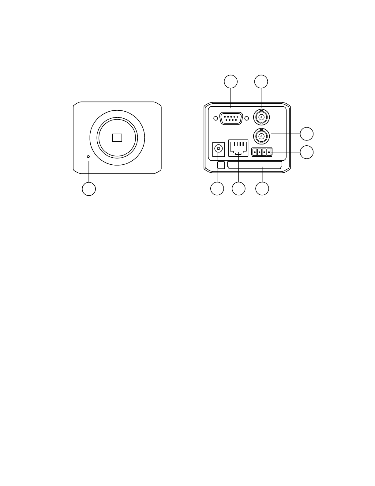
A pair of RJ-45 Fast Ethernet 10 / 100 Base-TX ports. The LAN CAMERA connects an
Ethernet cable to the network cable connector located on the Internet Camera’s rear panel
and attaches it to the network.
Protocol for remote control.
Networking:TCP/IP, DHCP, HTTP, UDP, FTP, SMTP, SNTP, NetBIOS, ICMP, DDNS, DNS.
Alarm sensor Input/Output Terminals.
Digital mode saves images via E-mail and FTP.
5

The RECORD–SCHEDULE provides seven periods of time and the LAN CAMERA starts
and stops recording according to the programmed schedule.
The device will record as long as the alarm input is activated, and allow users to set the
alarm for a certain duration.
The LAN CAMERA permits users to set the date and time.
The LAN CAMERA enables users to set the administrative status account and password.
There are 3 levels of users’ accounts:Admin, Operator, Viewer. The total number of users’
account included under these 3 levels is ten.
Time-Lapse and Real-Time recording are featured options.
The device is capable of working with various known multiplexers and quad processors.
RS-232 / RS-485 communication port.
Distribution of live and recorded images through the TCP/IP network environment.
Watchdog:In the event of any malfunction, the Watchdog immediately alerts the LAN
CAMERA, which will restart operation automatically.
The LAN CAMERA can automatically check the time with the SNTP via the Internet.
The device has a microphone installed in its front panel which records sound.
Built-in CF card slot for copying image to CF card.
Update with CF card.
6

2. DESCRIPTION OF THE FRONT/REAR VIEW
2.1 Front Panel and Rear Panel
-- Front Panel -- -- Rear Panel --
176 8
2 3
4
5
RS-232
DC 12V
ETHERNET
CF CARD
1 2 3 4
1. ALM. OUT
2. GND
3. ALM. IN
4. ALM. RECOVER
VIDEO OUT
AUDIO OUT
1. MICROPHONE:
The LAN CAMERA has an additional audio function. The device has a microphone built into its
front panel which records sound.
2. RS-232 Port:
The RS-232 communication port functions as a connector to an external control device.
3. VIDEO OUT Connector:
The connector provides the unit’s composite video signals to a monitor.
4. AUDIO OUT:
This provides the unit’s audio signal to a speaker.
5. ALARM I/O:
This is a 4-PIN D-SUB connector including ALARM OUT, GROUND, ALARM IN, and ALARM
RECOVER for connecting with external devices. Please refer to the next section for details.
6. Plug Inlet:
The inlet connects to an external power supply. Connect to the provided AC adapter.
7. ETHERNET 10/100 Connector:
This is one standard RJ-45 connector for 10/100 Mbps Ethernet networks.
8. CF CARD Slot:
This is used for system software updating and archiving / accessing critical images.
7

2.2 Terminal Block
1. ALM. OUT
2. GND
3. ALM. IN
4. ALM. RECOVER
1. ALARM OUT (OUTPUT): This is an alarm output trigger. Connect this to external
devices such as buzzers or lights. (
5V, 20mA
0V(Active) )
2. GND: Ground contact.
3. ALARM IN (INPUT): This is an alarm input that can be programmed in the menu
system to active low. (
5V, 20mA
0V(Active) )
4. ALARM RECOVER (INPUT): This pin connects to an alarm-clear device for clearing an
alarm. (
5V, 20mA
0V(Active) )
8

2.3 Flank Panel
ALC
LENS
POWER LAN
1 AES
2 DC IRIS
3 DHCP
4 STATIC IP
RS-485
7621 3 4 5
1. Lens Mount: This LAN CAMERA can be used with either C or CS mount lens.
2. IRIS: Auto iris connector.
This camera works with DC drive auto iris lens. Please refer to the pin assignment
marked on the camera when connecting the auto iris lens.
3. ALC VR: Iris control VR.
When an auto iris (DC Drive) lens is used, this VR is used to adjust the iris for different
lighting environments. Adjust the VR clock-wise to open the iris and counter-clockwise
to close the iris of the camera.
4. DIP Switch:
1. AES: Auto electric shutter.
2. DC IRIS: Use auto iris (DC drive)
3. DHCP: Turn On / Turn Off the DHCP protocol. The switch points
upwards, the device can change the setup of network function
(enable/disable) via the network.
4. STATIC IP: The switch points down, the device can’t change the
setup of network function (enable/disable) via the network.
5. RS-485: Supports the RS-485 protocol.
6. POWER Indicator:Indicates the power status of the unit. The green light indicates the
unit is activating. The red light indicates the power cannot move. If the CF Card is
withdrawn in this mode, the card will break.
7. LAN Indicator: Indicates the LAN status of the unit. The green light indicates the 100
Mbps Ethernet network is activating. The red light signals the LAN is data linking.
9

3. INSTALLATION
Please follow the instructions and the diagram below to set up the system.
NOTE: The LAN CAMERA is linked by its Video Out connection via a BNC connector to a
monitor's Video In connection. If this connection is there, you can see some information
on the monitor screen, such as the LAN CAMERA factory default Static IP
address(192.168.1.168). But the LAN CAMERA Static IP address can only appear if
there is a connection between the LAN CAMERA and another device. If there is no such
connection, the LAN CAMERA factory default Static IP address will not appear on the
monitor screen.
3.1 CONNECTING WITH AN NVR
Use a crossover LAN cable to connect directly to a NVR.
SD Card
RS-232
ALARM DC12V
AUDIOVIDEO
OUT
OUT
I/O
RS-485
ETHERNET
10/100
LAN CAMERA
CONNECT TO ETHERNET
RJ45 CONNECTOR
CONNECT TO NVR
ETHERNET PORT
3.2 CONNECTING WITH A DVR
SD Card
RS-232
ALARM DC12V
AUDIO
IN
IN
OUT
OUT
VIDEO
TO
MONITOR
TO
MUX'S VCR IN
FROM MUX
MAIN MONITOR
I/O
RS-485
ETHERNET
10/100
LAN CAMERA
CONNECT TO VIDEO OUT
BNC CONNECTOR
CONNECT TO DVR
VIDEO IN
10

3.3 CONNECTING WITH A MULTIPLEXER
LAN CAMERA 1
LAN CAMERA 2
LAN CAMERA 16
TO LAN CAMERA VIDEO OUT BNC CONNECTOR
3.4 UPDATING SYSTEM SOFTWARE
If the system software of the LAN CAMERA needs to be upgraded, please take the following
steps to safely update it.
Important: Before carrying out the following procedures, please ensure the CF card is
working and the file of system firmware is intact
1. Format a CF Card using FAT16 format if it is unformatted; there is no limitation on a CF Card’s
capacity.
2. Create a directory named LANCAM in the CF Card; if the directory already exists, move to
Step3.
3. Copy the file of UPDATE.BIN to the LANCAM-directory.
4. If the LANCAM is running, please power it off first.
5. Insert the CF CARD into the LANCAM in a face-down position of the front of the CF Card.
6. Remove the Ethernet cable from RJ-45 port and then power on LANCAM.
7. In 5 to 10 seconds, a message of "UPDATE PROCESSING" appears on the screen on a blue
background; if not, please check out Step1 to Step6 carefully or inform your technical support
which ignoring the following steps.
8. DO NOT power off the LANCAM while this update process is running until a text of "UPDATE
OK RESET PLEASE" appears on the screen; this may take 15 to 30 seconds.
9. If a text of "UPDATE NG RESET PLEASE" appears rather than "UPDATE OK RESET
11

PLEASE", please write down the error messages shown on the screen and inform your
technical support, which ignoring the following steps.
10. Turn off the LANCAM when this update process is finished, and remove the CF Card from the
LANCAM.
11. Reconnect the Ethernet cable into the RJ-45 port if necessary.
12. Reboot the LANCAM and it will work normally if the entire update procedure is functioning
correctly.
13. Verify the version of the system software.
Warning:
1. Don’t use FAT32 or NTFS or other file formats in Step1.
2. Step1 to Step3 have to be done on a PC.
3. Make sure the file of UPDATE.BIN is a correct one in Step3, or the LANCAM will not work
normally after being updated.
4. If the power of the LANCAM is suddenly lost in Step8, please remove the CF Card first
and turn the LANCAM on next to test its operation. If the LANCAM remains working
normally, please go back to Step4; oppositely, please inform your technical support.
5. In Step10, if the CF Card is not removed and the LANCAM does not go online as well, the
update process will repeat again after rebooting the LANCAM.
6. Make sure that the CF Card is inserted in a correct position in Step5, or the LANCAM will
suffer permanent physical damage.
7. If a message of "CSUM ERROR" appears in Step8, it implies a problem on the file of
UPDATE.BIN.
8. Don’t Interrupt the process while the unit is updating itself but proceed with a CF card
containing no system software of the unit, as otherwise the unit will crash.
9. Don’t connect the RJ-45 cable while updating the system software of the unit
otherwise the unit will remain inactive.
3.5 LAN CAMERA CF Card Troubleshooting
1. Check if the CF Card position is correct. Please refer to the manual for the listed information.
2. After powering on the LAN CAMERA, insert the CF Card in a correct position. A tiny icon of "CF"
will show up in the upper-right corner of the screen of a monitor. If not, it means the device
detection has failed. Please contact your technical support in this event and ignore the following
12

steps.
3. If no cross sign appears beside the "CF" icon, please go forward to the next step. If a cross sign
appears, please check out the followings:
a. Is it really a CF "Memory" Card?
b. Is this CF Card formatted with the FAT16 format?
c. Connect the CF Card with a PC and test whether the PC can read the data or not?
d. Dose this CF Card still have capacity for storing data?
e. Is the CF Card set to be writable?
If all the answers are "yes" but the cross sign still exists, please contact your technical support
and ignore the following steps.
4. Please make sure the function of "CF CARD ENABLE" is enabled on the ALARM and
SCHEDULE pages if no cross sign appears beside the "CF" icon on the screen.
5. After recording, read the data through the web page of "cfget.htm". If the data cannot be read
through the networks, please read it by a PC instead and check out the data stored in the
"LANCAM" directory and please contact your technical support no matter regardless of whether
there is data or not.
Warning:
1. Performing this troubleshooting process may need a monitor, a PC, a card reader and
some cables.
2. If the CF Card is removed while storing or accessing data, data will be lost.
3. If there is a cross sign beside the "CF" icon, it means the CF Card has been inserted into
the LAN CAMERA but cannot perform the writing function. Possible reasons are:
a. It is not a CF memory card.
b. The CF Card is unformatted or formatted with a non-FAT16 or non-FAT12 format.
c. The file system is damaged.
d. The capacity of the CF Card is full.
e. The CF Card is set to be read only.
4. Shut the power before inserting the CF Card. Otherwise the unit may shut down.
13

4. Network Configuration
4.1 Cable Connections
Please follow the instructions below to connect your LAN CAMERA to a computer or a network
and to choose a proper RJ-45 cable configuration for connections.
Physical specifications of RJ-45 cable for Ethernet
Wire Type Cat. 5
Connector Type RJ-45
Max. Cable Length 30 m
Hub Wiring Configuration Straight Through
PC Wiring Configuration Cross Over
4.1.1 Connect to a computer
Use a crossover LAN cable to connect directly to a computer.
RJ-45
CROSSOVER CABLE
CROSSOVER CABLE PIN CONFIGURATION
LAN CAMERA
TO PC LAN CARD
14

4.1.2 Connect to a LAN Hub (INTRANET)
The RJ-45 PIN configuration for connecting with a LAN Hub is shown below.
RJ-45
LAN CAMERA
TO PC NETWORK CARD
uplink
4.1.3 Connect to WAN (INTERNET)
The RJ-45 PIN configuration for connecting to a WAN is the same as connecting to a LAN.
RJ-45
LAN CAMERA
STATIC IP CABLE/XDSL MODEM
TO ISP
LAN WAN
15

4.2 Configure Your LAN CAMERA Network Settings
Upon connecting with the network hardware, you need to activate the network function and
configure the proper network settings of the LAN CAMERA.
4.2.1 Enable DHCP Function
This function can only work if the LAN which the unit is connected to has a DHCP server. If the
DHCP server is working, the LAN CAMERA will obtain an IP address automatically from the
DHCP server. In that case please skip section 4.2.2 (Set IP address) and follow section 4.3
(TCP/IP Communication Software).
4.2.2 Set IP Address
You need to set an IP address for the unit if the unit isn’t connected to a DHCP server. Otherwise,
please follow the instructions given below:
Set the IP, MASK and GATEWAY. The following is a sample setting.
IP: 192.168.1.X
MASK: 255.255.255.0
GATEWAY: 0.0.0.0
NOTE: When only one unit of the LAN CAMERA is connected to a computer or LAN, you
can freely assign an IP address for the LAN CAMERA. For example, there is a
range of LAN CAMERA IP addresses from 192.168.1.1 to 192.168.1.255. You can
pick one for use from the range of the IP. It’s not necessary to set the MASK and
GATEWAY; leave the settings as default.
When a LAN CAMERA is connected to a WAN, you must acquire a unique,
permanent IP address and correctly configure the MASK and GATEWAY settings
according to your network architecture. If you have any questions regarding
those settings, please contact a qualified MIS professional or your ISP.
NOTE: When connecting to a network, each connected LAN CAMERA must be assigned
a unique IP, which must be in the same class type as your network address. IP
16

addresses are written as four sets of numbers separated by periods; for example,
192.168.1.1 Therefore, if the connected network is identified as Class C, for
example, the first three sets of numbers of the LAN CAMERA IP address must be
the same as the network address. If the connected network is identified as Class
B, the first two sets of numbers of the LAN CAMERA IP address must be the
same as the network address. If you have any questions regarding these settings,
please contact a qualified MIS professional or your ISP.
17

4.3 TCP/IP Communication Software
Follow the instructions below to install the TCP/IP communication program into your computer.
Click the Start menu from your computer, and point to the Settings/Control panel.
Click the Network icon twice to enter the same setting windows.
18
Table of contents