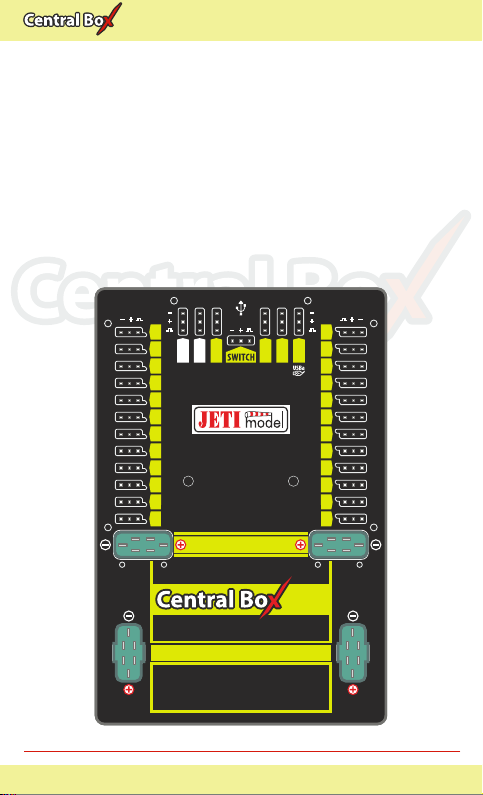
JETI model Central Box 400 User manual

EN
400400400
User Manual
EN
Protected multi-channel servo interface
Modellbau Lindinger GmbH
www.lindinger.at

EN
400400400
1. Introduction ..................................................................................... 3 EN
1.1 Features ................................................................................... 4 EN
2. Description ........................................................................................ 5 EN
3. Connection ...................................................................................... 7 EN
3.1 Power supply of Central Box 400 ........................................... 7 EN
3.2 Advanced power sources settings of the
Central Box 400 ...................................................................... 10 EN
3.3 Overload protection of servos ............................................ 11 EN
3.4 Connecting Central Box PPM variant ............................ 12 EN
3.5 Connecting Central Box EX Bus variant ........................ 13 EN
3.6 Putting the Central Box 400 into operation ...................... 14 EN
3.7 Alternative functions - logical input .................................. 15 EN
3.8 Alternative functions - logical output ............................... 15 EN
3.9 Installing safety mechanism of connectors ..................... 16 EN
4. Configuration via JETIBOX ....................................................... 17 EN
4.1 Actual values .......................................................................... 18 EN
4.2 Minimum / Maximum values ............................................. 18 EN
4.3 Setting ..................................................................................... 19 EN
4.4 Out Pin Set ............................................................................... 20 EN
4.5 Alter. Function ........................................................................ 21EN
4.6 Alarms ..................................................................................... 22 EN
4.7 Recording ............................................................................. 22 EN
1 EN
Modellbau Lindinger GmbH
www.lindinger.at

EN
400400400
4.8 Service information .............................................................. 23 EN
5. Configuration via the DC/DS transmitter ............................. 24 EN
5.1 Settings .................................................................................... 25 EN
5.2 Alternate functions of pins .................................................. 26 EN
5.3 Servo Fail-Safe ....................................................................... 27 EN
5.4 Servo Output Mapping ....................................................... 28 EN
5.5 Telemetry ............................................................................... 28 EN
5.6 Telemetry Min/Max .............................................................. 29 EN
5.7 Recording ................................................................................ 30 EN
6. Data recording ............................................................................... 31 EN
7. Telemetry reading ........................................................................ 31 EN
8. Firmware update ........................................................................... 32 EN
9. Technical specifications of the Central Box ....................... 33 EN
10. Warranty, service and the technical support ....................... 34 EN
2 EN
Modellbau Lindinger GmbH
www.lindinger.at

EN
400400400
The Central Box 400 is a switchboard designed for the complete
management of servos in large to giant models with an emphasis
on safety. The Central Box 400 has a unique design that provides
overload protection at each servo output. An independent, very
powerful BEC (battery eliminator circuit) for each battery input
makes the Central Box an optimal solution to connect up to 24
servos. The Central Box 400 can manage the batteries and fully
supports the JETI EX telemetry system. Up to two receivers with
serial (PPM, EX Bus, UDI) output can be connected to the Central
Box 400. With a JETI DC/DS transmitter, the full potential of the
Central Box can be used, such as easy configuration of the Central
Box, EX telemetry, and very fast servo response.
1 Introduction ENGLISH
FW ver. 1.05, ver.1.0 -2015-05
400400400
3 EN
Modellbau Lindinger GmbH
www.lindinger.at

EN
400400400
1.1 Features
Two independent high-powered BEC´s for voltage
stabilization of servos
overload protection on each channel
overload protection on Rx, Ext, and Switch outputs
possibility to connect up to 2 receivers with serial interface
(PPM, EX Bus, UDI)
built-in Expander function with the possibility to connect JETI
EX sensors
input for magnetic switch or RC switch
batteries connected via MPX connector
stabilized voltage output via a pair of MPX connectors
100Hz mode of servo outputs (10ms period)
supports EX telemetry (voltage, current, capacity, and
temperature measurement, overload indication, ...)
internal memory for storage of telemetry data
USB connectivity for connection to PC
easy settings changes via DC/DS transmitter
firmware updatable
suitable for use with high voltage (HV) servos
robust metal construction with mounting holes
LED status indication
each output is individually configurable (channel assignment,
trim, reverse, ATV)
4 EN
Modellbau Lindinger GmbH
www.lindinger.at

EN
400400400
2 Description
Central Box 400 has 24 outputs for servos with individual
overload protection. More over, outputs Y17-Y24 can be
configured as:
servo output
logical input
logical output
Control signals generated by the Central Box to servos are 5V. This
solution ensures reliable servo signal transfer for longer distances.
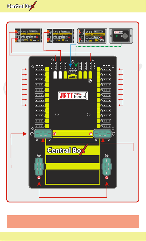
Ext1 - Ext4 ports can be configured for use as:
inputs for telemetry sensors
EX Bus expanders - used for connecting devices which support the
EX Bus protocol (the Central Box, a sensor,...)
Ext4 - slot is also used as an output to connect a JETIBOX to
configure the Central Box and for the firmware update connection
Rx1 - primary input for connecting receivers with serial output (EX,
PPM, UDI)
Rx2 - secondary (backup) input for connecting receivers with serial
output (EX bus, PPM, UDI)
Switch slot is reserved for connecting magnetic switch or RC Switch
BEC output serves as the output for stabilized voltage to power
supply other Central Boxes that can be power supplied from the
Central Box 400. The voltage at the output has the same level as the
voltage for supplying the servos. Voltage for the servo outputs is
adjustable from 5-8V with 0.1V steps.
For more safety, the Central Box 400 contains two BEC regulators
connected in parallel. Information about the correct power supply
and a faultless condition of the individual branches is indicated by
green LED and also by telemetry. It is not recommended to use the
BEC outputs for direct power supply of servos or receivers with
servos. These devices are not individually protected. If one element
of the branch supplied from the BEC output is overloaded, the
5 EN
Modellbau Lindinger GmbH
www.lindinger.at

EN
400400400
24 channel servo interface
BATTERY INPUT
6 -17V
LED1 LED2
Ext4
14
15
16
17
18
19
20
21
22
23
24
Rx 1
Rx 2
Ext1
Ext2
Ext3
2
3
4
5
6
7
8
9
10
11
12
1
BEC OUTPUT
13
400400400
BATT1 BATT2
21
Fig. 1: Central Boxu 400 description
entire branch is disconnected. The BEC output current limit is 15A.
BATT1 and BATT2 battery inputs
To avoid accidentally disconnecting or pulling the cable with the JR
or MPX connector out, e.g. due to vibrations, it is possible to install
safety mechanism for connectors on the Central Box. Safety
mechanism for connectors fixes not only connectors of servos,
receivers, and sensors, but also BEC outputs (MPX connectors), see
chapter Safety mechanisms of connectors
6 EN
Modellbau Lindinger GmbH
www.lindinger.at

EN
400400400
3 Connection
3.1 Power supply of Central Box 400
The Central Box 400 can only be powered from batteries connected
to BATT1 or BATT2. When selecting the power supply it is necessary
to follow the power requirements and the number of the servos you
use. Batteries for power supply must be sufficiently large to prevent
a decrease of the output voltage for servos when loaded (voltage
depression) and to allow the overload protection function properly.
Together, both power supply methods must be able to supply a 20A
continuous and 120A peak current. To take full advantage of
internal BEC we recommend to power the Central Box from three
Lixx cells.
The power batteries are connected to the Central Box using MPX
connectors. The Central Box allows up to two batteries to be
connected. The selection of battery to supply power is based on the
voltage set in individual BEC´s. During use, the power is actually
supplied from the battery whose BEC has higher voltage set. If the
voltage is the same, the power can be used from both batteries at
the same time. This rule applies to the standard power supply. This
means that the power battery voltage should be greater than the
required BEC voltage setting. When the voltage of the batteries is
different, the power is not shared and each pack is isolated from the
other. This allows you to safely use batteries of different capacity,
number of cells, and chemistry type. If the power for the Central Box
is provided only from one battery, it can be connected via either the
BATT1 or BATT2 input.
7 EN
Modellbau Lindinger GmbH
www.lindinger.at

EN
400400400
24 channel servo interface
BATTERY INPUT
6 -17V
LED1 LED2
Ext4
14
15
16
17
18
19
20
21
22
23
24
Rx 1
Rx 2
Ext1
Ext2
Ext3
2
3
4
5
6
7
8
9
10
11
12
1
BEC OUTPUT
13
400400400
BATT1 BATT2
21
Rsat2 (Rx2)
Rsat2 (Rx1)
Ext. Ext.
RC Switch Magnetic Switch
ON ON/OFF
Input Voltage 2-4 LiXX
SERVO standard
SERVO standard
Central Box 100
(standard SERVO)
Output Voltage 6V
Fig. 2: Example of the Central Box 400 powered for the use with
standard servos (voltage range up to 6V)
PPM PPM
8 EN
Modellbau Lindinger GmbH
www.lindinger.at

EN
400400400
24 channel servo interface
BATTERY INPUT
6 -17V
LED1 LED2
Ext4
14
15
16
17
18
19
20
21
22
23
24
Rx 1
Rx 2
Ext1
Ext2
Ext3
2
3
4
5
6
7
8
9
10
11
12
1
BEC OUTPUT
13
400400400
BATT1 BATT2
21
Input Voltage 2-4 LiXX
High voltage SERVO
Central Box 100
(High voltage servo)
Output Voltage 7.4V
Fig. 3: Example of the Central Box 400 power for use with
HIGH Voltage servos
High voltage SERVO
The Central Box can only be power supplied from
BATT1 or BATT2.
Caution:
Rsat2 (Rx2)
Rsat2 (Rx1)
Ext. Ext.
RC Switch Magnetic Switch
ON ON/OFF
PPM PPM
9 EN
Modellbau Lindinger GmbH
www.lindinger.at

EN
400400400
3.2 Advanced power sources settings of the
Central Box 400
In the settings of the Central Box it is possible to adjust the BEC to
the Advanced mode. In this mode you can adjust the voltage of
individual power supplies and thus one source can be used in
preference to the other one. This way you can manage which
battery provides the energy. This can lead e.g. to a situation when
under normal circumstances only one power supply is used. The
other one is intended only as a backup. You achieve this function by
adjusting the supply voltage of BEC1 greater than of the BEC2 or
vice versa. E.g. UBEC1 is 7.4V and UBEC2 is set to the value of 5.5V.
The voltage stabilization of individual power sources can be
deactivated. If the input battery voltage is lower than your settings,
or if there is the same voltage on the BEC and on the input battery,
then the voltage is not stabilized. For example if 6V are used and the
U BEC is set to 8.4V, the voltage of the power supply output is max.
6V, which is not stabilized.
Fig. 4: The block scheme of power supply.
10 EN
BEC1
BEC2
BATT1
BATT2
BEC OUTPUT
SERVO
Mixer
UBEC1
UBEC2
UOUT
Modellbau Lindinger GmbH
www.lindinger.at

EN
400400400
3.3 Overload protection of servos
The Central Box has an overload protection circuit on every servo
output. In case of an overload, the affected servo output is
disconnected from the power supply while the remaining servo
outputs are still powered.
Fig. 5: Correct connection of servos to the Central Box
Caution: It is not recommended:
- to connect more Central Box outputs to one servo
- to use a Y cable (connecting two servos to one
output)
Caution: It is prohibited to connect servos directly to any
receiver that is powered from the Central Box 400
(Rx1 or Rx2). In this case the receiver can be fully
disconnected from the power supply, which could
lead to the signal loss.
NO
SERVO
NO
SERVO
SERVO
SERVO
SERVO
YES
SERVO
Rsat2 (Rx1)
Ext.
SERVO
NO
11 EN
Modellbau Lindinger GmbH
www.lindinger.at

EN
400400400
3.4 Connecting Central Box PPM variant
If you connect Duplex receivers with a possibility to switch the
output to EX Bus to the Central Box, we recommend the wiring
described in chapter 3.5, EX Bus variant.
The receivers can be connected to the Central Box using the Rx1
and Rx2 inputs.
The Ext4 port is for output of telemetry data from the Central Box in
the form of EX telemetry. To use the Central Box telemetry and other
sensors connected to it, use a Duplex EX receiver. Simply connect
the Central Box output labeled Ext4 with the Duplex EX receiver
input labeled Ext.
Configuring the Central Box is done by using a JETIBOX. You can
either directly connect to the Central Box, or wirelessly connect
using transmitter module, or a JETI transmitter.
Rsat2 (Rx2)
Rsat2 (Rx1)
Ext.
RC Switch Magnetic Switch
ON ON/OFF
PPM PPM
Fig. 6: Block diagram of Central Box 400 connection - PPM variant
Sensor
Sensor
Sensor
12 EN
Modellbau Lindinger GmbH
www.lindinger.at

EN
400400400
3.5 Connecting Central Box EX Bus variant
Receivers can be connected to the Central Box using the Rx1 and
Rx2 inputs.
Ext1-4 are inputs for telemetry sensors. Telemetry is transmitted to
the receivers via EX Bus. Ext1-4 can also be configured as EX Bus
outputs. Configuring the Central Box is, in this case, done directly in
the transmitter via EX Bus.
EX Bus output from the Central Box is an input for devices
supporting this standard, such as Central Boxes and certain sensors.
When operating the Central Box with DC/DS transmitter, it is
recommended to use two receivers communicating with the
transmitter in the wireless mode, Double path".
Rsat2 (Rx2)
Rsat2 (Rx1)
Ext.
RC Switch Magnetic Switch
ON ON/OFF
Ext.
Fig. 7: Block diagram of Central Box 400 connection - EX Bus variant
Sensor
Sensor
Sensor
JETIBOX
Sensor
13 EN
Modellbau Lindinger GmbH
www.lindinger.at

EN
400400400
The Central Box can be configured in two ways:
by connecting a JETIBOX (directly to the Ext4 of the Central Box or
wirelessly via a transmitter/transmitter module)
using DS/DS transmitter or via Device Explorer (EX Bus)
3.6 Putting the Central Box 400 into operation
1. Connect the battery to BATT1 or BATT2 input of the Central Box.
2. Connect the bind plug to the Ext. pin of the auxiliary receiver.
3. Use a three-wire cable to connect PPM output of the receiver
and the Rx1 input of the Central Box.
4. Switch on the DC/DS transmitter. Then the transmitter is paired
with the receiver.
5. Disconnect the bind plug from the receiver. Reconnect the
three-wire cable connecting the receiver with the Central Box.
Disconnect the cable from the PPM output of the receiver and
connect it to the Ext. output of the receiver.
6. In the transmitter menu Menu->Advance Properties
->Wireless modules/Trainer switch the mode to Double
path.
7. Connect the bind plug to the Ext. pin of another auxiliary
receiver.
8. Use a three-wire cable to connect PPM output of the receiver
with the Rx2 input of the Central Box.
9. In the transmitter menu Menu->Advanced Properties
->Wireless modules/Trainer confirm the item Pair the
secondary TX module.
10. After pairing the transmitter with the other receiver, disconnect
the bind plug from the receiver. Reconnect the three-wire cable
connecting the receiver with the Central Box. Disconnect the
cable from the PPM output of the receiver and connect it to the
Ext. output of the receiver.
11. In the transmitter menu Menu->Model ->Device Explorer
select your auxiliary Rx from the first line and set Serial link to
EX Bus & PPM pos.. Follow the same procedure when setting
the second receiver.
14 EN
Modellbau Lindinger GmbH
www.lindinger.at

EN
400400400
3.8 Alternative functions logical output
In the digital output mode, only the logical level 1 or 0 is generated
on the port configured this way. The value of this output is
reflecting the assigned output channel and its level. If the servo
position of the specified receiver channel is lower than 0%, (the
decision limit point can be set by the user using the Trigger"
parameter), the output is set to permanent log. 0 (i.e. 0V). If the
servo position is higher than 0%, log. 1 (i.e. 3.3V) will be generated
on the pin. In the digital output mode, no control servo pulses are
generated for that particular pin. With logical outputs, the Central
3.7 Alternative functions logical input
Using a pin as the input is useful because of simple feedback,
without the use of telemetry sensors.
If you install, for example, limit switches on a retractable
undercarriage, you can have feedback about its condition during
operation. The condition of digital inputs is transmitted via EX
telemetry and sounds or alarms can be assigned to the events.
- This way the pin is configured as the input and its condition
(disconnected, connected to the ground) is transmitted to the
transmitter as other telemetry values from the sensors.
- Only keep the pin disconnected or connected to the common
ground of the Central Box.
- Never connect to a different voltage. The pin works exclusively on
the Pull-Up mode.
1
Contact, end switch
+
Central Box
Typ.
40k
Fig. 8 Example of logical input connection
15 EN
Modellbau Lindinger GmbH
www.lindinger.at

EN
400400400
Box is even able to control devices that do not use servo impulse as
their input, e.g. lights, sound generators, etc.
Fig. 9. Example of logical output connection
3.9 Installing safety mechanism of connectors
Vibrations in models powered mainly by gasoline engines can lead
to accidental disconnection of connectors. To prevent this
phenomenon, there is the possibility of installing a safety
mechanism to secure all the connectors. Protective elements 2 and
3 are used to fix the JR connectors. Elements 1 fix MPX connectors.
Screw the distance spacer to the
holes on the front side of the
Central Box. Mount the
elements 2 and 3 to the
spacers and tighten them
with M2.5 (torx 8) screws.
Fix the elements 1 with
M2x8 (torx 6) screws.
All the screws are
supplied with the
safety
mechanism of
connectors.
Fig. 10: Safety mechanism installed on Central Box
Central Box
1
+Vcc
Log.1 – 3.3V
Log.0 - 0V
Imax=1mA
4.7k
16 EN
1
2
3
Modellbau Lindinger GmbH
www.lindinger.at

EN
400400400
4 Configuration via JETIBOX
The JETIBOX terminal can be used for parameter setting and
retrieving data. After connecting to the Central Box (output Ext4), a
startup screen appears that contains identification of the device in
the first line of the JETIBOX display. The second line contains the
data showing the consumed capacity of batteries.
By pushing the R button (to the right) on the JETIBOX, you get to the
expander menu.
In the expander menu, the second lines of the sensors menus
connected to inputs Ext1-Ext4 are displayed. Using buttons U and
D (down and up arrows) of the JETIBOX it is possible to browse
through the expander inputs. The selected input is marked with a
curly bracket brace after the input number, e.g. 1}. By pushing the R
button (right arrow) it is possible to enter a selected sensor, where
you can adjust and display its parameters.
Return from the sensor menu:
- by holding the L button (left arrow) for extended time
- by holding the L button (left arrow) for short time, if you
are in the basic menu of the sensor (in the first line there is
identification of the sensor and in the second line there are actual
data, such as MUI 30; 14,2V 7,8A).
The input marked 1}... means that there is no device connected to
this input or the connected device is not compatible, or the input
from the Central Box is not properly configured.
By pushing the D button (down), you get from the initial screen of
the Central Box to its menu.
17 EN
Modellbau Lindinger GmbH
www.lindinger.at

EN
400400400
Temperature - actual temperature of Central Box
Information on the status of receivers - number of detected
channels and the period of signal
4.2 Minimum / Maximum values
*CENTRAL BOX*: MIN / MAX by pushing the D button (down
arrow) you select a display of extreme records.
Minimal voltage the lowest voltage detected by the Central
Box on the inputs during its operations
Maximal voltage the highest voltage detected by the Central
Box on the inputs during its operation
Maximal current the highest current detected by the Central
Box on the inputs during its operation
Min/Max Temper. - the highest and the lowest temperature of
the Central Box during its operation (since the last manual reset)
4.1 Actual values
*CENTRAL BOX*:
Actual Value by pushing the D button (down arrow) you select
the display of actual measured values
Accu voltage - shows the actual voltage of both inputs
Accu current - displays the actual current flowing from the
battery to the output
Accu capacity - consumed capacity of each battery
BEC voltage individual voltage of BEC´s
Output voltage Output voltage for servos and MPX output
(merged BEC voltage)
Over-I Monitor - indication of servo output; (-) output is fine (x)
the output is overloaded. Outputs are ordered:
Fig. 11: Description of outputs
18 EN
Modellbau Lindinger GmbH
www.lindinger.at

EN
400400400
Statistics of the received signal expressed in time
R1: how long was the signal from the primary receiver available to
the Central Box
R2: how long was the signal from the secondary receiver available
to the Central Box
Statistics of the received signal expressed as a percentage
R1: what percentage of the total operating time was the signal from
the primary receiver available to the Central Box
R2: what percentage of the total operating time was the signal from
the secondary receiver available to the Central Box
Over-I Monitor - indication of servo output during the operating
time of the Central Box; (-) output is fine (x) the output is overloaded
4.3 Setting
*CENTRAL BOX*: SETTING By pushing the D button (down
arrow) you get to the basic setting of the device.
Fail Safe switches on/off of the Fail Safe function. If the Fail Safe
function is deactivated, there is no signal generated in any Central
Box outputs at the signal loss. If you activate the Fail Safe function,
you can also select how the Central Box responds at the signal loss
for each of the individual outputs (OUT off, hold, fail safe).
Signal Fault Delay the length of time from when the Central
Box detects a signal loss to when the programmed Fail Safe output
is performed. During this time the last servo input is held. After the
selected time has elapsed, the Central Box outputs behave
according to setting for each specific output.
Output Period setting for the period of the output signals
(default Auto-synchronous mode with the transmitter). This
parameter significantly affects the behavior of the servos. For
analog servos the reaction (response) accelerates and the power
consumption is higher when the values for the output period are
lower. This can lead to vibration in some servos if the values are set
too low.
19 EN
Modellbau Lindinger GmbH
www.lindinger.at
Table of contents