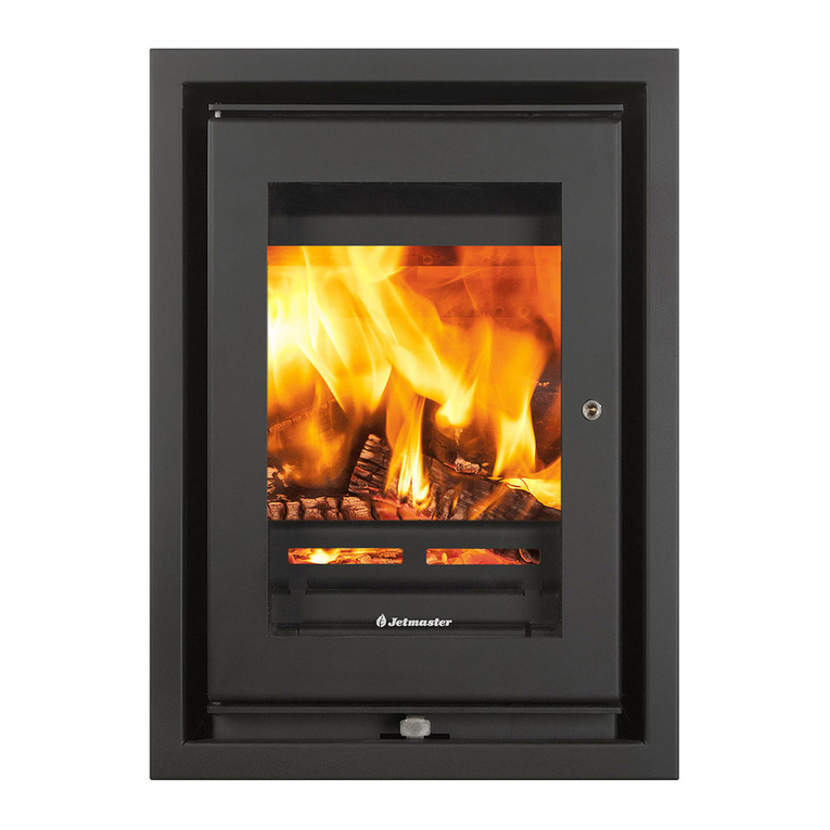
Jetmaster 18f Owner's manual

FIRES WITHOUT COMPROMISE
JETMASTER STOVE
Installation, Operating and Servicing Instructions
Please leave these instructions with the customer
SERIAL NUMBER...……………………………..
JETMASTER MK6
!!! !"!
"!
!!
!!
"(+
EXCEPTIONAL FIRES

Contents
Installer Details.................................................................................................................................................................... 4
Installation Data Table and Dimensions............................................................................................................................ 5
INSTALLATION INSTRUCTIONS
Introduction
Dimensions............................................................................................................................................................................ 6
Regulations............................................................................................................................................................................ 6
Important Points To Note Before Starting Installation............................................................................................................ 7
Paint ...................................................................................................................................................................................... 7
Installation Requirements................................................................................................................................................... 7
Unpacking.............................................................................................................................................................................. 7
Chimneys and Flues.............................................................................................................................................................. 8
Soundness of Flue................................................................................................................................................................. 8
Flue Size/Dimensions............................................................................................................................................................ 8
Use of Existing Chimneys...................................................................................................................................................... 8
Termination............................................................................................................................................................................ 9
Register Plates ...................................................................................................................................................................... 9
Bends .................................................................................................................................................................................... 9
Sweeping............................................................................................................................................................................... 9
Flue Adaptor .......................................................................................................................................................................... 9
Hearths, Fire Surrounds and Shelves ................................................................................................................................... 9
Hearths.................................................................................................................................................................................. 9
Protection of Heat................................................................................................................................................................ 10
Additional Protection of Heat............................................................................................................................................... 10
Plastering............................................................................................................................................................................. 10
Air Supply ............................................................................................................................................................................ 11
Air Supplied from Room ...................................................................................................................................................... 11
Air Supplied from External Source ...................................................................................................................................... 11
Fitting the Fire.................................................................................................................................................................... 12
Site Preparation for Fitting................................................................................................................................................... 12
Builders Opening................................................................................................................................................................. 12
Inglenook Installations or Freestanding............................................................................................................................... 12
Appliance Preparation ......................................................................................................................................................... 12
Door Removal...................................................................................................................................................................... 12
Tertiary Air Tubes................................................................................................................................................................. 13
TertiaryAirTubeRemovalandLowerBafeRemoval ........................................................................................................ 13
UpperBafeRemoval ......................................................................................................................................................... 14
Internal Board Removal (Bottom, Rear and Sides) ............................................................................................................. 15
Ash Pan Removal................................................................................................................................................................ 15
Bottom Board Grate Removal ............................................................................................................................................. 16
Rear Board Removal........................................................................................................................................................... 16
Side Board Removal............................................................................................................................................................ 16
Log Attachment ( Log Box Attachment)............................................................................................................................... 17
External Air Supply Fitting ................................................................................................................................................... 17
Flue Adaptor Connection to Fire.......................................................................................................................................... 17
RettingtheInternalComponents....................................................................................................................................... 17
Fitting the Log Retainer ....................................................................................................................................................... 18
Fitting the Ash Pan .............................................................................................................................................................. 18
Fitting the Rear Heat Shield (Optional extra)....................................................................................................................... 18
Protection of Heat................................................................................................................................................................ 19
Commissioning
After installation is complete................................................................................................................................................ 20
Door Tension Adjustment..................................................................................................................................................... 20
Air Supply ............................................................................................................................................................................ 20
Smoke Draw Test ................................................................................................................................................................ 20
TrimmingtheUpperandLowerBafes ............................................................................................................................... 21
Page

Notice Plate ......................................................................................................................................................................... 21
Carbon Monoxide (CO) Alarm ............................................................................................................................................. 21
Cleaning Up......................................................................................................................................................................... 21
Lighting After Installation ..................................................................................................................................................... 21
Chimney Sweeping.............................................................................................................................................................. 22
Handing Over ...................................................................................................................................................................... 22
USERS INSTRUCTIONS
General ............................................................................................................................................................................... 23
Warnings ............................................................................................................................................................................. 23
Safety Information............................................................................................................................................................. 23
Carbon Monoxide (CO) Alarm ............................................................................................................................................. 23
Chimney Sweeping.............................................................................................................................................................. 23
Chimney Fires ..................................................................................................................................................................... 24
HowdoIknowwhenIhaveachimneyre? ....................................................................................................................... 24
WhatshouldIdoifIhaveachimneyre?........................................................................................................................... 24
Protection of Heat................................................................................................................................................................ 25
Additional Protection of Heat............................................................................................................................................... 25
Operating Instructions
Lighting after Installation...................................................................................................................................................... 25
Operating Tool ..................................................................................................................................................................... 25
Door Operation.................................................................................................................................................................... 26
Wood Burning...................................................................................................................................................................... 26
Lighting with Wood .............................................................................................................................................................. 26
Use of the Air Supply Control .............................................................................................................................................. 26
Damping Down for Longer Periods ..................................................................................................................................... 27
Seasonal Use ...................................................................................................................................................................... 27
Fuels.................................................................................................................................................................................... 27
Recommended Fuel Types.................................................................................................................................................. 27
Wood ........................................................................................................................................................................... 27
Cleaning and Maintenance.................................................................................................................................................. 27
Glass Door........................................................................................................................................................................... 27
SERVICING INSTRUCTIONS
Servicing.............................................................................................................................................................................. 28
Chimney Sweeping.............................................................................................................................................................. 28
Seal Checks ........................................................................................................................................................................ 28
Smoke Draw Test ................................................................................................................................................................ 28
DoorRemovalandRetting ................................................................................................................................................ 28
Log Retainer Removal......................................................................................................................................................... 28
TertiaryAirTubeRemovalandLowerBafeRemovalandRetting ................................................................................... 29
UpperBafeRemovalandRetting .................................................................................................................................... 29
Internal Board Removal (Bottom, Rear and Sides) ............................................................................................................. 29
Ash Pan Removal and Replacement................................................................................................................................... 29
Bottom, Rear and Side Board Removal and Replacement ................................................................................................. 29
Door Glass Replacement and Seal Replacement............................................................................................................... 29
Servicing Door Seal between Door Frame and Stove Body................................................................................................ 30
Replacing Glass and Glass Seal to Door ............................................................................................................................ 30
Door Tension Adjustment..................................................................................................................................................... 31
Cleaning and Maintenance.................................................................................................................................................. 31
Glass Door........................................................................................................................................................................... 31
Jetmaster Guarantees
Jetmaster Provides Two Guarantees .................................................................................................................................. 32
Automatic Two Year Guarantee........................................................................................................................................... 32
Registerable Five Year Guarantee ...................................................................................................................................... 32
Terms and Conditions.......................................................................................................................................................... 32
Statutory Rights................................................................................................................................................................... 33
Complaints........................................................................................................................................................................... 33
Specications ...................................................................................................................................................................... 33
Trademark ........................................................................................................................................................................... 33

Fire Details
Serial Number
Model
Installation Date
Purchased From
Name
Address
Tel
Date
Installation By
Installer Name
Company
Address
Tel
Commissioning
Flue type correct
Flue swept and soundness checked
Smoke draw test (spillage) carried out
Air supply checked
Controls explained
HETAS Number
Signature
Print name
Please Circle One
YES NO
YES NO
YES NO
YES NO
YES NO
4
The data can be found on the data badge located at the rear of the stove

Installation Data Table
DIMENSIONS
MODEL
WIDTH
HEIGHT (Small Legs)
HEIGHT (Large Legs)
DEPTH
WEIGHT
OUTPUTS /
TEMPERATURES WOOD
ROOM SIZE HEATED
TOTAL NOMINAL HEAT
OUTPUT WOOD WHEN
TESTED TO EN13240: 2001
NET EFFICIENCY WOOD
TO EN13240: 2001
FLUE GAS TEMPERATURE
TO EN13240: 2001
FLUE GAS MASS FLOW TO
EN13240: 2001
MEAN CO2 IN FLUE GAS
TO EN13240: 2001
MEAN CO @ 13% O2 TO
EN13240: 2001
FLUE SIZE
MINIMUM FLUE SIZE
DIAMETER
MINIMUM FLUE AREA
MINIMUM FLUE DRAUGHT
CHIMNEY HEIGHT
ABOVE FIRE
AIR SUPPLY
AREA
MAXIMUM WOOD SIZE
Length & Diameter
MAXIMUM REFUEL WEIGHT
MINIMUM REFUEL
INTERVAL
mm
ins
mm
ins
mm
ins
mm
ins
Kg
M³
kW
%
°C
gs-1
%
%
mm
in
cm2
in2
Pa
M
ft
cm2
in2
mm
Kg
Min
18f
426
16 3/4
650
25 5/8
700
27 1/2
380
15
55
100
4.9
84
227
3.5
11.65
0.30
125
5
123
20
12
4.5
15
0*
0*
300 Lth
Ø75
1.28
60
60f
608
24
650
25 5/8
700
27 1/2
380
15
-
150†
7.5†
80†
-
-
-
-
150
6
177
28
12
4.5
15
14
2.5
450 Lth
Ø100
2.25†
60†
5
MODEL 18f 60f
* An air supply may be required in homes which have high levels of
air-tightness
† Jetmasterestimatedgures
426mm (608mm)
DIMENSIONS IN BOLD ARE FOR 18f DIMENSIONS IN BRACKETS ARE FOR 60f
380mm (380mm)
355mm (355mm)
15mm (15mm)
134mm (134mm)
109mm (109mm)
130mm (150mm) Internal diameter
213mm (304mm) 10mm
(10mm)
45mm
(45mm)
500mm
(540mm)
105mm
(105mm)
SHORT LEG SHOWN 105mm (105mm)
LONG LEG NOT SHOWN 155mm (155mm)
DOOR LOCK
FLUE SPIGOT
AIR CONTROL LEVER AIR SUPPLY PIPE
63mm (63mm)
HEAT SHIELD

Installation Instructions
Introduction
READ THESE INSTRUCTIONS CAREFULLY BEFORE STARTING THE INSTALLATION. CLOSE ATTENTION
TO THE DETAILS OF INSTALLATION WILL ENABLE YOU TO GET THE BEST RESULTS FROM YOUR
FIRE.
NOTE: THESE INSTRUCTIONS SHOULD BE RETAINED FOR FUTURE REFERENCE.
Dimensions
The installation data table contains all the dimensional information necessary to allow the installation to be
properly planned.
Regulations
In the United Kingdom the installation must be in accordance with:-
●The Building Regulations issued by the Department of the Environment or the Building Standards (Scotland)
(Consolidation) Regulations issued by the Scottish Development Department.
●All relevant codes of practice and relevant parts of any local regulations, including those referring to National
and European standards.
●In your own interest and for safety, in the United Kingdom, it is the law that all solid fuel appliances are
installedbycompetentpersons,aregisteredinstallerorapprovedbyyourlocalbuildingcontrolofcer.The
Heating Equipment Testing and Approval Scheme (HETAS) require its members to work to recognised
standards.
●In other countries the installation must also conform to the national and local regulations in force. This may
include only the use of permitted fuels in some countries.
THIS APPLIANCE IS DESIGNED AND APPROVED TO BURN WOOD WITH THE DOOR CLOSED.
THIS APPLIANCE IS NOT DESIGNED TO BURN GAS.
THIS APPLIANCE IS NOT DESIGNED TO BE FITTED INTO BOATS.
A. The chimney must be swept and of correct dimensions, be suitable for use with a wood burning stove and
be terminated clear of any possible wind effects.
B. There must be an adequate supply of air into either the appliance if an external air supply is used, or
adequate air supply into the room if an external air supply is not used.
6

Important Points to Note before Starting Installation.
Paint
Itisstronglyrecommendedthatthereisprotectedfromcementandplastersplashesduringinstallation,as
thesearedifculttoremovefromthesurfaces.
Installation Requirements
Thesurfaceofthehearthandreplaceoormustbesufcientlyattoensurethatthestovecanstandlevel.Any
excessiveunevenness(uneventiles,stone,etc.)shouldberectied.Thereareadjustablefeetateachcorner
of the stove to take up any small deviations in level.
The appliance must not stand on combustible materials or carpets.
Unpacking
Takecarewhenunpackingtheretoavoidaccidentaldamage.Particularcareshouldbetakenwiththeglass
door and the air control mechanism.
Ensure that all the listed items are present before commencing installation.
●Stove Body
●Board Set
●Log Retainer
●Legs x 4
●Leg Bolts x 4
●Door operating tool
●Installation & Operating Instructions
●Guarantee card
Not supplied as standard:
●Log Box ●Heat Shield
●Long Leg Option
Leg Length 155mm
7
●Optional external air kit
consisting of:
1. Flexible air pipe
2. Adaptor Sleeve
3. Clamp

Chimneys and Flues
Theueandchimneymustbeinspectedbeforeinstallationtoensurethatitissuitablefortheappliancebeing
tted.ChimneyanduesystemsmustmeettherequirementsoftheBuildingRegulationsDocumentJ.
Soundness of Flue
Theuemustbesoundandfreefromcracksandobstructions.Newuesshouldbelined.
All ues should be swept clean prior to installation and inspected for soundness and freedom from
blockages.
Anyuelinermustcomplywiththetestrequirementsforuelinersforusewithburningsolidmineralfuels.
Flue Size / Dimensions
Weatherthechimneyisoldorisnewlybuilt,itsdimensionsmustbeadequatetosupportthesizeofretobe
installed.Thelargerthere,thegreaterthesizeofueandthetallerthechimneyrequired.Whenspecifyingue
liners, ensure that the important internal dimensions are stated.
Theminimumheightofanyuemustbe4.5mmeasuredfromthetopoftheretothetopoftheue.Seethe
installationdatatableforrecommendeduesizeandminimumchimneyheight.
Fluelinersoruepipeusedmustbeofthecorrectsizeforthereandmustbesuitableforusewithsolidfuel
res.Fluepipesofaluminiumorasbestosmaynotbeused,normayexiblepipesofaluminiumorsinglewall
stainless steel.
Theuemustnotbeusedforanyotherapplianceorapplication.
Use of Existing Chimneys
Thesemustbesweptandinspectedfordimensionsandsoundnessbeforestartingtoinstallthere.Existingue
linersshouldbeinspectedandreplacedifrequired.Iftheuehaspreviouslybeenusedwithanopenrethen
itshouldbesweptaftertherstmonthofusingitwiththestovetted.Thiswillclearanyloosesootdeposits
fromprevious“open”reburning.
8
STOVE BODY
(Inner Boards not shown)
BOARD SET
STANDARD LEG, BOLT
AND FOOT SUPPLIED
Leg Length 105mm
DOOR
OPERATING
TOOL
LOG
RETAINER

Termination
It is important to terminate the top of the ue in such a way that it will allow free passage of combustion
products to the atmosphere without being subjected to turbulent air or high pressure zones that could cause a
downdraught.
Building regulations stipulate minimum clearance above windows and ventilation openings.
Potsshouldbesimple,opentoppedandwiththesameinternaldiameterastheue.Unconventionalpotsor
terminals must be so designed that will operate satisfactorily in all wind directions. Take steps to prevent birds
nesting in the terminal. Thatch roofs need specialist advice. Please contact your chimney supplier.
Register Plates
Where a register plate is required it must conform to the building regulations..
Bends
Theidealueisstraightandvertical.Newchimneysmustnotdeviatemorethan45ºfromthevertical,butitis
desirablethatthedeviationsdonotexceed30º.Bendsgreaterthan30ºshouldbeavoidedwherepossible.In
olderchimneysbendsexceeding45ºmaybefoundandwilldegradeueperformance.
Sweeping
Thechimneycanbesweptthroughthere.Thereisprovidedwithremovablebafeboardstofacilitatechimney
sweepingandfortheremovalofsootfromtheunit.Theremustbeinstalledinsuchawaythatthiscanbe
carriedout.Accesspanelsmayalsobeprovidedintheuetofacilitatecleaning.Collectionofanydebrismust
be easily removable.
Flue Adaptor
TheJetmasterstoveisnotastructuralunit;althoughveryrobustitisnotdesignedtotaketheweightoftheue.
Therefore a structural lintel will need to be provided for clay liners or in the case of pre fabricated stainless steel
chimneythechimneymanufacturesrecommendedxingbracketsormethodmustbeused.
Hearths, Fire Surrounds and Shelves
Theoororrecessonwhichtherestandsshallhaveadequateloadbearingcapacity.Particularattentionshall
be paid to existing constructions.
Itisimportanttoensurethatthereplaceisinstalledonanoncombustiblesurface.
Donotinstallthisunitdirectlyontowoodenorcarpetoors.
Anyresurroundorhearthshouldbesuitableforusewithasolidfuelre.
Allowancesmustbemadeforexpansionandcontractionwhenttingmaterialsupagainsttherewhichmay
become hot.
9
Hearths
Newhearths,replacesrecessesandchimneysshouldbeconstructed
in line to conform to Building Regulations Document J.
The hearth must be made from non combustible material and at least
12mm thick.
The hearth must protrude at least 225mm forward from the front face
of the appliance and 150mm each side from the edge of the appliance.
See diagram.
It must be structurally sound to withstand the weight of the appliance
with it’s fuel load.

Hearths,orplinthsconstructedtosupportthereabovethehearth,mustbehorizontal.
Anyholeinthewallinstallationwillstillrequireahearthtobetted.
Protection of Heat
Aheatshieldisavailableasanoptionalextra.Tottheheatshieldseesectionon“ttingtherearheatshield”.
Thedistancetocombustiblematerialwillbereducedwhentheheatshieldistted.
Rear Rear Heat
Model No Heat Shield Shield Fitted
Sides Back Sides Back
18f 600mm 800mm 600mm 250mm
60f - - - -
Additional Protection of Heat
Asonallheatproducingappliancestheuseofammablewallcoveringsdirectlyaboveortothesidesofthe
remaylead to arehazard.Please bear thisinmindwhen installing theapplianceordecorating. Dueto
theextremetemperaturesthatcanbeachievedabovetherealwaysensurethatanyTV’s,paintingsorother
combustible items that may be near do not become excessively hot. For TV’s always consult the manufacturers
instructions to see if exposure to heat will cause damage.
Plastering
Hotaircancausestainingabovethereinthesamemannerasonthewallabovearadiator.
Thisoftenshowsmoreonlightercolourednishedsurfaces.
Theareadirectlyabovetherewillbecomeveryhot.Thereforetoreducetheriskofcrackingweadvisethe
following:
Whenplasteringabovethere,treinforcingmesh(expandedmetallathing)foratleast225mmabovethere
andforthefullwidthofthere.Thismeshcanbecontinueddownthesidesofthere.
Use a high temperature or other heat resistant plaster.
10
Combustible Wall
Heat Shield
250mmwithHeatShieldtted
Stove

11
Air Supply
Allresrequireasupplyofairtosupportcombustionandtoallowthechimneytodrawcorrectly.
Airstarvationwillresultinpooruedrawandsmokinessintheroom.
All installations will require a permanent dedicatedairsupplyforthereofatleast5.5cm2perkWofratedheat
outputover5kW.Thesizeofairsupplyductorductsrecommendedforeachreisshownintheinstallation
data table.
Anairsupplymayberequiredinhomeswhichhavehighlevelsofairtightnessevenifthereoutputis5kWor
less.
The Building Regulations Document J and L must be taken into account when providing ventilation for
there.
Newly constructed houses, especially those using double-glazing and employing modern draught control
techniques, will need careful planning of air entry.
Extractorsorfanswhenoperatedinthesameroomoradjoiningroomoftheremaycauseproblems.
If there is a fan or extractor tted in the property then allowance for additional air may be required. See
commissioning section.
If there is more than one appliance in the property then each appliance must be supplied with adequate
combustion air and ventilation so that all the appliances can operate simultaneously.
Air Supplied from Room
Bringairintotheroomclosetothere.Theidealpositionisjusttothesidesofthereplaceopeningasshown.
Itcanbesplitandbroughtupintwopositionsifrequired,oneeachsideofthereplaceopening.
Careful positioning of the vents is essential so that they are not liable to become blocked and cause cold
draughts.
Wherepossible,drawairfromtwowallsatrightanglesandducttoamixingchamberbeneaththeoorbefore
itenterstheroom.Thiswillreducetheinuenceofstrongwindsonthesupplyofair.Whereanexistingoor
is solid, vents may have to be provided through the walls in a manner, which achieves conditions as close as
possible to the above, perhaps, by the use of ducting or of false skirting.
Wherethereisasuspendedooroverawellventilatedunderoorspace,itmaybesufcientjusttosetventilation
openingsthroughtheoorboardsadjacenttothechimneybreast.Olderhouseswiththepossibilityofdraughts
enteringarounddoorsandwindowswillstillprotfromtheprovisionofaseparateairsupplyas,properlyplaced,
this will stop or reduce cold draughts.
DONOTsetaventilationgrilleinthehearthimmediatelyinfrontofthere.Thecoldairenteringtheroomwill
formacold‘curtain’infrontofthereandmaydestroythewarmairaroundtheroom.
DONOTplaceanairsupplyinletacrosstheroomfromthere.Thedraughtofcoldaircrossingtheroomwill
scourtheroomofwarmairandtheoverallheatingeffectoftherewillbereduced.
DO NOT set a ventilation grille in a position where they may become liable to blockage.
Wheretheoorissolid,ventsneedtobeprovidedthroughthewallsinamanner,whichachievesconditionsas
close as possible to the above, perhaps, by use of ducting or false skirting.
When bringing in the air supply consideration should be given to any regulations that would effect the position of
any ducting or ventilation grilles.
Air Supplied from External Source
The primary air can be taken from an external source from outside
the building.
Thereisaexiblesleevethatslidesovertheairinletpipeattached
to the rear of the stove. An air kit is available as an optional extra
to do this.
With this in place the exible pipe can be fed through the wall
oroortoanexternalairsource.Anopengrillemaybeattached
to the end of the exible pipe to stop debris from blocking the
pipe. Ensure that the grille does not restrict the air supply. The air
requirements are listed in the installation data table.

Externalairsupplypipetted
Fitting the Fire
Site Preparation for Fitting
Builders Opening
If installing the re in an existing replace, rst remove all loose material from the recess and measure the
openingandrecesstoensurethattheJetmasterstove,whentted,satisestheclearancespeciedinPartJof
The Building Regulations. The recess must be large enough to provide a clearance around the sides and back
thatconrmswiththeregulations.Theoptionalextraheatshieldmayneedtobetted.Allowextraheightif
connectingdirectlytotheexistinguetomaketheconnection.
Donotremoveanystructurallintelswithoutrstseekingexpertadvice.Oftenidenticationandlocationofthe
lintel can be found by removing some surface plaster above the opening that is to be altered.
For details of stove sizes see installation data table.
Theremustbedirectlyconnectedtotheuesystem.Withanexistinguecheckthatasealedueconnection
canbeachievedbetweenthereadaptorandtheue.
Inglenook Installations or freestanding
Fluelinersoruepipeusedmustbeofthecorrectsizeforthereandmustbesuitableforusewithsolidfuel
res.Fluepipesofaluminiumorasbestosmaynotbeused,normayexiblepipesofaluminiumorsinglewall
stainless steel.
Appliance Preparation
Door Removal
Unlock the door with the handle provided.
Open the door fully and carefully support the door, at the same time pull down the spring loaded pin at the top
ofthedoorandliftthedoorupandoutwardsawayfromthelowerhingeattachmentsontherebox.Setaside
inasafeplaceforrettinglater.
12

Releasing the door pin
Take care not to damage the door seal.
Place the door on a soft surface in a safe position to protect the glass, paint and inner seal.
Particular attention should be given so that the painted edges do not become damaged.
Retthedoorusingthereverseprocess.
Lower door pin on stove body Upper door pin attached to door
Tertiary Air Tubes
Therearetwotertiaryairtubeslocatedattheinnertopofthestovetobringairintothere.Oneislargeandone
is small. Each tube is held in its position by a swing cam catch attached with a single 8mm bolt to the left hand
innersideoftherebox.Thecamcatchhasalocatoratitsendthatlocatesinaholeattheendofthetube.When
the cam catch locator is positioned in the tube hole the bolt is tightened to hold it in this position thus trapping
the tube. This ensures that the tube will not slide out and it keeps the tube with its tertiary air ports in the correct
position within the stove.
Abovethetwotubesare2setsofbafeboards.Thetwolowerbafesareloose,justrestingonthetubesand
touchingtherearofthestove.Theyarenotxedwithanyxings.Theoneupperbafeisheldinplacebya
bracket at the rear and a bracket at the front top, being trapped between the two brackets.
Upperbafeboardandlocationbrackets
TertiaryAirTubeRemovalandLowerBafeRemoval
Thesequenceforeasyremovaloftheairtubesandlowerbafesarethus:
Firstremovethefronttertiaryairtubeclosesttothedoorofthere.
To remove the tube, slacken the 8mm bolt using the 13mm spanner provided. Once the bolt is slack then the
cam catch can be rotated slightly so that the locator comes away from the tube hole releasing the tube.
13

There is no need to remove the 8mm bolt completely. It is easier for reassembly to just leave it loose.
8mm bolt holding cam latch Cam latch
Once this has been carried out then the tube can be slid across so that one end is released from the side
chamber to drop down allowing space to pull it out of the other side of the chamber.
Nextslideforwardthelowerbafesoverthereartubeanddroptheirfrontedgedownandremovethemfromthe
re.Notetheirorientationastheyarelongeralongoneedge.
Finally remove the rear tube in the same manner as the front tube.
Replacement is the reverse procedure.
FirstttheRearTube,thenthelowerbafesandthentheFrontTube.
CAUTION
Ensure that the cam catch locator is positioned in the tube hole when the bolt is tightened to trap the tube from
slidingoutandtoensurethatthetertiaryairportsareintheircorrectpositionwithinthere.
Ensurethatthebafesarettedthecorrectwayaround.
14
Rear tertiary air tube
Front and back tertiary tubes are
designed to slide across to be
released from side chambers
Front tertiary air tube
Cam Catch
Cam Catch
Cam Catch
8mm bolt
UpperBafeRemoval
Abovethelowerbafesisanupperbafe.Toremovethis,rstremovethetertiaryairtubesandthelowerbafes.
Oncethishasbeencarriedoutthentheupperbafecanberemoved.
Theupperbafeisheldinplacebetweenarecessedbracketinthebackpanelandabracketatthetopfrontthat
supportsit.Thebackoftheupperboardtsinarecessattherearofthestove.Thustheboardistrapped/rests
between the front bracket and the rear of the box.

Upperbafeboardandlocationbrackets
Toremovetheupperbafepulltheboardforwardoutoftherearrecessandlowertheboarddown.
This is achieved by lifting the front of the board up and at the same time pulling forward so that the rear of the
board “tongue” disengages from the recess bracket in the back panel. Then drop the rear of the board down,
lowering the front to clear the fornt bracket.
Note:Notoolsarenecessarytoremovetheupperbafe.
Internal Board Removal (Bottom, Rear and Sides)
The internal boards need to be taken out in the following sequence:-
IMPORTANT First remove the ashpan, then the base board, rear board and side boards.
Although the boards are durable care should be taken not to break them during handling.
The position of the boards must be noted so that they can be replaced back in the same positions and order.
Notealsothatsomeoftheboardscanonlybettedonewayaroundorarehanded.
Board set - bottom, rear & sides
Ash Pan Removal
Remove the ashpan as shown.
15

Bottom Board Grate Removal
The bottom board can be removed by lifting up at the rear edge. There is a small recess at the centre, along the
rear edge that will assist in lifting the board at the back edge. Then gently slide the board rearwards releasing
thefrontoftheboardfromunderthefrontmetalange.Thebottomboardwillneedtiltingsidewaystoclear
the stove opening when removing. Care should be taken to ensure that the board does not become damaged.
Lifting the board can be helped by pushing up the board from the ash pan recess with one hand and lifting the
rear of the board at the recess.
Recess in rear of board
Bottom board can be lifted by pushing Tilt board to remove
up from under the ashpan recess
Rear Board Removal
Removetherearverticalboardbygentlypullingthetopedgeoutrst,thenslideforward.
The rear board will need to be tilted/twisted sideways to clear the stove opening in a similar manner to the bottom
board.
Side Board Removal
Theleftandrightsideboardscanberemovedbygentlypullingoneedgeoutrstthen,slidetheboardstowards
the centre of the stove.
16

Toreplacetheboardsofferoneedgeinrstandthenpushtheboardgentlyback.
Note:Theyshouldbepushedbackatagainstthesteelbodyofthere.
Note:Someoftheboardswillonlytonewayaroundandiftheyareforcedwillbreak.
Leg Attachment (Taller legs and log box available as optional extra)
Withallthecomponentsremovedfromtheinsideoftherebodythestovecannowbelayedonit’sbackand
the legs attached to the underside with the bolts provided.
The standard leg supplied is 105mm high. An option of the taller leg (155mm) or log box is available as an
optional extra which are held in place using the same bolts.
External Air Supply Fitting
The primary air can be taken from the room or alternatively it can come from an external source from outside
the building.
Iftakenfromtheroomthenairductsarerequiredtotheroom,astherewilltakeitsprimaryairfromtheroom.
See section on Air supply for details.
Ifairisrequiredtobebroughtinfromanexternalsourcethenaexiblepipecanbepushedovertheairchamber
pipe attached to the rear of the stove.
Theexiblepipeshouldbeheldinplacewiththecircularclampsupplied.
Itisusuallyeasiertottheexiblepipetothestoverstthenslidetheexiblepipethroughanyholesinthewall
oroortoanexternalairsource.Anopengrillemaybeattachedtotheendoftheexiblepipetostopdebris
from blocking the pipe. Ensure that the grille does not restrict the air supply. The air requirements are listed in
the installation data table.
Flue Adaptor Connection to Fire
Oncethestoveislocatedinsituthentheuepipecanbejoinedtothestove.
Atightandeffectivesealmustbemadebetweenthestoveandtheue. It is essential that the system be
sealedateachjointsothattheonlyair,whichcanreachtheue,isthatwhichentersthroughthestove.Iftheue
ofthestoveisnotsealed,aircouldleakintotheueandchimneyperformancewillbeimpaired.Alternatively
products of combustion could enter the room causing a serious health risk.
RettingtheInternalComponents
Oncetherehasbeenttedthenreplacementoftheinternalpartscanbenished.
Rettherecomponentsbyreversingthesequenceofstepsaboveintheremovalsection.
Sideboards,rearboard,bottomboard,upperboardbafe,reartube,lowerboardbafes,fronttubeandnally
the door.
Check the door seals correctly.
Check the operation of the air control.
17

Fitting the Log Retainer
The log retainer is attached at the front of the stove by sliding down between the slots at each side at the front.
Theretainershouldbettedthecorrectwayaroundasshowninthediagram.
Fitting the Ash Pan
Fittheashpanbyslidinginunderthebottomgrateboard.Ensureitisttedthecorrectwayaroundwiththe
handle towards the front as shown below.
Fitting the rear Heat Shield (Optional Extra)
Therearheatshieldisttedtotherearofthestovebyclippingtheslotsoverthereboxboltslocatedeachside
at the top and bottom of the rear of the stove.
Heat Shield Locating Slot
Top Bolt Bottom Bolt
18

Lifttheshieldhigherthanthestove,pushtowardsthestoveandthenpushdownlocatingtheslotovertherebox
bolts. If the shield cannot be engaged then adjust the bolts by unscrewing outwards or screwing inwards slightly
soastheshieldtscorrectly.Finallytightentheboltstoxtheheatshieldtothestovebody.
Ensure that the shield is not pressed tight against any combustible surface. Ensure correct distance away from
rear of combustible material as shown.
Protection of Heat
Aheatshieldisavailableasanoptionalextra.Tottheheatshieldseesectionon“ttingtherearheatshield”.
Thedistancetocombustiblematerialwillbereducedwhentheheatshieldistted.
Rear Rear Heat
Model No Heat Shield Shield Fitted
Sides Back Sides Back
18f 600mm 800mm 600mm 250mm
60f - - - -
19
Combustible Wall
Heat Shield
Stove
250mmwithHeatShieldtted

Commissioning
After Installation Is Complete
In your own interest and for safety, in the United Kingdom, it is the law that all solid fuel appliances are
installed by competent persons, a registered installer or approved by your local building control ofcer. The
Heating Equipment Testing and Approval Scheme (HETAS) require its members to work to recognised
standards.
Door Tension Adjustment
The door tension latch is factory set to give the optimum pressure on the door seal. It should not normally need
any adjustment until after the stove has had some considerable use or has had the glass replaced. However,
after installation and before commissioning adjust the door latch tension if required. The latch tension is adjusted
by adding or removing the shim washers behind the outer door latch.
This will adjust the tension of the door seal against the stove body.
Air Supply
Whencommissioningthereensurethattheairsupplyisadequateforthere.Anairsupplymayberequiredin
homeswhichhavehighlevelsofairtightnessevenifthereoutputis5kWorless.Particularattentionshouldbe
observed if there is a ceiling fan or extractor fan in the room or adjoining room as this may have an effect on the
drawoftheue/re.Thereshouldbetestedwiththeceilingorextractorfanonandwithallinterconnecting
doors to the room closed and then open. If required additional air may be required to overcome the extractor or
fan pressure.
Smoke Draw Test.
Ensure appliance is not alight.
Warm chimney for 10 minutes using a blowlamp or similar heating device.
Placeasmokepelletinthewoodtrayorbasketgratetowardsthefrontoftheopeningofthereandignitethe
pellet.
Open the air control valve and close the door.
Checkthatthesmokeisbeingdrawnuptheueandthatitisdischargingsatisfactoryattheueterminal.
Ifthetestfailsthentheueandairsupplyshouldbechecked.Ifthiscannotberesolvedthenfurtherinvestigation
will be required or seek expert advice.
Lightthereasdetailedinthelightinginstructionsandallowtheappliancetoheatuptoitsoperatingtemperature
checking that no spillage occurs. There may be some fumes due to the burning off of protective oils and paint
curing. This should not be confused with spillage.
When the operating temperature has been reached, open the door slowly and carry out a spillage test with a
smokematch around thedoor opening. If excessivespillage occursthen the ueand airsupply should be
checked. If after further re-testing this cannot be resolved then further investigation will be required or seek
expertadvice.Advisethecustomernottousethereuntilexpertadvicehasbeensought.
20
This manual suits for next models
1
Table of contents
Other Jetmaster Stove manuals
Popular Stove manuals by other brands

Sunjoy
Sunjoy A301002000 Assembly instructions

Plamen
Plamen Alberto Installation and operating instructions

Ecoflam
Ecoflam Ares 7,4 kW EKO Installation & operation instructions

Olsberg
Olsberg Alegre Compact Instruction

Stanley
Stanley K50 Installation and operating instructions

Henley Stoves
Henley Stoves THE ACHILL user manual

Relags
Relags Origin Outdoors MINI manual

Harman Stove Company
Harman Stove Company 44 Magnum Installation & operating manual

Harrie Leenders
Harrie Leenders PHAROS INTERIOR Instructions for installation, use and maintenance

Harman
Harman Absolute 43 owner's manual

Stuv
Stuv 16-cube Series installation manual

Mustang
Mustang 615967 quick start guide