Jetmaster INSET STOVE MKIII 16i Owner's manual

JETMASTER INSET STOVE MK2
16i, 18i, 50i, 60i, 70i, 60i Low, 70i Low
Installation, Operating and Servicing Instructions
Please leave these instructions with the customer
SERIAL NUMBER...……………………………..

CONTENTS
TECHNICAL SPECIFICATIONS .................................................................................................................................................................5
INSTALLATION INSTRUCTIONS
Introduction................................................................................................................................................................................................6
Dimensions..................................................................................................................................................................................................6
Regulations..................................................................................................................................................................................................6
Health and Safety Precautions....................................................................................................................................................................6
Important Points to Note before Starting Installation...................................................................................................................................7
Convection Inlet...........................................................................................................................................................................................7
Paint ............................................................................................................................................................................................................7
Modular Construction ..................................................................................................................................................................................7
Fire Cement.................................................................................................................................................................................................7
Asbestos......................................................................................................................................................................................................7
Metal Parts ..................................................................................................................................................................................................7
Installation Requirements.........................................................................................................................................................................7
Unpacking....................................................................................................................................................................................................7
Chimneys and Flues....................................................................................................................................................................................8
Soundness of Flue.......................................................................................................................................................................................8
Flue Size / Dimensions................................................................................................................................................................................9
Use of Existing Chimneys............................................................................................................................................................................9
Termination..................................................................................................................................................................................................9
Flue Outlet...................................................................................................................................................................................................9
Bends ..........................................................................................................................................................................................................9
Sweeping.....................................................................................................................................................................................................9
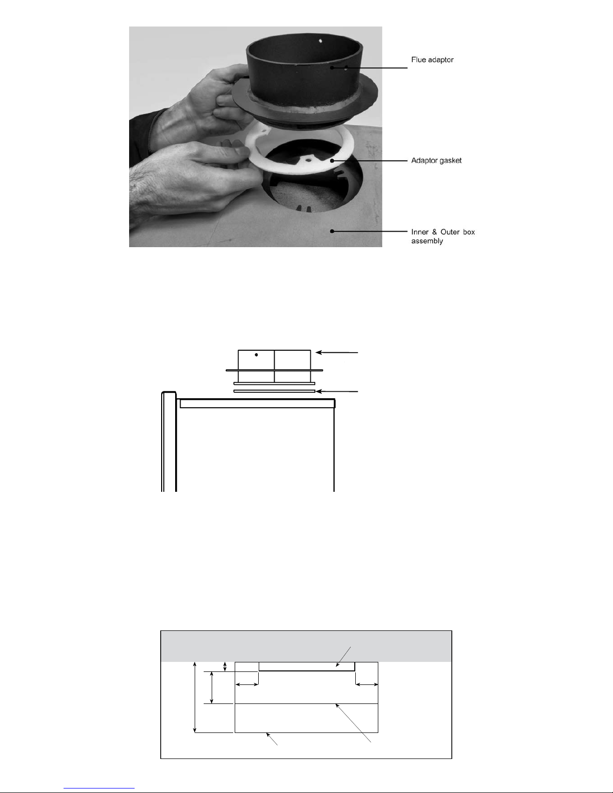
Flue Adaptor with Liner................................................................................................................................................................................9
Flue Adaptor with Existing Flue .................................................................................................................................................................10
HEARTHS .................................................................................................................................................................................................10
COMBUSTIBLE MATERIALS....................................................................................................................................................................11
Protection of Heat......................................................................................................................................................................................11
Fire Surrounds and Shelves......................................................................................................................................................................11
Pictures and TV’s ......................................................................................................................................................................................11
Plastering...................................................................................................................................................................................................11
Air Supply ..................................................................................................................................................................................................12
Air Supplied from Room ............................................................................................................................................................................12
Air Supplied from External Source ............................................................................................................................................................13
Fitting the Fire..........................................................................................................................................................................................13
Site Preparation for Fitting.........................................................................................................................................................................13
Builders Opening.......................................................................................................................................................................................13
Inglenook Installations or freestanding......................................................................................................................................................14
Appliance Preparation ...............................................................................................................................................................................14
Door Removal/Replacement .....................................................................................................................................................................14
Log Retainer Removal and Replacement..................................................................................................................................................15
Tertiary Air Tubes.......................................................................................................................................................................................15
BafeBoards.............................................................................................................................................................................................16
TertiaryAirTubeandLowerBafeRemovalandReplacement ................................................................................................................16
UpperBafeRemovalandReplacement ..................................................................................................................................................17
Removing and Replacing Ash Pan............................................................................................................................................................18
Bottom Grate Removal and Replacement.................................................................................................................................................18
Internal Board Removal and Replacement (Rear and Sides) ...................................................................................................................18
Rear Board Removal and Replacement....................................................................................................................................................19
Side Board Removal and Replacement ....................................................................................................................................................19
FlueAdaptorRemoval(Ifttedtore).......................................................................................................................................................19
Inner Firebox “Engine” Removal................................................................................................................................................................19
Fitting the Firebox......................................................................................................................................................................................20
Flue Adaptor Connection to Flexi Flue ......................................................................................................................................................20
Flue Adaptor Connection to Rigid Flue......................................................................................................................................................20
Outer Firebox Fitting..................................................................................................................................................................................20
InllingabovetheOuterBox .....................................................................................................................................................................21
Fitting Hot Air Ducts (Optional Extra).........................................................................................................................................................21
External Air Supply Fitting .........................................................................................................................................................................21
Inner Firebox “Engine” Fitting....................................................................................................................................................................22
Flue Adaptor Connection to Fire................................................................................................................................................................22
RettingtheInternalComponents.............................................................................................................................................................23
Fitting the Basket Grate (Optional Extra 60i and 70i)................................................................................................................................24
Fitting the Frame .......................................................................................................................................................................................24
Commissioning........................................................................................................................................................................................25
After Installation Is Complete.....................................................................................................................................................................25
Door Tension Adjustment...........................................................................................................................................................................25
Air Supply ..................................................................................................................................................................................................25
Smoke Draw Test. .....................................................................................................................................................................................25

TrimmingtheUpperandLowerBafes .....................................................................................................................................................26
Notice Plate ...............................................................................................................................................................................................26
Carbon Monoxide (CO) Alarm ...................................................................................................................................................................26
Cleaning Up...............................................................................................................................................................................................26
Lighting after installation............................................................................................................................................................................26
Chimney Sweeping....................................................................................................................................................................................26
Handing Over ............................................................................................................................................................................................27
Data Plate..................................................................................................................................................................................................27
USERS INSTRUCTIONS
General......................................................................................................................................................................................................28
Health and Safety Precautions..................................................................................................................................................................28
Safety Information...................................................................................................................................................................................29
Carbon Monoxide (CO) Alarm ...................................................................................................................................................................29
Extractor Fans ...........................................................................................................................................................................................29
Metal Parts ................................................................................................................................................................................................29
Chimney Sweeping....................................................................................................................................................................................29
Chimney Fires ...........................................................................................................................................................................................29
How Do I Know When I Have A Chimney Fire?.........................................................................................................................................29
What Should I Do If I Have A Chimney Fire?.............................................................................................................................................29
Carbon Monoxide Alarm............................................................................................................................................................................30
COMBUSTIBLE MATERIALS....................................................................................................................................................................30
Protection of Heat......................................................................................................................................................................................30
Fire Surrounds and Shelves......................................................................................................................................................................31
Pictures and TV’s ......................................................................................................................................................................................31
Operating Instructions............................................................................................................................................................................32
Lighting after Installation............................................................................................................................................................................32
Operating Tool ...........................................................................................................................................................................................32
Door Operation..........................................................................................................................................................................................32
Wood Burning and Basket Grates.............................................................................................................................................................32
Wood Burning............................................................................................................................................................................................32
Lighting with Wood ....................................................................................................................................................................................32
Operation with door left open ....................................................................................................................................................................32
Refuelling with Wood.................................................................................................................................................................................33
Refuellingontoalowrebed ...................................................................................................................................................................33
Basket Grates............................................................................................................................................................................................33
Lighting with Basket Grate.........................................................................................................................................................................33
Use of the Air Supply Control ....................................................................................................................................................................33
Seasonal Use ............................................................................................................................................................................................34
Fuels..........................................................................................................................................................................................................34
Fuel Overloading .......................................................................................................................................................................................34
Recommended Fuel Types........................................................................................................................................................................34
Cleaning and Maintenance........................................................................................................................................................................35
SERVICING INSTRUCTIONS
Servicing....................................................................................................................................................................................................36
Carbon Monoxide (CO) Alarm ...................................................................................................................................................................36
Extractor Fans ...........................................................................................................................................................................................36
Metal Parts ................................................................................................................................................................................................36
Chimney Sweeping....................................................................................................................................................................................36
Seal Checks ..............................................................................................................................................................................................36
Smoke Draw Test ......................................................................................................................................................................................37
Removing the Door....................................................................................................................................................................................37
Removing the Log Retainer.......................................................................................................................................................................37
TertiaryAirTube,LowerandUpperBafeBoardCleaning.......................................................................................................................37
Bottom Grate Removal..............................................................................................................................................................................37
Internal Board Removal.............................................................................................................................................................................37
Door Glass Replacement and Seal Replacement.....................................................................................................................................37
Servicing Door Seal between Door Frame and Stove Body......................................................................................................................38
Replacing Glass and Glass Seal to Door ..................................................................................................................................................38
Door Tension Adjustment...........................................................................................................................................................................39
Cleaning and Maintenance........................................................................................................................................................................39
Glass Door.................................................................................................................................................................................................39
Spare Parts available ................................................................................................................................................................................39
Jetmaster Stove Guarantees..................................................................................................................................................................40
Automatic Two Year Guarantee on all products ........................................................................................................................................40
Five Year Guarantee (Registerable)..........................................................................................................................................................40
Terms and Conditions................................................................................................................................................................................40
Statutory Rights.........................................................................................................................................................................................41
Complaints.................................................................................................................................................................................................41
Specications ............................................................................................................................................................................................41
Trademark .................................................................................................................................................................................................41

Fire Details
Serial Number
Model
Installation Date
Purchased From
Name
Address
Tel
Date
Installation By
Installer Name
Company
Address
Tel
Commissioning
Flue type correct
Flue swept and soundness checked
Smoke draw test (spillage) carried out
Air supply checked
Controls explained
HETAS Number
Signature
Print name
Please Circle One
YES NO
YES NO
YES NO
YES NO
YES NO
4
Thedatacanbefoundonthedatabadgelocatedattheleftsideoftheinnerrebox

5
16i 18i 50i 60i 70i 60i Low 70i Low
OPENING REQUIRED
Width 407 457 547 647 747 647 747 mm
Height 554 554 593 593 593 493 493 mm
Depth 355 355 355 355 355 355 355 mm
Width 16 18 211
/
2251
/
2 291
/
2 251
/
2 291
/
2 in
Height 217
/
8 217
/
8 231
/
8 233
/
8 233
/
8 193
/
8 193
/
8 in
Depth 14 14 14 14 14 14 14 in
FRAME/TRIM
Width A438 488 570 670 770 670 770 mm
Height B571 571 610 610 610 510 510 mm
Depth C30 30 30 30 30 30 30 mm
Width A171
/
4 191
/
4 221
/
2 263
/
8 301
/
4 263
/
8 301
/
4 in
Height B 221
/
2 221
/
2 24 24 24 201
/
8201
/
8 in
Depth C13
/
16 13
/
16 13
/
16 13
/
16 13
/
16 13
/
16 13
/
16 in
OUTER FIREBOX
Width D399 449 531 631 731 631 731 mm
Height E549 549 588 588 588 488 488 mm
Depth F347 347 347 347 347 347 347 mm
Width D153
/
4 173
/
4 207
/
8 247
/
8 287
/
8 247
/
8 287
/
8 in
Height E 215
/
8 215
/
8 231
/
8 231
/
8231
/
8191
/
4191
/
4 in
Depth F133
/
4 133
/
4 133
/
4 133
/
4 133
/
4 133
/
4 133
/
4 in
OUTPUTS (WOOD)
Room size heated 70 100 130 150 200 130 170 M3
Total nominal heat output†3.6 4.9 6.5 7.5 10 6.5 8.5 kW
Net efficiency†86 85 84 84 77 78 73 %
MINIMUM FLUE SIZE
Diameter 125 125 125 150 150 150 150 mm
Diameter 5 5 5 6 6 6 6 in
Area 123 123 123 177 177 177 177 cm2
Area 20 20 20 28 28 28 28 in2
Minimum flue draught 12 12 12 12 12 12 12 Pa
Depth to flue G150 150 150 136.5 136.5 136.5 136.5 mm
Depth to flue G6 6 6 53
/
85
3
/
85
3
/
85
3
/
8in
Flue gas temp to EN13229:2001 182 225 ✗292 350 ✗✗°C
Flue gas mass flow to EN13229:2001 2.7 3.1 ✗4.2 6.7 ✗✗gs-1
Mean CO2in flue gas to EN13229:2001 10.72 12.44 ✗14.48 12.40 ✗✗%
Mean CO @ 13% O2to EN13229:2001 0.37 0.35 ✗0.24 0.45 ✗✗%
CHIMNEY HEIGHT
Above fire 4.5 4.5 5 5 5 5 5 m
Above fire 15 15 161
/
2 161
/
2 161
/
2 161
/
2 161
/
2 ft
AIR SUPPLY
Area 0*0*10 14 27.5 10 20 cm2
Area 0* 0* 2 21
/
24
1
/
22 4 in2
WEIGHT
65 75 80 90 100 80 90 Kg
MAXIMUM WOOD SIZE
Length 200 275 300 400 500 400 500 mm
Diameter 75 75 75 100 100 100 100 mm
MAXIMUM REFUEL WEIGHT
1.00 1.28 1.80 2.25 2.84 2.00 2.50 Kg
MINIMUM REFUEL INTERVAL
60 60 60 60 60 60 60 Min
SMOKELESS ZONE REPORT
Defra approved for wood ✓ ✓ ✗✓ ✗ ✗ ✗
† Tested to EN13229:2001. 50i, 60i Low and 70i Low are Jetmaster estimated figures.
* An air supply may be required in homes which have high levels of air tightness.
TECHNICAL
SPECIFICATIONS

INSTALLATION INSTRUCTIONS
Introduction
READ THESE INSTRUCTIONS CAREFULLY BEFORE STARTING THE INSTALLATION. CLOSE ATTENTION
TO THE DETAILS OF INSTALLATION WILL ENABLE YOU TO GET THE BEST RESULTS FROM YOUR
FIRE.
NOTE: THESE INSTRUCTIONS SHOULD BE RETAINED FOR FUTURE REFERENCE.
There are three essential requirements for a successful installation.
A. Theremustbecorrectlyttedintotherecessandsurround.
B. The chimney must be swept and of correct dimensions, be suitable for use with a wood burning stove and
be terminated clear of any possible wind effects.
C. There must be an adequate supply of air into either the appliance if an external air supply is used, or
adequate air supply into the room if an external air supply is not used.
Dimensions
TheTechnicalSpecicationsonpage5containsallthedimensionalinformationnecessarytoallowtheinstallation
to be properly planned.
Regulations
In the United Kingdom the installation must be in accordance with:-
●The Building Regulations issued by the Department of the Environment or the Building Standards (Scotland)
(Consolidation) Regulations issued by the Scottish Development Department.
●All relevant codes of practice and relevant parts of any local regulations, including those referring to National
and European standards Code of Practice BS8303 for installation of domestic heating and cooking appliances
burning solid mineral fuel.
●The current issue of BS EN 15287-1:2007 for design, installation and commissioning of chimneys must be
followed.
●In your own interest and for safety, in the United Kingdom, it is the law that all solid fuel appliances are
installedbycompetentpersons,aregisteredinstallerorapprovedbyyourlocalbuildingcontrolofcer.The
Heating Equipment Testing and Approval Scheme (HETAS) require its members to work to recognised
standards.
●In other countries the installation must also conform to the national and local regulations in force. This may
include only the use of permitted fuels in some countries.
Health and Safety Precautions
Special care must be taken when installing the stove such that the requirements of the Health and Safety at
Work Act are met.
THIS APPLIANCE IS DESIGNED AND APPROVED TO BURN WOOD WITH THE DOOR CLOSED.
WHEN A COAL GRATE IS INSERTED, THEN COAL, SMOKELESS FUELS AND OTHER SOLID FUELS MAY
BE BURNT.
THIS APPLIANCE IS NOT DESIGNED TO BURN GAS.
6

Important Points to Note before Starting Installation.
Convection Inlet
Thismustneverberestricted.Therecanbettedonasmallplinthforaestheticreasonsalsothiswillhelp
prevent the ingestion of any ash from the hearth into the air inlet.
Paint
Itisstronglyrecommendedthatthereisprotectedfromcementandplastersplashesduringinstallation,as
thesearedifculttoremovefromthesurfaces.
Modular Construction
Due to the modular construction of the unit, you can for instance:
Fittheueconnector,airsupplypipesandtheouterbox.Therestofthecomponentscanbekeptinsafestorage
whileallroughbuildingandnishingworkisbeingcompleted.Atthenalstage,theengineandnishingframe
canbetted.
This way there is less chance of aesthetic damage, or accidental damage to important components while building
work is in progress.
Fire Cement
Sometypesofrecementarecausticandshouldnotbeallowedtocomeintocontactwiththeskin.Incaseof
contact wash immediately with plenty of water.
Asbestos
This stove contains no asbestos. If there is a possibility of disturbing any asbestos in the course of installation
then please seek specialist guidance and use appropriate protective equipment.
Metal Parts
When installing or servicing this stove care should be taken to avoid the possibility of personal injury.
Installation Requirements
Anyunderoorventsoropeningswithin the builders opening should be sealed off.
Thesurfaceofthehearthandreplaceoormustbesufcientlyattoensurethatagoodsealwiththeouter
reboxcanbemadeandtoenablethenishingframetot.Anyexcessiveunevenness(uneventiles,stone,
etc.)shouldberectied.
Thefrontfaceofthereplaceshouldbereasonablyatovertheareacoveredbytheouterreboxtopandside
angesealstoensuregoodsealing.Thesefacesshouldbemadegoodifnecessary.
The appliance must not stand on combustible materials or carpets.
Unpacking
Handling - Adequate facilities must be available for loading, unloading and site handling.
Thereandthefollowingcomponentsarepackedinseveralcartons.Takecarewhenunpackingtheretoavoid
accidental damage. Particular care should be taken with the glass door and the air control mechanism.
Ensure that all the listed items are present before commencing installation.
●Fireboxconsistingofanouterboxandaninnerrebox
●Finishing Frame
●Flue Adaptor
7

●Roll of Fibre Insulation for back and sides
●Sheet of White Ceramic Insulation for top (2 layers)
●Door operating tool
●Installation & Operating Instructions
●Guarantee card
●Optional external air kit consisting of: ●Optional Basket for burning smokeless fuel -
1. Flexible air pipe 63mm x1 2. Clamp x1 60i and 70i
●Optional Hot air ducting kit consisting of
1. Flexible pipe 150mm x1 2. Flexible pipe spigot attachment x1
3. Clamps x2 4. Closeable air grille x1 5. Bolts for pipe spigot attachment x 3
INNER OUTER FINISHING FLUE STANDARD ALTERNATIVE
BOX BOX FRAME ADAPTOR HANDLE (Supplied) HANDLE (Optional)
Chimneys and Flues
Theueandchimneymustbeinspectedbeforeinstallationtoensurethatitissuitablefortheappliancebeing
tted.ChimneyanduesystemsmustmeettherequirementsoftheBuildingRegulationsDocumentJ.
Soundness of Flue
Theuemustbesoundandfreefromcracksandobstructions.Newuesshouldbelined.
All ues should be swept clean prior to installation and inspected for soundness and freedom from
blockages.
Anyuelinermustcomplywiththetestrequirementsforuelinersforusewithburningsolidmineralfuels.
8

Flue Size / Dimensions
Whetherthechimneyisoldorisnewlybuilt,itsdimensionsmustbeadequatetosupportthesizeofretobe
installed.Thelargerthere,thegreaterthesizeofueandthetallerthechimneyrequired.Whenspecifyingue
liners, ensure that the important internal dimensions are stated.
Theminimumheightofanyuemustbe4.5mmeasuredfromthetopoftheretothetopoftheue.Seethe
TechnicalSpecicationsonpage5forrecommendeduesizeandminimumchimneyheight.
Theuemustnotbeusedforanyotherapplianceorapplication.
Use of Existing Chimneys
Thesemustbesweptandinspectedfordimensionsandsoundnessbeforestartingtoinstallthere.Existingue
liners should be inspected and replaced if required.
Termination
It is important to terminate the top of the ue in such a way that it will allow free passage of combustion
products to the atmosphere without being subjected to turbulent air or high pressure zones that could cause a
downdraught.
Building regulations stipulate minimum clearance above windows and ventilation openings.
Potsshouldbesimple,opentoppedandwiththesameinternaldiameterastheue.Unconventionalpotsor
terminals must be so designed that will operate satisfactorily in all wind directions. Take steps to prevent birds
nesting in the terminal. Thatch roofs need specialist advice. Please contact your chimney supplier.
Flue Outlet
Flow from the outlet must be totally free from any obstruction.
Bends
Theidealueisstraightandvertical.Newchimneysmustnotdeviatemorethan45ºfromthevertical,butitis
desirablethatthedeviationsdonotexceed30º.Bendsgreaterthan30ºshouldbeavoidedwherepossible.In
olderchimneysbendsexceeding45ºmaybefoundandwilldegradeueperformance.
Sweeping
Thechimneycanbesweptthroughthere.Thereisprovidedwithremovablebafeboardstofacilitatechimney
sweepingandfortheremovalofsootfromtheunit.Theremustbeinstalledinsuchawaythatthiscanbe
carried out.
Flue Adaptor with Liner
Allresneedsometypeofadaptortoconnecttotheue.TheJetmasterueadaptorsuppliedmaybeattached
tothebaseoftheuelinerrstthenpushedupwhiletheouterreboxandinnerreboxareslidintoplace.
Afterthereisinstalledthen,workingfromtheinsideitshouldbepossibletopulltheadaptortogetherwithliner
downwardsintotherecessatthetopofthere.Ensurethatthegasketisttedbetweentheadaptorand
inner box as shown in photo.Onceithasseatedcorrectlythenthe3boltsmustbescrewedintothenutxings
to hold it in place.
TheJetmasterreisnotastructuralunit;althoughveryrobustitisnotdesignedtotaketheweightoftheue.
Therefore a structural lintel will need to be provided for clay liners or in the case of pre fabricated stainless steel
chimneythechimneymanufacturesrecommendedxingbracketsormethodmustbeused.
9

Flue Adaptor with Existing Flue
Ifthe existingue is tobe usedand theadaptor joined directlyto theue then theopening willneed tobe
preparedhighenoughtoallowtheouterboxadaptorandanyuepipetobeslidinplaceandwithsufcient
roomtoworktoenableconnectionbetweenreandue.Someadaptionmayberequiredtotheexistingueto
enableittotwiththeadaptorsupplied.
ADAPTOR REQUIRES
ENOUGH SPACE TO CLEAR
THE OUTER BOX AND
INNER BOX
ADAPTOR GASKET
HEARTHS
HearthsmustbeinlinewiththeBuildingRegulationsDocumentJandbesuitableforusewithasolidfuelre.
Both the constructional hearth and the superimposed hearth must be made from non combustible material.
Constructional hearth must be at least 125mm thick and protrude 500mm forward from the front face of the
appliance and 150mm each side from the edge of the appliance. See diagram.
Superimposed hearth must be 225mm forward from the front face of the appliance and 150mm each side from
the edge of the appliance. See diagram.
150
FIRE FRAME
SUPERIMPOSED
HEARTH
CONSTRUCTIONAL
HEARTH
150
30
225
500
10

New hearths, replaces recesses and chimneys should be constructed to conform to Building Regulations
DocumentJ.
Hearths,orplinthsconstructedtosupportthereabovethehearth,mustbehorizontal.
Anyholeinthewallinstallationwillstillrequireahearthtobetted.
Theoororrecessonwhichtherestandsshallhaveadequateloadbearingcapacity.Particularattentionshall
be paid to existing constructions.
Itisimportanttoensurethatthereplaceisinstalledonanoncombustiblesurface.
Donotinstallthisunitdirectlyontowoodenorcarpetoors.
Allowancesmustbemadeforexpansionandcontractionwhenttingmaterialsupagainsttherewhichmay
become hot.
COMBUSTIBLE MATERIALS
Protection of Heat
Ason allheat producingappliances theuse of ammable wall coveringsand combustiblematerials directly
aboveortothesidesoftheremayleadtoarehazard.Pleasebearthisinmindwheninstallingtheappliance
or decorating.
Fire Surrounds and Shelves
If in doubt always consult the building regulations regarding the proximity of combustible materials.
Somere surroundsrequirethe reto be setforward from thechimney breastorto beraisedfor aesthetic
reasons.Ensurethattheserequirementsaretakenintoaccountwhenpositioningthere.Takethisintoaccount
whenformingtherecessandfrontnishedfaceofthereplaceforthere.Surroundsshouldbesuitablefor
usewithasolidfuelre.
Use the table below to achieve the minimum distances to combustible surrounds.
Model Min Height from frame of
retoundersideofshelfor
surround
Shelf depth out from wall.
For every increase in Depth
of 25mm. Height to under-
side to increase by 50mm
Min distance from side
ofreframetouprightof
surround
16i 300mm (12”) 100mm (4”) 150mm (6”)
18i 300mm (12”) 100mm (4”) 150mm (6”)
50i 350mm (14”) 100mm (4”) 150mm (6”)
60i 375mm (15”) 100mm (4”) 175mm (7”)
70i 450mm (18”) 100mm (4”) 200mm (8”)
60i Low 375mm (15”) 100mm (4”) 175mm (7”)
70i Low 450mm (18”) 100mm (4”) 200mm (8”)
In certain cases further protection may be required to guard against heat on combustible materials, such as
increasing the shelf height or shielding with a non combustible material.
Thisisbecauseofthevariabilityoftheheatproducedfromasolidfuelre.
It is dependent on the quality of fuel used and the refuelling frequency.
Pictures and TV’s
Duetotheextremetemperaturesthatcanbeachievedabovethere,alwaysensurethatanyTV’s,paintings
or other combustible items that may be near do not become excessively hot. For TV’s always consult the
manufacturer’s instructions to see if exposure to heat will cause damage.
Plastering
Hotaircancausestainingabovethereinthesamemannerasonthewallabovearadiator.
Thisoftenshowsmoreonlightercolourednishedsurfaces.
11

Theareadirectlyabovetherewillbecomeveryhot.Thereforetoreducetheriskofcrackingweadvisethe
following:
Whenplasteringabovethere,treinforcingmesh(expandedmetallathing)foratleast225mmabovethere
andforthefullwidthofthere.Thismeshcanbecontinueddownthesidesofthere.
Use a high temperature or other heat resistant plaster.
AIR SUPPLY
Allresrequireasupplyofairtosupportcombustionandtoallowthechimneytodrawcorrectly.
Airstarvationwillresultinpooruedrawandsmokinessintheroom.
All installations will require a permanent dedicatedairsupplyforthereofatleast5.5cm2per kW of rated
heat output over 5kW.ThesizeofairsupplyductorductsrecommendedforeachreisshownintheTechnical
Specicationsonpage5.
Anairsupplymayberequiredinhomeswhichhavehighlevelsofairtightnessevenifthereoutputis
5kW or less.
The Building Regulations Document J and L must be taken into account when providing ventilation for
there.
Newly constructed houses, especially those using double-glazing and employing modern draught control
techniques, will need careful planning of air entry.
Extractorsorfanswhenoperatedinthesameroomoradjoiningroomoftheremaycauseproblems.
If there is a fan or extractor tted in the property then allowance for additional air may be required. See
commissioning section.
If there is more than one appliance in the property then each appliance must be supplied with adequate
combustion air and ventilation so that all the appliances can operate simultaneously.
Air Supplied from Room
Bringairintotheroomclosetothere.Theidealpositionisjusttothesidesofthereplaceopeningasshown.
Itcanbesplitandbroughtupintwopositionsifrequired,oneeachsideofthereplaceopening.
Careful positioning of the vents is essential so that they are not liable to become blocked and cause cold
draughts.
Wherepossible,drawairfromtwowallsatrightanglesandducttoamixingchamberbeneaththeoorbefore
itenterstheroom.Thiswillreducetheinuenceofstrongwindsonthesupplyofair.Whereanexistingoor
is solid, vents may have to be provided through the walls in a manner, which achieves conditions as close as
possible to the above, perhaps, by the use of ducting or of false skirting.
Wherethereisasuspendedooroverawellventilatedunderoorspace,itmaybesufcientjusttosetventilation
openingsthroughtheoorboardsadjacenttothechimneybreast.Olderhouseswiththepossibilityofdraughts
enteringarounddoorsandwindowswillstillprotfromtheprovisionofaseparateairsupplyas,properlyplaced,
this will stop or reduce cold draughts.
DONOTsetaventilationgrilleinthehearthimmediatelyinfrontofthere.Thecoldairenteringtheroomwill
formacold‘curtain’infrontofthereandmaydestroytheconvectionofwarmairaroundtheroom.
DONOTplaceanairsupplyinletacrosstheroomfromthere.Thedraughtofcoldaircrossingtheroomwill
scourtheroomofwarmairandtheoverallheatingeffectoftherewillbereduced.
DO NOT set a ventilation grille in a position where they may become liable to blockage.
Wheretheoorissolid,ventsneedtobeprovidedthroughthewallsinamanner,whichachievesconditionsas
close as possible to the above, perhaps, by use of ducting or false skirting.
When bringing in the air supply consideration should be given to any regulations that would effect the position of
any ducting or ventilation grilles.
12

13
Air Supplied from External Source
The primary air can be taken from an external source from outside the building.
There is a knockout circular hole on the back of the outer box that will allow a 63mm exibleairpipetobe
pushed through the back of the outer box and over an adaptor sleeve and then over the air chamber pipe
attachedtotheinnerrebox.Anairkitisavailableasanoptionalextratodothis.
Withthisinplacetheexiblepipecanbefedthroughthewalloroortoanexternalairsource.Anopengrille
maybeattachedtotheendoftheexiblepipetostopdebrisfromblockingthepipe.Ensurethatthegrilledoes
notrestricttheairsupply.TheairrequirementsarelistedintheTechnicalSpecicationsonpage5.
Wheredirectductedairistteditisstillnecessarytotxedpermanentventilationintotheroominaccordance
withtherequirementsofApprovedDocumentJ.
Fitting the Fire
Site Preparation for Fitting
Builders Opening
If installing the re in an existing replace, rst remove all loose material from the recess and measure the
openingandrecesstoensurethattheJetmasterouterreboxwillt.Theopeningmustbehighandwideenough
toallowtheouterreboxtobepushedintoposition.Allowextraheightifconnectingdirectlytotheexistingue
to make the connection.
Therecessmustbelargeenoughtoprovideaclearancearoundthesides,backandtopoftheouterrebox
to allow the insulation to be tted. Cut away or build up to achieve the desired dimensions. See Technical
Specicationsonpage5.
Donotremoveanystructurallintelswithoutrstseekingexpertadvice.Oftenidenticationandlocationofthe

lintel can be found by removing some surface plaster above the opening that is to be altered.
Where the recess is to be newly built, form the recess to give a clearance around the sides and back of the outer
reboxtoaccommodatetheinsulation.
Fordetailsofopeningsizesrequired.SeeTechnicalSpecicationsonpage5.
Theremustbedirectlyconnectedtotheuesystem.Withanexistinguecheckthatasealedueconnection
canbeachievedbetweenthereadaptorandtheue.Someadaptionmayberequiredtotheexistingueto
enableittotwiththeadaptorsupplied.
Where a closure plate is required then it must conform to the Building Regulations.
Theresurroundshouldbeataroundthesealingareaofthere.Checkthatthehearth,ornewplinthwhere
thisisconstructed,ishorizontalandparalleltothenishedrelines.
Inglenook Installations or freestanding
The re should be set within a brick, stone or noncombustible recess built within the inglenook. The ue
connectionfromthetopoftheretothechimneycanbemadewithuelinersifthebrickorstoneextendsat
leasttotheheightofthetopoftheregisterplateandthelinerrunstothetopoftheueandissealed.
Alternativelyiffreestandingandjustcladaroundinanoncombustiblematerialthensuitableuepipesealedat
thereadaptorandsealedintotheexistingchimneyuewhereitnarrowsshouldbeused.Theinglenookabove
the lintel should then be sealed with a non-combustible register plate conforming to the Building Regulations.
The register must be air tight and sealed around the edges, the ue connection passing through it and the
inspection access cover. The register should be supported on a framework of non combustible material.
Fluelinersoruepipeusedmustbeofthecorrectsizeforthereandmustbesuitableforusewithsolidfuel
res.Fluepipesofaluminiumorasbestosmaynotbeused,normayexiblepipesofaluminiumorsinglewall
stainless steel.
Appliance Preparation
Door Removal/Replacement
Unlock the door with the handle provided.
Open the door fully and carefully support the door, at the same time pull down the spring loaded pin at the top
ofthedoorandliftthedoorupandoutwardsawayfromthelowerhingeattachmentsontherebox.Setaside
inasafeplaceforrettinglater.
Releasing the door pin
14

Take care not to damage the door seal.
Place the door on a soft surface in a safe position to protect the glass, paint and inner seal.
Particular attention should be given so that the painted edges do not become damaged.
Retthedoorusingthereverseprocess.
Lower door pin on stove body Upper door pin attached to door
Log Retainer Removal and Replacement
Thelogretainercanbedetachedandremovedatthefrontofthereboxbyslidingup,disengagingthetags
fromtheslotsateachsideoftheinnerreboxatthefront.Toret,slidedownandlocatethetagsintotheslots
ateachsideoftheinnerreboxatthefront.Theretainershouldbettedthecorrectwayaroundasshownin
the photo.
Tertiary Air Tubes
Therearetwotertiaryairtubeslocatedatthetopoftheinnerreboxtobringairintothere.Oneislargeand
one is small. Each tube is held in its position by a swing cam catch attached with a single 8mm bolt to the left
handinnersideoftherebox.Thecamcatchhasalocatoratitsendthatlocatesinaholeattheendofthe
tube. When the cam catch locator is positioned in the tube hole the bolt is tightened to hold it in this position thus
trapping the tube. This ensures that the tube will not slide out and it keeps the tube with its tertiary air ports in the
correct position within the stove.
Abovethetwotubesare2setsofbafeboards.Thetwolowerbafesareloose,justrestingonthetubesand
touchingtherearofthestove.Theyarenotxedwithanyxings.Theoneupperbafeisheldinplacebya
bracket at the rear and a bracket at the front top, being trapped between the two brackets.
15

BafeBoards
Cam Catch
Upperbafeboard
Lowerbafeboard
Tertiary Air Tubes
8mmbolt
Locator
Upperbafeboardandlocationbrackets
TertiaryAirTubeandLowerBafeRemovalandReplacement
Thesequenceforeasyremovaloftheairtubesandlowerbafesarethus:
Firstremovethefronttertiaryairtubeclosesttothedoorofthere.
To remove the tube, slacken the 8mm bolt using a 13mm spanner. Once the bolt is slack then the cam catch can
be rotated slightly so that the locator comes away from the tube hole releasing the tube.
There is no need to remove the 8mm bolt completely. It is easier for reassembly to just leave it loose.
8mm bolt holding cam latch Cam latch
Once this has been carried out then the tube can be slid across so that one end is released from the side
chamber to drop down allowing space to pull it out of the other side of the chamber.
Nextslideforwardthelowerbafesoverthereartubeanddroptheirfrontedgedownandremovethemfromthe
re.Notetheirorientationastheyarelongeralongoneedge.
16

Lowerbafeboardspushedtogetherincentre
Finally remove the rear tube in the same manner as the front tube.
Replacement is the reverse procedure.
FirstttheRearTube,thenthelowerbafesandthentheFrontTube.
CAUTION
Ensure that the cam catch locator is positioned in the tube hole when the bolt is tightened to trap the tube from
slidingoutandtoensurethatthetertiaryairportsareintheircorrectpositionwithinthere.
Ensurethatthebafesarettedthecorrectwayaroundandcentrallylefttoright.
Ensure that the lower boards are pushed together in the centre as shown in the photo.
Rear tertiary air tube
Front and back tertiary tubes are
designed to slide across to be
released from side chambers
Front tertiary air tube
Cam Catch
Cam Catch
Cam Catch
8mm bolt
UpperBafeRemovalandReplacement
Abovethelowerbafesisanupperbafe.Toremovethis,rstremovethetertiaryairtubesandthelowerbafes.
Oncethishasbeencarriedoutthentheupperbafecanberemoved.
Theupperbafeisheldinplacebetweenarecessedbracketinthebackpanelandabracketatthetopfrontthat
supportsit.Thebackoftheupperboardtsinarecessattherearofthestove.Thustheboardistrapped/rests
between the front bracket and the rear of the box.
Upperbafeboardandlocationbrackets
Toremovetheupperbafepulltheboardforwardoutoftherearrecessandlowertheboarddown.
This is achieved by lifting the front of the board up and at the same time pulling forward so that the rear of the
board “tongue” disengages from the recess bracket in the back panel. Then drop the rear of the board down,
17

lowering the front to clear the front bracket.
Note:Notoolsarenecessarytoremovetheupperbafe.
Replacement is the reverse procedure.
Removing and Replacing Ash Pan
Remove the ash pan by sliding it out from under the grid.
Fittheashpanbyslidinginunderthecastbottomgrid.Ensureitisttedthecorrectwayaroundwiththehandle
towards the front as shown below.
Bottom Grate Removal and Replacement
The bottom grate can be removed by lifting up at the back edge and lifting out.
The grate may need tilting sideways to clear the stove opening when removing.
Toret,reversetheprocedurebyinsertingthefrontedgeinrstandgentlyloweringthebackedge.
Internal Board Removal and Replacement (Rear and Sides)
The internal boards need to be taken out in the following sequence:-
IMPORTANT First remove the Ash Pan then the Bottom Grate followed by the Rear boards and then the Side
boards.
Although the boards are durable care should be taken not to break them during handling.
The position of the boards must be noted so that they can be replaced back in the same positions and order.
Notealsothatsomeoftheboardscanonlybettedonewayaroundorarehanded.
18

Rear Board Removal and Replacement
Removetherearverticalboardbygentlypullingthetopedgeoutrst,thenslideforward.
Replacement is the reverse procedure.
The rear board will need to be tilted/twisted sideways to clear the stove opening in a similar manner to the bottom
grate.
Side Board Removal and Replacement
Theleftandrightsideboardscanberemovedbygentlypullingoneedgeoutrstthen,slidetheboardstowards
the centre of the stove.
Replacement is the reverse procedure.
Toreplacetheboardsofferoneedgeinrstandthenpushtheboardgentlyback.
Note:Theyshouldbepushedbackatagainstthesteelbodyofthere.
Note:Someoftheboardswillonlytonewayaroundandiftheyareforcedwillbreak.
FlueAdaptorRemoval(Ifttedtore)
With the internal components removed it is now possible to get to the ue adaptor bolts.These should be
removedandtheadaptorcarefullyremovedfromthetopofthere.Takecarenottodamagetheadaptorseal.
Ifsomeoftheinternalboardsarestillinsituthencareshouldbetakenwhenremovingandreplacingtheue
adaptor bolts so that none of the internal parts become damaged.
Inner Firebox “Engine” Removal
Finallywiththeadaptorremovedtheinnerreboxenginecanberemoved.
Toremovetheinnerrebox,liftslightlyatthefronttodisengagethe2tagsthatlocatetheinnerboxintotheouter
boxslotatthefront,seephoto.Thenslidetheinnerrebox“engine”outontheguidesfromtheouterbox.With
theinnerandouterboxesnowseparateworkcanbegintottheouterreboxintothepreparedopening.
Inner box tag Outer box slot
19

FITTING THE FIREBOX
Due to the modular construction of the unit, you can for instance:
Fittheueadaptor,airsupplypipeandtheouterbox.Therestofthecomponentscanbekeptinsafestorage
whileallroughbuildingandnishingworkisbeingcompleted.Atthenalstage,theengineandnishingframe
canbetted.
This way there is less chance of aesthetic damage, or accidental damage to important components while building
work is in progress.
Flue Adaptor Connection to Flexi Flue
Theueadaptorcannowbeattachedtothebaseoftheuelineroruelineradaptor.Someadaptionmaybe
necessarytotheexistingueorlinertoenableittottotheadaptorsupplied.Thiscanthenbepushedupwhile
theouterreboxandinnerreboxareslidintoplace.Afterthereisinstalledthen,workingfromtheinsideit
should be possible to pull the adaptor together with the liner downwards into the recess at the top of the inner
rebox.Ensure theadaptor seal supplied is in place and then pull down the adaptor. Once it has seated
correctlythenthe3boltsmustbescrewedintothenutxingstoholditinplace.
Flue Adaptor Connection to Rigid Flue
Ifanexistingrigidornewueistobeusedandissuitablethentheadaptorwillneedtobejoineddirectlytothe
ue.Someadaptionmaybenecessarytotheexistingueorlinertoenableittottotheadaptorsupplied.The
openingwillneedtobepreparedhighenoughtoallowtheouterboxadaptorandanyuepipetobeslidinplace
andwithsufcientroomtoworktoenableconnectionbetweenreandueliners.
Thismayinvolvebreakingintothefrontofthechimneybreasttocreatesufcientspaceandttingtheouterand
inner box at the same time.
Outer Firebox Fitting
The box can be sealed to the opening using the insulation supplied, or similar insulating material.
Place the outer rebox in front of the prepared opening. Wrap the sides and back of the re with the bre
insulation and hold this in place with tape. Two layers of white ceramic insulation should be placed across
thetopoftheouterreboxrelievingaroundtheueadaptor.This is to allow for expansion and contraction
and to protect the wall above from excess heat.
Slidetheouterreboxintopositioninthepreparedrecess,takingcarenottosnagtheinsulationonthesides/
top of the opening.
20
Other manuals for INSET STOVE MKIII 16i
1
This manual suits for next models
6
Table of contents
Other Jetmaster Stove manuals
Popular Stove manuals by other brands

Dal Zotto
Dal Zotto INSERTO 700 AIR user manual

RIKA
RIKA DOMO BACK MultiAir Assembly instructions

Melchioni
Melchioni MlNERVA2 user manual

Saey
Saey KF 101-ARTE operating instructions

Windhager
Windhager BIOWIN 2 TOUCH installation instructions

EdilKamin
EdilKamin Celia Air Tight Plus Installation, use and maintenance