JETPERCH JOULESCOPE JS110 User manual

Revision 1.0 Joulescope JS110 User’s Guide Page 1 / 42
www.joulescope.com
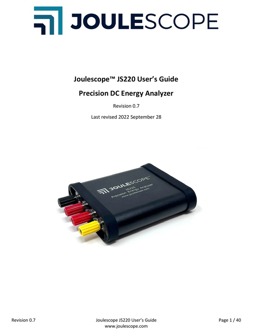
Joulescope™ JS110 User’s Guide
Precision DC Energy Analyzer
Revision 1.0
Last revised 2020 June 27

Revision 1.0 Joulescope JS110 User’s Guide Page 2 / 42
www.joulescope.com
1. Affordable, easy-to-use, accurate and precise
Multimeter view
Oscilloscope view
Applications include:
•Microprocessor and microcontroller power profiling and optimization
•Hardware power optimization
•Sleep current optimization
•Hardware and software troubleshooting
•Software characterization and interrupt service routine profiling
•USB 2.0 inrush and suspend current pre-compliance testing
•General-purpose current, voltage, power, charge, and energy measurement
The Joulescope™ JS110 is the most affordable and easy-to-use precision DC energy analyzer. It
measures current and voltage, then computes power and energy. Many modern battery-powered
devices and IoT devices have a high dynamic current range, which makes accurate measurement
difficult. When “sleeping”the devices consume nanoamps (nA) or microamps (µA), but when active,
they consume milliamps (mA) or amps (A). Joulescope combines high-speed sampling and rapid
dynamic current range switching to provide accurate and seamless current and energy measurements,
even for devices with rapidly varying current consumption. The unprecedented accuracy and low-cost
of Joulescope allows every engineer on the team to measure the energy consumed by the target device
during development. Joulescope provides rapid feedback on how changes affect the overall product
battery life.
Joulescope displays instantaneous voltage, current, power, and energy, like a multimeter. The
multimeter provides a quick and easy summary of the present state of your device.
Joulescope displays waveforms of voltage and current over time, like an oscilloscope. This oscilloscope
view allows you to identify and to troubleshoot dynamic behavior and short events, including inrush
current, event handlers, and tasks.

Revision 1.0 Joulescope JS110 User’s Guide Page 3 / 42
www.joulescope.com
2. Key benefits
•Dynamic range: Joulescope accurately measures electrical current over nine orders of
magnitude from amps down to nanoamps. This wide range allows accurate and precise current
measurements for modern devices. Sleep modes are often just nanoamps (nA) or microamps
(µA). Active modes are often milliamps (mA) or amps (A).
•Low voltage drop: Most multimeters and current meters have a significant voltage drop
(sometimes called burden voltage or insertion loss), which affects the actual voltage delivered to
the device under test. Joulescope has a total voltage drop of 25 mV at 1 A, which keeps your
target device running correctly. Joulescope’s extremely fast current range switching maintains
low voltage drop even under rapidly varying current demands.
•Makes the invisible visible:Joulescopes measure current and voltage 2 million times per
second with 250 kHz bandwidth. This high sampling rate makes the power consumption of
interrupt service routines, inrush currents, and other short events visible.
•Easy to use: Joulescope reports cumulative energy consumption along with real-time current,
voltage, and power. The multimeter view clearly shows the most recent value, while the
oscilloscope view allows you to explore changes over time. Much simpler and more accurate
than anything in its class!
•Customizable: The Joulescope host software is open source on GitHub. You can also swap the
banana jack front panel with front panels that have other connector types. The front panels are
open source on GitHub.
•Portable: Joulescope fits in your backpack and only needs a small part of your desk. Take
Joulescope wherever you want to use it!
•Affordable: Joulescope is affordable and priced so that every developer on the team can have
one at their desk. With such convenient access, Joulescope allows developers to see the impact
of their changes on energy consumption immediately. Developers can make informed choices
to account for battery life during design. Eliminate power consumption surprises during final
product testing!

Revision 1.0 Joulescope JS110 User’s Guide Page 4 / 42
www.joulescope.com
3. Key features
•-1V to 15V voltage range
•-1A to 3A current range, continuous
•Up to 10A current pulses (<10 ms, < 3A average per second)
•Down to 1.5 nA resolution, equivalent to 32-bits of dynamic range
•Synchronously measures voltage and current at 2 million samples per second, 14-bit
•250 kHz bandwidth
•Rapid 1 μs switching between shunt resistors for seamless dynamic current measurement
•Computes power, total energy, and charge
•Operates with minimal voltage disturbance between IN and OUT ports
•Up to ±48V common-mode voltage between USB ground and IN-, IN+, OUT+, and OUT-
•2 general-purpose inputs and 2 general-purpose outputs
•Programmable on/off for power cycling the target device and measuring inrush currents
•USB 2.0 high-speed host connectivity
•Host software support for Microsoft® Windows®, Apple® Mac® OS X®, and Linux®
•Host software provides real-time graphs of current, voltage, and power over time
•Host software is open source and available on GitHub
•Swappable front panel with open-source designs on GitHub
•Firmware upgradable
See Section 8 for the full specifications.

Revision 1.0 Joulescope JS110 User’s Guide Page 5 / 42
www.joulescope.com
4. Table of contents
1. Affordable, easy-to-use, accurate and precise .....................................................................................2
2. Key benefits...........................................................................................................................................3
3. Key features ..........................................................................................................................................4
4. Table of contents ..................................................................................................................................5
5. What comes in the box.........................................................................................................................7
6. Meet Your Joulescope...........................................................................................................................8
7. Quick start.............................................................................................................................................9
8. Specifications ......................................................................................................................................11
8.1. Absolute maximum ratings.........................................................................................................11
8.2. Mechanical..................................................................................................................................11
8.3. Recommended operating conditions..........................................................................................11
8.4. Specification conditions..............................................................................................................11
8.5. Current measurement specifications..........................................................................................12
8.6. Voltage measurement specifications..........................................................................................12
8.7. General specifications.................................................................................................................12
8.8. Parasitic effects specifications....................................................................................................12
8.9. Software-controlled fuse specifications .....................................................................................12
8.10. General Purpose Inputs & Outputs.........................................................................................13
9. Host software......................................................................................................................................14
9.1. Installation ..................................................................................................................................14
9.1.1. Linux....................................................................................................................................14
9.1.2. Windows 7 ..........................................................................................................................14
9.1.3. macOS .................................................................................................................................14
9.2. Multimeter view .........................................................................................................................15
9.3. Oscilloscope view........................................................................................................................16
9.4. Energy and Charge......................................................................................................................19
9.5. Open-source................................................................................................................................19
10. Theory of operation........................................................................................................................21
10.1. Ammeter .................................................................................................................................21
10.2. Voltmeter................................................................................................................................22
10.3. Host Computer........................................................................................................................22
10.4. Power, Energy, Charge, and Statistics.....................................................................................22

Revision 1.0 Joulescope JS110 User’s Guide Page 6 / 42
www.joulescope.com
10.5. High impedance / low leakage................................................................................................23
10.6. Electrical isolation...................................................................................................................23
11. How to swap the front panel ..........................................................................................................24
12. GPI & GPO .......................................................................................................................................25
13. Electrical Isolation...........................................................................................................................27
14. Typical Behavior..............................................................................................................................28
14.1. Step Response.........................................................................................................................28
15. Compliance .....................................................................................................................................31
15.1. United States...........................................................................................................................31
15.1.1. FCC Notice...........................................................................................................................31
15.2. Europe.....................................................................................................................................31
15.3. Safety ......................................................................................................................................31
15.4. RoHS Directive 2011/65/EU, 2015/863/EU ............................................................................31
15.5. Country of origin .....................................................................................................................32
16. Maintenance...................................................................................................................................33
16.1. Verification Procedure ............................................................................................................33
16.1.1. Preliminary operations........................................................................................................33
16.1.2. Voltage Validation Process..................................................................................................33
16.1.3. Current Validation Process..................................................................................................34
17. Warranty.........................................................................................................................................37
18. Contact............................................................................................................................................38
19. Glossary...........................................................................................................................................39
20. User’s guide information ................................................................................................................41
20.1. Copyright notice......................................................................................................................41
20.2. Publisher .................................................................................................................................41
20.3. Warranty .................................................................................................................................41
20.4. Change log...............................................................................................................................42

Revision 1.0 Joulescope JS110 User’s Guide Page 7 / 42
www.joulescope.com
5. What comes in the box
Your Joulescope JS110 purchase includes:
•Joulescope JS110 instrument
•Banana Jack Front Panel, already installed
•6’ USB 2.0 A to B cable
•T15 Torx screwdriver
•Quick Start Guide
•Joulescope sticker
You will need to provide:
•A host computer which must be running Microsoft® Windows® 10, Window 7, Apple® Mac®
OS/X® or Linux®. Most computers manufactured within the last five years should work. The
computer requires an available USB 2.0 port, at least 500 MB of hard drive / solid state drive
storage space, and 1 GB of available RAM.
•Suitable cable(s) to connect Joulescope to your power source
•Suitable cable(s) to connect Joulescope to your target device.
You need an internet connection to download the free software.

Revision 1.0 Joulescope JS110 User’s Guide Page 8 / 42
www.joulescope.com
6. Meet Your Joulescope
The front side of Joulescope has the connectors that connected to your target device and its regular
power supply. Connect your power supply positive output to IN+, and connect OUT+ to your target
device’s positive voltage input. Connect the target device’s ground or negative voltage input to OUT-.
Connect IN- to your power supply ground or negative output.
The LED indicates when your Joulescope is ready to collect measurements.
The backside of Joulescope has the host USB connector, status LED, and GPIO connector:
Use the provided USB cable to connect the USB host computer connector to your host computer. The
status LED indicates when the Joulescope successfully communicates with the host computer. For
Windows hosts, the Status LED illuminates shortly after connecting the Joulescope to the computer. For
Linux and macOS hosts, the Status LED will not illuminate until the Joulescope software attempts to
connect.
The GPIO connector provides two general-purpose inputs and two general-purpose outputs. See
Section 12 for details.

Revision 1.0 Joulescope JS110 User’s Guide Page 9 / 42
www.joulescope.com
7. Quick start
Download the host software from http://www.joulescope.com/download. Follow the instructions on
the download page to install the software for your platform. Linux, macOS, and Windows 7 may require
additional steps. See section 9.1 for details.
Start the Joulescope host software.
Connect the Joulescope USB port to the host computer using the provided USB cable.
The host software will automatically detect the connected Joulescope and start displaying data.

Revision 1.0 Joulescope JS110 User’s Guide Page 10 / 42
www.joulescope.com
Connect the Joulescope IN port to your power source. If using a configurable power supply, set the
voltage and current suitable for your device under test. The maximum voltage between IN+ and IN-
should never exceed ±15V. IN and OUT are electrically isolated from USB, but the voltage between any
port and USB ground should never exceed ±48V.
Connect the Joulescope “OUT” port to the power input for your device under test.
Operate your device under test. The Joulescope host software starts in the Multimeter view by default.
Use the Multimeter view to measure the current, voltage, power, charge, and energy consumption.
Dive into more detail with the oscilloscope view. Select View →Oscilloscope Default to display
waveforms of voltage, current, and power over time.

Revision 1.0 Joulescope JS110 User’s Guide Page 11 / 42
www.joulescope.com
8. Specifications
8.1. Absolute maximum ratings
Min
Max
Unit
USB voltage
-0.3
6
V
Max voltage applied between IN+ to IN-
-20
20
V
Max voltage applied between OUT+ to OUT-
-20
20
V
Max voltage to USB ground (IN+, IN-, OUT+, OUT-)
-48
48
V
Input current (powered, burst)
-10
10
A
Input current (powered, sustained)
-3
3
A
Input current (unpowered)
-0.5
N/A (off)
A
Storage temperature
-40
80
°C
Operating temperature
0
50
°C
Relative humidity (non-condensing)
0
95
%
Altitude from sea level
-100
2500
m
Max voltage applied to GPI relative to USB ground
-10
10
V
8.2. Mechanical
Typical
Unit
Weight
217
grams
Width
81
mm
Length (including banana jack front panel)
150
mm
Height
33
mm
8.3. Recommended operating conditions
Test condition
Min
Typical
Max
Unit
Operating temperature
10
40
°C
USB supply voltage
4.5
5.0
5.5
V
USB supply current
500
mA
Voltage applied to IN
-1.0
15
V
Input current
continuous
-1.5
3
A
Input current pulse
< 10 milliseconds,
< 3A average
10*
A
Input current pulse
< 100 milliseconds
< 3A average
5*
A
* Suitable for handling inrush currents when connecting capacitive loads.
8.4. Specification conditions
Temperature
23 °C ± 10 °C
Humidity
20% to 80% RH, non-condensing
Calibration interval
1 year*
* Recommended to comply with industry-standard practices, but Joulescope is designed not to need
recalibration.

Revision 1.0 Joulescope JS110 User’s Guide Page 12 / 42
www.joulescope.com
8.5. Current measurement specifications
Range
Accuracy
Resolution
Impedance
Bandwidth
10 A*
±0.3% ±7 mA
1 mA
0.01 Ω
250 kHz
2 A
±0.3% ±1.50 mA
175 µA
0.01 Ω
250 kHz
180 mA
±0.3% ±150 µA
15 µA
0.11 Ω
250 kHz
18 mA
±0.25% ±15 µA
1.5 µA
1.11 Ω
250 kHz
1.8 mA
±0.25% ±1.5 µA
150 nA
11.1 Ω
180 kHz
180 µA
±0.25% ±150 nA
15 nA
111 Ω
70 kHz
18 µA
±0.25% ±30 nA
1.5 nA
1111 Ω
15 kHz
* Joulescope is designed for 3 A sustained. See the recommended operating conditions for maximum
durations for higher currents.
Test current measurement bandwidth by varying the effective load impedance. Due to load
capacitance, altering the source voltage is not a valid method of testing current bandwidth.
8.6. Voltage measurement specifications
Range
Accuracy
Resolution
Impedance
Bandwidth
15 V
±0.1% ±11 mV
1.2 mV
-
250 kHz
5V
±0.1% ±3.5 mV
400 µV
-
250 kHz
8.7. General specifications
Test condition
Min
Typical
Max
Unit
Sampling frequency
25 °C
2000000
sps
Sampling frequency
25 °C
-20
20
ppm
Front panel insertions
100
8.8. Parasitic effects specifications
Test condition
Min
Typical
Max
Unit
Current leakage (IN+ to IN-)
25 °C, +3.3V
2
nA
Current leakage (IN+ to IN-)
25 °C, +5V
2
nA
Current leakage (IN+ to IN-)
25 °C, +15V
3
nA
Shunt resistor voltage, max
0 to 2 A, static
20
21
mV
Burden voltage (IN+ to OUT+)
< 1 A, banana jacks
0
25
30
mV
Burden voltage (OUT- to IN-)
< 1 A, banana jacks
0
3
8
mV
Shunt switching time
Over-range
< 100 ns rise time
0
0.8
1.2
µs
Over-range settling time
0
2
5
µs
Under-range settling time
0
2
5
µs
8.9. Software-controlled fuse specifications
Test condition
Min
Typical
Max
Unit
Current leakage (IN+ to OUT+)
25 °C, 3.3V
5
nA
Current leakage (IN+ to OUT+)
25 °C, 5V
7
nA
Current leakage (IN+ to OUT+)
25 °C, 15V
28
5000
nA

Revision 1.0 Joulescope JS110 User’s Guide Page 13 / 42
www.joulescope.com
8.10. General Purpose Inputs & Outputs
Test condition
Min
Typical
Max
Unit
Programmable logic level voltage
1.8
VUSB -
0.2
V
Input leakage per pin
25 °C
±1
μA
Input leakage per pin
±2
μA
Output voltage high
-100 μA
Vcco-
0.1
V
Output voltage high
-4 mA @ 1.65 V
1.2
V
Output voltage high
-8 mA @ 1.65 V
1.9
V
Output voltage high
-24 mA @ 1.65 V
2.4
V
Output voltage high
-32 mA @ 1.65 V
3.8
V
Output voltage low
100 μA
0.1
V
Output voltage low
4 mA @ 1.65 V
0.45
V
Output voltage low
8 mA @ 2.3 V
0.3
V
Output voltage low
24 mA @ 3 V
0.55
V
Output voltage low
32 mA @ 4.5 V
0.55
V
Output impedance
10 mA
90
100
110
Ω
GPI sample rate
2
MSPS
Continuous output current
Per pin
±50
mA
Total power dissipation
Over output impedance
0.25
W
The Joulescope uses the TI SN74LVC2T45 for both the GPIs and GPOs. See the SN74LVC2T45 datasheet
for more information. Both the GPIs and GPOs are protected with the Vishay VEMI45AA-HNH, which is
an EMI filter with ESD protection. The VEMI45AA is a pi filter with 100 Ohm resistance and capacitance
between 29 pF and 60 pF.
GPIO Supply
Min
Typical
Max
Unit
+5V output
4.4V
VBUS –0.1
5.5
V
Current
100
mA
Output impedance
1
Ω

Revision 1.0 Joulescope JS110 User’s Guide Page 14 / 42
www.joulescope.com
9. Host software
The Joulescope host software runs on a host computer and communicates with the Joulescope
instrument over USB 2.0 high-speed.
The software works with Microsoft® Windows® 10, Windows® 7, Apple® Mac® OS/X®, and Linux®. For
Linux, only Ubuntu 18.04.1 LTS is tested. The Joulescope software only supports 64-bit operating
systems with 64-bit python 3.6+.
9.1. Installation
The Joulescope software is available to download at
www.joulescope.com/download/
Click on the download link for your platform. For a list of all releases for all platforms, see
https://download.joulescope.com/joulescope_install/index.html
Follow the usual process to download and install the software following the on-screen directions.
Several operating systems may require additional steps, as noted below.
We recommend installing the Joulescope software on the native operating system, not under a virtual
machine, due to Joulescope’s demanding USB communication requirements.
9.1.1. Linux
Many Linux systems, including Ubuntu, use “udev” to manage devices and grant permissions. You will
need to install a udev rule that grants Joulescope hardware access to your account. Download and
follow the instructions in this file:
https://raw.githubusercontent.com/jetperch/pyjoulescope/master/99-joulescope.rules
9.1.2. Windows 7
Windows 10 and many Windows 7 machines will run without additional steps. However, some
Windows 7 machines do not include Microsoft’s WinUSB, the driver used by Joulescopes. You will need
to install the driver manually.
1. Download https://raw.githubusercontent.com/jetperch/pyjoulescope/develop/joulescope.inf
2. In the Windows →Run bar, type devmgmt.msc
3. Right-click on Joulescope, select “Update Driver Software…”
4. Select “Browse my computer for driver software”
5. Browse to the directory where you downloaded the joulescope.inf file
6. The driver should install, and your Joulescope should no longer have a yellow exclamation mark
9.1.3. macOS
The macOS distribution is currently signed, but it is not distributed through the Apple Store. Newer
versions of macOS, such as Catana, indicate security warnings. You may need to control-click the
Joulescope application, then select “open” to bypass these security warnings. You will need to repeat
the control-click, “open” process several times (usually twice) until macOS finally allows the Joulescope
software to launch. After granting this permission once, subsequent runs will run normally.

Revision 1.0 Joulescope JS110 User’s Guide Page 15 / 42
www.joulescope.com
9.2. Multimeter view
Upon launching the host software, you see the multimeter view:
You can return to this view at any time using View →Multimeter.
The multimeter view provides the present operating state at a glance. The multimeter view displays
several quantities:
•Electrical current in amperes (A)
•Electrical voltage in volts (V)
•Power in watts (W)
•Energy in joules (J)
•Charge in either coulombs (C) or amp-hours (Ah).
This display, along with all other value displays in the Joulescope software, the SI standard prefixes for
orders of magnitude:
Prefix
Power
Name
G
109
giga-
M
106
mega-
k
103
kilo-
m
10-3
milli-
µ
10-6
micro-
n
10-9
nano-
p
10-12
pico-

Revision 1.0 Joulescope JS110 User’s Guide Page 16 / 42
www.joulescope.com
The multimeter view updates every half second (0.5 seconds) by default. The software computes and
displays the statistics over each half-second time window. The large numbers are the mean (also called
average) value of that quantity over the window. The software also displays:
•σ: The standard deviation
•min: The minimum value
•max: The maximum value
•p2p: The peak-to-peak value, which is equal to (max –min)
Note that energy does not display these additional statistics since they are not meaningful.
Every update represents only the data recorded over the last half-second. If you click on the
“Accumulate” button to activate it, then the software extends the statistics to combine each new half-
second window without discarding results from previous windows.
9.3. Oscilloscope view
The software includes an oscilloscope view. Click View →Oscilloscope.
The first view allows you to control the connected Joulescope. Press to pause or resume capturing
live data. Press to start and stop recording data to a file. This feature is only available when the
device is capturing live data.
Current Range allows you to select Joulescope’s active shunt resistor. Most applications use auto,
where Joulescope automatically selects the best range. However, you can manually force the range.
Select off to disconnect power to the target device.

Revision 1.0 Joulescope JS110 User’s Guide Page 17 / 42
www.joulescope.com
Voltage Range allows you to select the voltage range. Joulescope includes a 15V range and a more
sensitive 5V range.
The Control widget in the Oscilloscope view also displays the energy or current consumed. Left-click or
select Tools →Clear Accumulators to reset the accumulators to zero. Right-click or use File →
Preferences → Units → Accumulator to set the displayed field to either energy or current.
The software displays two different waveforms by default. The top waveform is electrical current, and
the bottom waveform is electrical voltage. The x-axis is time. If you have a Joulescope connected, it will
automatically add the most recent data to the right of the waveform and shift existing data to the left.
The y-axis data is the value measured at the corresponding point in time. Joulescope captures data 2
million times per second. When zoomed out, each x-axis pixel may represent many, many samples,
which are that pixel’s sample window. The plot displays the statistics over each pixel. The yellow line is
the mean (average). The red lines are the minimum and maximum. Power glitches, such as interrupt
service routines, are very interesting for energy optimization. The minimum and maximum ensure that
you do not miss these events, even when zoomed out. When you eventually zoom in far enough, the
red lines disappear because 1 pixel becomes 1 sample, and the minimum and the maximum are the
same as the average. You can use File → Preferences → Waveform → show_min_max to disable these
lines or display the minimum to maximum region as a fill instead.
The software computes statistics quantities over the full-time window shown in the present view for
each waveform. The software displays the statistics on the right edge of the window. The statistical
quantities are:
•µ: The mean (also called average) value
•σ: The standard deviation
•p2p: The peak-to-peak value (max - –in)
•min: The minimum value
•max: The maximum value
•∫: The integral over the time window
The waveform view supports Annotations to present additional information, which includes:
•A Single Marker that display information at a single point. Names used by other equipment for
this feature include marker and cursor.
•Dual Markers that display information over a time window. Names used by other equipment
for this feature include cursors, timing markers, window, and range selection.
To display statistics at a single point, move the mouse to the x-axis time labels near the top. Then right-
click (control-click on Mac OS) to bring up the context menu. Select Annotations → Single Marker.

Revision 1.0 Joulescope JS110 User’s Guide Page 18 / 42
www.joulescope.com
Left-click the marker to move it with the mouse. As you move the mouse over the waveforms, the
vertical marker follows along. The line displays statistics about that location:
•t: The sample time for the displayed sample or window
•µ: The mean (also called average) value
When the location contains more than one sample per displayed pixel, the line displays statistics over
that single pixel’s sample window:
•σ: The standard deviation
•p2p: The peak-to-peak value (max - –in)
•min: The minimum value
•max: The maximum value
Left-click again to keep the marker in position.
To display statistics over a selectable range, right-click on the x-axis time labels and select Annotations
→ Dual Markers. Left-click a marker to move it with the mouse, then left-click again to stop moving the
marker. Hold the Ctrl key while left-clicking to move both markers together. Right-click (control-click on
Mac OS) on one of the dual markers to export data or perform analysis over the selected range.
Use the scroll wheel to zoom in and zoom out. The zoom operation keeps the point under the mouse
cursor at the same location after the zoom operation. However, when you reach the maximum extents
while zooming out, that point may move. When viewing live data, the zoom operation always keeps the
most recent data in view at the right.

Revision 1.0 Joulescope JS110 User’s Guide Page 19 / 42
www.joulescope.com
Press the left mouse button and drag the cursor left or right to pan in time. Pan is not supported when
viewing live data from a Joulescope.
The software displays the waveform on a linear scale with automatic y-axis ranging by default. The y-
axis context menu has additional options. Right-click (control-click on Mac OS) on the y-axis to display
the menu.
When manual ranging is activated, hover over the y-axis and use the scroll wheel to zoom in and out.
Left-click and drag up and down to pan the y-axis.
Use the y-axis context menu to change the y-axis scale mode. The y-axis displays in linear coordinates
by default but also supports a logarithmic scale. A logarithmic scale is handy to view wide dynamic
ranges for current and power.
Use the y-axis context menu to hide the signal. Click Settings at the top left to display the settings
menu. Select Add → [Signal Name]to display a signal not already shown.
9.4. Energy and Charge
The Joulescope measures current and voltage two million times per second. It then multiplies current
by voltage to compute power. Joulescope then integrates power over time to compute energy. It also
integrates current to compute charge. Joulescope displays energy in both the Multimeter view and
Oscilloscope view. This value starts accumulating when the software starts. Use Tools →Clear Energy
to reset it to zero at any time.
The energy value and charge value provide a simple measurement to observe changes, especially for
software. You can baseline the performance of an operation by recording the measured energy or
charge value. You can then make changes, repeat the test, and observe the new energy or charge value.
The oscilloscope view enables you to investigate in further detail.
9.5. Open-source
The host software is open source and written in Python 3.6+. The host software consists of two layers:
Repo name
Python package name
Description
pyjoulescope_ui
joulescope_ui
The Joulescope User Interface written in QT/PySide2
pyjoulescope
joulescope
The Joulescope “driver” which enables scripting

Revision 1.0 Joulescope JS110 User’s Guide Page 20 / 42
www.joulescope.com
The joulescope package was designed so that you can script custom Joulescope actions and integrate
Joulescope into your applications.
See the GitHub repositories for the latest details.
https://github.com/jetperch/pyjoulescope_ui
https://github.com/jetperch/pyjoulescope
You can find examples for how to use Joulescope in your Python application at:
https://github.com/jetperch/pyjoulescope_examples
Also see the documentation:
https://joulescope.readthedocs.io/
The Joulescope software depends upon other software and libraries. See CREDITS.html for
pyjoulescope_ui and pyjoulescope.
Table of contents
Other JETPERCH Measuring Instrument manuals
Popular Measuring Instrument manuals by other brands

BBE
BBE MOVISTROB 3000 Series instruction manual

ITS Telecom
ITS Telecom 1RU8126MS user manual

PCB Piezotronics
PCB Piezotronics IMI SENSORS 608A11/020BZ Installation and operating manual

Laserworld
Laserworld BLUE-300-473 manual

PCB
PCB Piezotronics M1631-03C Installation and operating manual

Center
Center 340 instruction manual