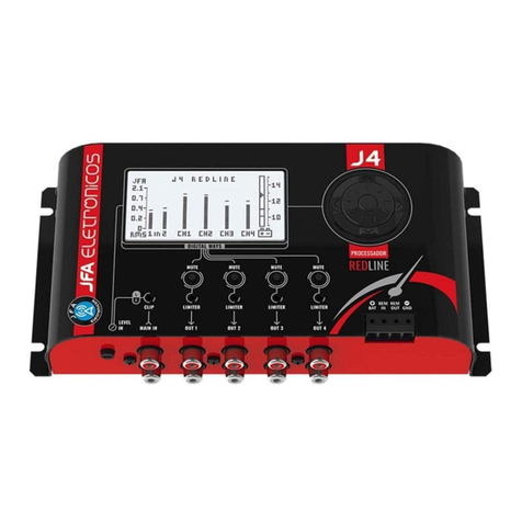
JFA Electronicos J4 Pro User manual

AUDIO PROCESSOR PRO
USER MANUAL

AUDIO PROCESSOR PRO

Navigation ScrollGraphic display
Led indicator
Excess entry level
PRESENTATION
The J4 PRO Processor is a digital audio processor with 2 inputs and 4 outputs, which can be
congured independently.
It has a display for real-time visualization of input and output levels, simulating the function of
an oscilloscope, as well as a potentiometer for adjusting the maximum level of input audio.
Led indicators
MUTE / LIMITER per channel
MUTE switch per channel
Level adjustment
maximum input
Input
L e R
Output
1, 2, 3 e 4
Battery Positive
_ GND
REM Output
REM Input

IMPORTANT RECOMMENDATIONS:
A The recommended wiring gauge is 1.5mm² for the positive-negative wires and 0.50mm² for
the wires of the remote. The J4 Pro Processor must be attached to a stable base and easily
accessible, away from heat sources. It is not recommended to install the product on the sides of
the speakers due to vibration. Do not attach directly to the bodywork of the vehicle.
Never feed the J4 Pro Processor from the vehicle's original wiring. To avoid noise pickup, use
shielded signal cables. These can not be passed together with the power cables and should be
as short as possible. Observe the cable crossing points. Sharp edges of the bodywork or sharp
corners can cut them, causing future problems.
The J4 Pro Processor must be connected before the ampliers. Failure to do so may result in
damage to the speakers. For the purpose of safe operation of the ampliers, the J4 Pro processor
has a REMOTE OUT output, which sends the + 12V signal after the crossover is activated.
CONNECTION DIAGRAM
IMPORTANT: Any connection of the power, input or output connectors should only be
made with the appliance switched off.
Connect on
RCA output
main
player
Connect the power cables according to the diagram below.
Check out the example of how the outputs can be congured, remembering that the outputs can
be congured in other ways.
Connect on
remote input
two ampliers
Connect on
remote output
player
Amplier
1
Output 1
Amplier
2
Output 2
Amplier
3
Output 3
Amplier
4
Output 4
Adjust level
input

GRAPHIC SCREEN AND NAVIGATION SYSTEM
We recommend that when working with the J4 Pro Processor, always keep the instruction
manual handy so that you can consult it whenever necessary.
Usage Time Pink noise
Prole Selection
Select / return button
Directional arrows
Scroll level selector
in the submenus
Crossover / Delay / Limiter / EQ ChannelEqualizationOutput level
HOME MENU
NAVIGATION SCROLL
Pressing the selector button and
the directional arrow blocks and
unlocks access the settings
1/4 2/4 3/4 4/4

LEVEL METER (OSCILLOSCOPE FUNCTION)
Peak storage
Vpp level of the independent outputs
Vpp level of inputs
Customizable presentation text
Pressing the screen for 5 seconds
of the level meter, enters the
of the presentation text.
To exit, simply press the central key.
Supports up to 16 characters

LEVEL
Level adjustment
independent
Master level adjustment
SEMI-PARAMETRIC EQUALIZER
Memory for 3 custom settings
Allows you to adjust the frequency
and the gain of each band

X-OVER
Output channel number
Input R + L, R or R routing
High-pass lter frequency
High-pass lter type (See addendum 1)
Low-pass lter frequency
Low-pass lter type (See addendum 1)
SCREEN 1/4
Changes the phase by 0 ° or 180 °
Delay signal in millimeters
SCREEN 2/4

X-OVER
Output channel number
Turns the limiter function on / off
Value in dB and Vpp of the point
of limiter's performance
Limiter response time
Limiter recovery time
SCREEN 3/4
SCREEN 4/4
Adjusting the frequency and
factor of merit "Q”
Parametric equalizer

PROFILE
3 Proles to save processor settings
In each prole, up to 3
semi-parametric equalizations
can be congured
Allows you to download settings
from one prole to another
Sample copy of PROFILE 1 for PROFILE 2
Allows you to download settings
from one prole to another

PINK NOISE
TIME
Time Reset
of work
Time Reset
of work
Output range adjustment
On/Off
General usage counter
of the processor

ADDENDUM 01 - FILTER OPTIONS FOR THE X-OVER
The J4 PRO processor has 3 lter structures for cutting in the X-OVER menu, BUT = Butte Work,
BES = Bessel and LK = Link Witz, in addition to OFF = lters off.
BUT cuts in 6, 12, 18, 24 dB/8ª
BES cuts in 12, 24 dB/8ª
LK cuts in 12, 24, 36, 48 dB/8ª
ADDENDUM 02 - LIMITER USE OF THRESHOLD, ATTACK AND RELEASE
THRESHOLD - Denes from which level the limiter acts.
The range can be adjusted from 1.4 to 7.0 Vpp.
Limiter starts
to act from
of this level

ATTACK - It's the limiter's response time. When in AUTO (recommended), the time is set as
follows:
Example:
RELEASE - It is the limiter recovery time. When in AUTO (recommended), this time is 16 times
longer than the ATTACK time.
See table of values below:
T = ( 1
Frequency Low Pass
(
x 1,5
T =
(
152
)
x 1,5 = 9,8ms
1
ATTACK Slow
+
RELEASE Slow
Advantage
1- Preserves the dynamics and "Robust" of the audio
2 - Discreet and smooth performance
3 - The music peaks are preserved
Desvantagem 1 - Low protection against audio peaks
Recomendado 1 - In audios with longer musical notes
2 - With low battery presence
ATTACK Slow
+
RELEASE Fast
Advantage
Desvantagem 1 - The system receives a rst Peak until it enters into action
Recomendado 1 - For audios that have a following sequence
of fast transients.
1 - Back rmness, impact and "punch" the audio beats
ATTACK Fast
+
RELEASE Fast
Advantage
Disadvantage 1 - Loss of audio dynamics
Recommended
1 - When you want more protection
2 - When you want to highlight less audible harmonics,
increasing the feeling of the environment
1 - System protection against Clipp
ATTACK Fast
+
RELEASE Slow
(Mode AUTO
of J4 Pro)
Advantage
Desvantagem 1 - The system receives a rst Peak until it enters into action
Recomendado 1 - For all types of audio where you want a reproduction
closest to the original
1 - Efcient Peak Control with discrete actuation
of the audio compressor
ADDENDUM 02 - LIMITER USE OF THRESHOLD, ATTACK AND RELEASE

TECHNICAL CHARACTERISTICS
Input channels
Output channels
Frequency response
Master semi-parametric equalizer
Parametric equalizer per channel
DSP lter, 24-bit hi-pass and low-pass
Total harmonic distortion (THD)
20Hz to 30kHz signal to noise ratio
Phase
Delay
Maximum input level
Maximum output level
Bar graph
Dimensions in millimeters (W x H x D)
Weight in grams
2
4
20Hz to 20kHz
15 bands -10 to + 10dB
1 band -12 to + 12dB
20Hz to 20KHz, (off / 6/12/18/24/36 and 48dB / 8 °)
0.002% at 1kHz
> 90dB
0 and 180 °
0 to 287cm
3.8Vpp / 10KΩ
15Vpp / 470Ω
0 to 6Vpp with "hold peaks"
202 x 103 x 43
480

AUDIO PROCESSOR PRO

www.jfaeletronicos.com
See all the automotive line products on our website.
Table of contents
Other JFA Electronicos Computer Hardware manuals