JGR sx8 User manual

SX8 Optical Switch
User Manual
All information contained herein is believed to be accurate and is subject to change
without notice. No responsibility is assumed for its use. JGR Optics Inc, 2011.


SX8 User Manual
G-UM-00004 Rev 006
3 of 45
IN THIS GUIDE:
IN THIS GUIDE .....................................................................................3
GENERAL INFORMATION.................................................................5
Key Features .................................................................................. 5
Applications ................................................................................... 5
Accessories .................................................................................... 6
Specifications ................................................................................. 6
Compliance .................................................................................... 7
FDA-CDRH Compliance ............................................................. 7
CSA / IEC Compliance ............................................................... 7
GETTING STARTED ............................................................................8
Initial Inspection............................................................................. 8
Operational Requirements .............................................................. 9
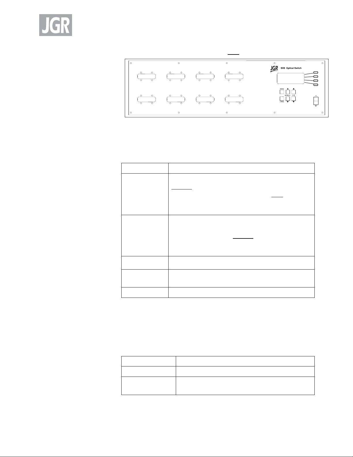
Product Overview........................................................................... 9
Front Panel and Key Description................................................ 9
Rear Panel ......................................................................... 10
OPERATION ....................................................................................... 11
Powering Up the Switch ................................................................ 11
User Menu Operation ................................................................... 11
Accessing the User Menu........................................................ 11
Messages and Symbols ................................................................. 13
PROGRAMMING GUIDE.................................................................. 15
Setting up for RS-232 or GPIB communication ................................ 15
Accessing the “User Menu” mode ........................................... 15
JDSU Optical Switch Compatibility ........................................... 15
Programming over GPIB ......................................................... 15
Programming Over RS-232...................................................... 15
Syntax and Style ........................................................................... 16
Program Message Formats ..................................................... 16
Terminating a Program Message ............................................. 16
Command Header Variations .................................................. 16
Specifying the Command Path ................................................ 17
Default Commands ................................................................ 17
Implemented Status Structures ............................................... 18
Queues ........................................................................................ 24
Input Queue ......................................................................... 24
Output Queue ....................................................................... 24
Error Queue ........................................................................ `24
Description of Error Numbers ........................................................ 25
IEEE 488.2 Common Commands and the SCPI Command Tree.......... 26
IEEE 488.2 Common Commands.............................................. 26
SCPI Command Tree ............................................................... 26
Description of Individual Commands .............................................. 28
Common Commands .............................................................. 28

SX8 User Manual
G-UM-00004 Rev 006
4 of 45
Status Commands .................................................................. 31
MAINTENANCE AND TROUBLESHOOTING.............................. 39
Maintenance................................................................................ 39
Cleaning the Unit ................................................................... 39
Cleaning the Connector Ends (for Bulkhead Versions only) ........ 39
Cleaning Connectors .............................................................. 39
SAFETY................................................................................................ 41
Safety Symbols ............................................................................. 41
Classification ................................................................................ 42
Safety Instructions........................................................................ 42
Electrical Shock Hazards: ........................................................ 42
Fuse Replacement.................................................................. 42
Disconnecting from Line Power ............................................... 43
Environmental Hazards........................................................... 43
Laser Hazards ........................................................................ 43
Other Hazards........................................................................ 43
STORING AND SHIPPING............................................................... 45
Returning Shipments to JGR Optics ................................................ 45
Contact Information ..................................................................... 45

SX8 User Manual
G-UM-00004 Rev 006
5 of 45
1
GENERAL INFORMATION
This user’s manual for the SX8 Series Optical Switch contains complete
operating instructions. The SX8 Series Optical Switch can be ordered as
a single-mode or multimode model. The inspection report and a
description of any customer-requested information can be found in the
Test Report document envelope.
The SX8 Series Optical Switches offer low insertion loss, and very high
stability and repeatability needed to meet the stringent test,
measurement, and manufacturing system requirements.
In addition to manual front panel operation, the SX8 switch may be
operated over the RS-232 serial interface and IEEE 488 GPIB parallel
interface. Please refer to the PROGRAMMING GUIDE section on page 15
for more information.
Key Features
Low IL (0.7 dB)
Up to 360 outputs
Up to 4 inputs
Many configuration possibilities
User friendly
RS-232 serial and IEEE 488 GPIB parallel interface
Applications
High-volume production testing
Multiple device testing
R&D applications

SX8 User Manual
G-UM-00004 Rev 006
6 of 45
System compliance testing
Accessories
AC power cord
User’s manual
Test Report
Specifications
The following optical specifications describe the warranted
characteristics of the unit. Supplementary specifications describe the
typical non-warranted performance of the unit.
Table 1: Optical/Electrical Specifications
Parameter
Specification
Single-Mode
Multimode
Wavelength Range
1250 - 1670 nm
840 - 1350 nm
Fiber Type
9/125 μm
50/125 or
62.5/125 μm
Insertion Loss*
0.7 dB
Backreflection
≤ - 60 dB
≤ - 40 dB
PDL
0.05 dB
-
Stability
± 0.03 dB
Repeatability
0.005 dB
Crosstalk (maximum)
-80 dB
Maximum Input Power
300 mW
Switching Time
one channel
each additional channel
300 ms
+12 ms
Input Voltage
100 - 240 V AC, 50 - 60 Hz
Power Consumption
150 VA maximum
Control
Front Panel/GPIB/RS232
* excluding connectors

SX8 User Manual
G-UM-00004 Rev 006
7 of 45
Table 2: Other Specifications
Parameter
Specification
Dimensions W x H x D (3U/6U)
48 x 13.5 x 37.5/48 x 27 x 37.5 cm
Weight
15 kg (depending on
configuration)
Operating Temperature
0 to 55 °C
Storage Temperature
-40 to 70 °C
Humidity (Non-condensing)
Maximum 95% RH from 0 to 40 °C
Compliance
FDA-CDRH Compliance
Under the US Food and Drug Administration (FDA) Center for Devices
and Radiological Health (CDRH), the unit complies with the Code of
Federal Regulations (CFR), Title 21, Subchapter J, which pertains to laser
safety and labeling. See the link below for more information.
http://www.accessdata.fda.gov/scripts/cdrh/cfdocs/cfcfr/CFRSe
arch.cfm?CFRPartFrom=1000&CFRPartTo=1050
CSA / IEC Compliance
The unit complies with certain standards of the Canadian Standards
Association (CSA) and the International Electrotechnical Commission
(IEC).
The unit is in Installation Category (Overvoltage Category) II under IEC
664. IEC 664 relates to impulse voltage levels and insulation
coordination. The particular category is defined as: local level,
appliances, portable equipment, etc, with smaller transient
overvoltages than Installation Category (Overvoltage Category) III.
The unit is in the Pollution Degree 2 category under IEC 1010-1 and
CAN/CSA-C22.2 No. 1010.1. The IEC standard on Safety Requirements
for Electrical Equipment for Measurement, Control, and Laboratory Use
relates to insulation coordination. The CSA standard is on Safety
Requirements for Electrical Equipment for Measurement Control, and
Laboratory Use, Part I: General Requirements. The Pollution Degree 2
category is defined as follows: “Normally only non-conductive pollution
occurs. Occasionally, however, a temporary conductivity caused by
condensation must be expected.”

SX8 User Manual
G-UM-00004 Rev 006
8 of 45
2
GETTING STARTED
Caution
To avoid the risk of injury or death,
always observe the precautions listed in
the SAFETY on page 41.
This user’s manual contains complete operating instructions for the safe
and effective operation of the SX8 Optical Switch. It is recommended
that users of the SX8 familiarize themselves with contents of this
manual.
The inspection report and a description of any customer-requested
information may be found in the calibration document envelope
included with the instrument.
Initial Inspection
Warning
To avoid electrical shock, do not initialize or
operate the unit if it bears any sign of damage.
Ensure that the unit and any devices or cords
connected to it are properly grounded.
Inspect the package and contents for signs of damage.
Ensure all contents are included:
SX8 Series Optical Switch
1 AC power cord
User’s manual
Test report
Read the user’s manual thoroughly, and become familiar with all
safety symbols and instructions to ensure that the unit is operated
and maintained safely.
Ensure the unit is operational:
Connect the unit to the power source using the power cord
provided.
Set the power switch to ON to initialize the SX8 switch, and
observe the power-up sequence. The version number of the

SX8 User Manual
G-UM-00004 Rev 006
9 of 45
firmware is displayed. The message “Initializing” is displayed
momentarily.
Set the power switch to OFF and disconnect the switch.
Keep the packaging.
Immediately inform JGR Optics and, if necessary, the carrier if the
contents of the shipment are incomplete, if the unit or any of its
components are damaged or defective, or if the unit does not pass
the initial inspection.
Operational Requirements
In order for the unit to meet the warranted specifications the operating
environment must meet the following conditions for altitude,
temperature, humidity, and voltage.
Table 3: Environmental Requirements
Parameter
Specification
Altitude
Up to 2000 m
Temperature
Range of 0 to 40 °C
Humidity
Up to 95% humidity (0 to 40 °C)
c
Main supply voltage fluctuations must
not exceed ±10% of the nominal voltage
Product Overview
Front Panel and Key Description
The switch front panel will vary with model ordered. Two front panel
key pad configurations are shown in Figure 1 and Figure 2. They are
described in Table 4.
Figure 1: Front of the Switch (Models without SOFT KEYS)

SX8 User Manual
G-UM-00004 Rev 006
10 of 45
Figure 2: Front of the Switch (Models with SOFT KEYS)
Table 4: Operating Keys and Status LEDs
Key/LED
Description
I/O
Power ON / OFF switch.
MENU
Used to turn the Menu mode on and off. On models
without the SOFT KEYS, press the MENU key to go to
the next menu option. On models with the SOFT
KEYS, when deeper menu levels are selected, press
the MENU key to step back one level at a time.
LOCAL
Returns the meter back to Local (front panel
operation) mode when operating remotely (with GPIB
or RS-232). On models without the SOFT KEYS, when
in MENU mode, press the LOCAL key to go to the
previous menu option.
MODULE
Selects the optical switch module.
CHANNEL
Selects the output channel and adjusts the values in
MENU mode.
SOFT KEYS
When present, used to select the menu options.
Rear Panel
The rear-panel features are described in Table 5.
Table 5: Rear Panel Components
Component
Function
RS-232C
RS-232C serial interface port
IEEE 488 (GPIB)
GPIB (IEEE 488.1) interface port
~LINE
Power Input (also contains the user-replaceable
fuse)

SX8 User Manual
G-UM-00004 Rev 006
11 of 45
3
OPERATION
Powering Up the Switch
To power up the switch:
1. Connect the meter to an AC power source using the power cord
provided. If the meter has been running, ensure that the meter
is powered off and restarted.
2. Set the power switch to I (ON), and wait for the “Initialization”
process to finish.
3. Allow 30 minutes warm-up time in order to obtain a stable
performance.
User Menu Operation
Accessing the User Menu
To access the User Menu:
1. Press the “MENU” button to enter the User Menu mode.
2. User Menu Options are shown in Table 6 and Table 7
3. For models without the SOFT KEYS: Use the MENU button and
the LCL button to navigate through the menu options.
4. For models with the SOFT KEYS: Use the MENU button and the
SOFT KEYS to navigate through the menu options
5. Use UP/DOWN keys to select options or change values.

SX8 User Manual
G-UM-00004 Rev 006
12 of 45
Table 6: User Menu Options (Models without SOFT KEYS)
Options
Note
BAUD RATE:_____
Default:9600
Choose a Baud Rate from 1200 to
57600.
GPIB ADDR:__
Default:21
Select a GPIB address from 01 to 30.
JDS Compatible? Y/N
Default: N
Select between JGR (N) and JDS(Y)
modes.
Emulate JDS SB/SC or JDS
SX?
If JDS compatible is set to Yes(Y),
select between JDS SB/SC and SX
modes.
Save?
Quit?
Once changes are made the switch
returns to standard switching mode.
Table 7: User Menu Options (Models with SOFT KEYS)
Options
Note
REMOTE MENU
JGR SX8 COMMANDS/
Emulate JDS SB/SC or SX
Choose between JGR, JDS SB/SC or
JDS SX modes.
RS232 Baud:____
Default:9600
Choose a Baud Rate from 1200 to
57600.
GPIB Address:__
Default:21
Select a GPIB address from 01 to 30.
OPTION MENU*
No Driver1/LCL Key->Driver1
Assign Driver1 function to LOCAL key.
RECALL RLY PTN:____*
Select a relay pattern index to recall.
STORE RELAY PATERN*
RLY PTN Index:____
Select a relay pattern index from 1 to
8.
RLY Pattern:____
Select a relay pattern represented in
binary-coded integer from 0 to255.
STORE
Assign the relay pattern to the
corresponding relay pattern index.
BACK
Go back to the previous menu level.
SAVE?
QUIT?
Once changes are made the switch
returns to standard switching mode.
* These options are displayed on models with a relay driver present.

SX8 User Manual
G-UM-00004 Rev 006
13 of 45
Messages and Symbols
The messages/symbols displayed by the SX8 Optical Switch are shown in
Table 8.
Table 8: SX8 Meter Display Messages and Symbols
Display
Description
SX8 VER: Y.YY
Displayed momentarily during the power-up
sequence and indicates the model number and
the software version (Y.YY).
INITIALIZING
Displayed momentarily during the power-up
sequence as the initial internal programs are
set.
M1:2 M2:1
M3:12 …
M1~M16 are optical switch module numbers,
flashing mark front of ‘M’ indicates the selected
module, numbers after ‘:’ are channel numbers.


SX8 User Manual
G-UM-00004 Rev 006
15 of 45
4
PROGRAMMING GUIDE
Setting up for RS-232 or GPIB communication
The SX8 Series Optical switch may be remotely controlled via GPIB (IEEE-
488) and RS-232 interface. The GPIB interface of the switch conforms to
the ANSI/IEEE standards 488.1-1987 and 488.2-1987. The RS232C
interface conforms to ANSI/IEEE standard 488.2-1987 where applicable.
The common command set conforms to ANSI/IEEE 488.2 standard
syntax. All other commands conform to the Standard Commands for
Programmable Instruments (SCPI) command language, version 1999.0.
Accessing the “User Menu” mode
In order to establish communication between the computer and the
switch, the RS-232 bus or the GPIB bus must be configured properly.
The different options for the communication are contained in the User
Menu. Refer to the section “User Menu Operation” on page 11 for
further details.
JDSU Optical Switch Compatibility
Refer to JDSU SB/SC/SX switch user manual programming guide section
when JDSU SB/SC/SX switch emulation mode is chosen.
Programming over GPIB
The SX8 supports the IEEE-488.1(1987) interface standard. It also
supports the mandated common commands of IEEE-488.2(1987)
standard. Before attempting to communicate with the SX8 over the
GPIB interface, the device address must be set. The address is set by
accessing the user MENU function from the front panel.
Programming Over RS-232
In order to establish a serial communication between the computer and
the SX8, the computer’s COM port must be configured as described in
Table 9.

SX8 User Manual
G-UM-00004 Rev 006
16 of 45
Table 9: Serial Communication Settings
Baud Rate
Selectable in the “User Menu”. Available options
are 1200, 2400, 4800, 9600, 19200, 38400 and
57600 bps
Data bit
8
Parity
N
Stop bits
1
Flow Control
None
To connect the SX8 to the computer, a standard 9 pins straight RS-232
cable is required. Only three pins, Txd, Rxd and GND are needed.
Syntax and Style
Program Message Formats
A program message consists of a command header, followed by its
required parameters. The parameters must be separated from the
command header by a space, for example, *ESE 10.Multiple
parameters must be separated by a comma ( , ).
Each program message can contain one or more message units. The
message units in a program message must be separated by a semicolon
( ; ), for example, *CLS;*ESE 10.
Terminating a Program Message
The command terminator should be a linefeed <LF> plus EOI for GPIB,
and a carriage return <CR> plus a linefeed <LF> for RS-232. No
command processing occurs until a command terminator is received.
Command Header Variations
Each command header in the command tree has a long form and a short
form. Both forms are acceptable and each form gives an identical
response.
Examples:
:ROUTE:CLOSE 5
:ROUT:CLOS 5
:STATUS:OPERATION:ENABLE 255
:STAT:OPER:ENAB 255
The query form of a command must end with a question mark ( ? ). A
command can be entered in either uppercase characters or lowercase
characters.

SX8 User Manual
G-UM-00004 Rev 006
17 of 45
Specifying the Command Path
In order to use a command in the command tree, the switch must know
the full path to the command. If the command is the first command in
the program message, the command header must contain the full path
to the command. Subsequent commands in the same program message
are automatically referenced in the same path as the previous
command, unless a colon ( : ) precedes the command’s command
header, in which case the full path to the command must be included in
the command header.
[:ROUTe]
:CLOSe <channel list>
The following program messages are valid:
ROUTE:CLOSE 5;CLOSE?
ROUTE:CLOSE 5;:ROUTE:CLOSE?
STAT:OPER:ENAB 5;ENAB?
The following program messages are not valid:
ROUTE:CLOSE 5;ROUTE:CLOSE?
(no colon before second command)
STAT:OPER:ENAB 5;OPER?
(OPER command at different level than ENAB)
Default Commands
Default commands are commands that do not need to be explicitly
included in the command path. If a default command for a path exists, it
is enclosed by square brackets ([ ]) in the command tree. If a default
command is implied in the first command of a program message, the
command path for subsequent commands is determined as if the
default command had been explicitly included in the first command
header.
[:ROUTe]
:CLOSe <channel list>
The following program messages are valid:
ROUTE:CLOSE 5
CLOSE 10

SX8 User Manual
G-UM-00004 Rev 006
18 of 45
Implemented Status Structures
There are three distinct status data structures implemented in
the SX8 switch:
IEEE 488.2 defined standard registers (standard status
structure)
SCPI defined operation registers (operation status structure)
SCPI defined questionable registers (questionable status
structure)
The 488.2 standard status structure consists of four registers:
status byte register
service request enable register
standard event status register
standard event status enable register
The operation and questionable status structures are identical
except for the use of their individual bits. These status
structures are each composed of five registers:
condition register
positive transition register (PTRansition)
negative transition register (NTRansition)
event register
event enable register
The bits in the operation status structure reflect a specific condition
within the switch. The SX8 switch only uses bit 1 of the condition
register. Bit 1, the “Settle”bit, is set when the SX8 switch is in the
process of switching channels.
The bits in the questionable registers give an indication of the quality of
the output of the SX8 switch. None of the bits in the questionable
register are currently used by the switch.
All three status structures are connected by the status byte register.
Refer to IEEE488.2 and SCPI1999 documents for the details.
Note that the standard event status register and the event register are
both “sticky”(i.e. once their bits are set to 1 they remain set until they
are cleared by appropriate commands). The status byte register and the
condition register are both dynamic and get updated when the state of
the instrument or the underlying status structures change.

SX8 User Manual
G-UM-00004 Rev 006
19 of 45
Status Byte Register
The status byte register contains the summary bits for each of the
structures implemented in the switch, the master summary bit (MSB)
and the request for service bit (RQS).
Bit 0 is not used.
Bit 1 is not used.
Bit 2 (settle bit) is cleared when the devices is in the process of
switching channels. This bit is set to 1 once the device is settled.
Bit 3 (questionable summary) is the summary bit for questionable
status structure. It is set if any bit in the questionable event status
register is set while the corresponding bit in the questionable event
enable register is set.
Bit 4 (message available) is set to 1 when a response message is
available in the output queue.
Bit 5 (event summary bit) is the summary bit for the standard event
status structure. The ESB summary message bit is set if any bit in
the standard event status register is set while its corresponding
value in the standard event status enable register is set.
Bit 6, as the service request bit, is set to 1 if a service request has
been generated.
Bit 6, as the master summary bit, is set when there is at least one
reason for the switch to request service from the controller. That is,
the master summary bit is set if any summary bit in the status byte
register is set and if the corresponding bit in the service request
enable register is also set.
Status Register
Bit 7
Bit 6
Bit 5
Bit 4
Bit 3
Bit 2
Bit 1
Bit 0
operation
summary
(OSB)
request for
service
or
master
summary
event
summary
(ESB)
message
available
(MAV)
questionable
summary
(QSB)
settle
bit
(STL)
not
used
not
used
Read with
By serial polling
*STB?
Written to with
Cannot be written to
Cleared by
*CLS common command

SX8 User Manual
G-UM-00004 Rev 006
20 of 45
Bit 7 (operation summary bit) is the summary bit for the operation
status register. It is set if any bit in the operation event register is
set while the corresponding bit in the operation event enable
register is set.
Service Request Enable Register
The service request enable register determines which summary bits in
the status byte register can generate service requests. If a summary bit
in the status register is set to 1 and the corresponding bit in the service
request enable register is set to 1, a service request is generated by the
switch. A new service request is not generated for this condition unless
the bit in the status register or the bit in the service request enable
register is cleared and the condition reoccurs.
Standard Event Status Register
Bit 0 (operation complete) is set in response to the *OPC common
command. This bit is set when all operations are complete.
Bit 1 (request control) is always set to 0.
Bit 2 (query error) is set when a query error occurs, for example, an
attempt is made to read the output queue when the output queue
is empty or when the data in the output queue is lost.
Service Request Enable Register
Read with
*SRE? common query (the value of bit 6 is always 0)
Written to with
*SRE common command (the value of bit 6 is always
zero, regardless of the value sent with the command)
Cleared by
*SRE common command with a parameter value of 0
Power-on
Standard Event Status Register
Bit 7
Bit 6
Bit 5
Bit 4
Bit 3
Bit 2
Bit 1
Bit 0
power on
(PON)
user
request
(URQ)
command
error
(CME)
execution
error
(EXE)
device
dependent
error
(DDE)
query
error
(QYE)
request
control
(RQC)
operation
complete
(OPC)
Read with
*ESR? common query
Written to with
Cannot be written to
Cleared by
*ESR? common query
*CLS common command
Power-on
Other manuals for sx8
1
Table of contents
Other JGR Switch manuals
Popular Switch manuals by other brands

Briggs & Stratton
Briggs & Stratton 71008 Installation and operator's manual

ClickTronic
ClickTronic 60809 user manual

Fortinet
Fortinet FortiSwitch 108F Series quick start guide

Juniper
Juniper EX8200 Series Installing and connecting

ProCurve
ProCurve 9408sl quick start guide

Ross
Ross Ultrix Carbonite Configuration guide