Jinko Solar JKS-B51 BI Series User manual

Residential Energy Storage User Manual
JKS-B51XXX-BI Series
Battery System
Jinko Solar
Jinko Solar Co., Ltd
No.1, Jinko Road, Shangrao Economic Development Zone Shangrao City,
Jiangxi Province, 334100, P.R. China
BESS_AU@Jinkosolar.com
W:www.jinkosolar.com

About this Document
This document describes the installation, electrical connection, operation, commission,
maintenance and troubleshooting of JKS-B51XXX-BI Series Battery System (hereafter
simply put JKS-B51XXX-BI). Before installing and operating JKS-B51XXX-BI, ensure that
you are familiar with product features, functions, and safety precautions provided in this
document.
Symbol
Description
Indicates a potentially hazardous situation, if not avoided, could result
in serious injury or death.
WARNING
1.1 Intended Use
1.2 Appearance
1.3 Working Principle and Function
2.1 Basic Security
2.2 Safety Precautions
2.3 Warning Labels
2.4 Emergency Responses
6.1 Preparation
6.2 PACK Replacement
6.3 System Failure Information List
And Troubleshooting Suggestions
4 1. Installation Environment
4.2 Basic Installation Requirements
4.3 Installation Required Tools
4.4 Installation Procedures
4.5 Electrical Connection
3.1 Storage Requirements
3.2 Transportation Requirement
Storage and Transportation
5 1 Power On.
5.2 Power Off
Power On and Off the Battery
Product Overview
Installation
Maintenance Guide
Technical Specifications
Appendix I
Safety
7.1 LED Indication Control Mechanism
7.2 Product Description

Each JKS-B5150-BI consists of 50Ah cells which form 51.2V voltage battery module and
sixteen serial connection (1P16S).Two to ten JKS-B5150-BI can be connected in parallel
and extend the capacity and power of energy storage system. The same type of cell and
the same software version of the PACK can be used in parallel. Specifically, the battery
system powers the loads through PCS at nighttime without solar; when solar becomes
available during daytime, solar energy powers the loads as a priority and store residual
solar power into the JKS-B5150-BI batter system.
1.2 Appearance
1 Product Overview
1.1 Intended Use
JKS-B5150-BI consists of battery module (including cell and mechanical parts), battery
management system (BMS) as well as power and communication terminals. Product
appearance is shown as below.
Fig 1.1: Battery dimensions and end connector face introduction
Location
Port
Function
1
Communication Interface
PCS CAN communication
2
LINK-IN CAN communication
3
LINK-OUT CAN communication
4
Safety Vent
Balance air pressure
5
Negative Terminal
Stands for PACK anode output
6
GND Terminal
Terminal connect to ground
7
Positive Terminal
Stands for PACK cathode output
8
USB Interface
USB interface for system upgrade
9
LED Indicator
SOC and status display panel
10
Power Button
Starting up
11
Circuit Breaker
Control battery output
12
1 2 3 4 5 6 7 8 9 10
No.
Name
Color
Description
A
LED 1
Blue
0%-25%
B
LED 2
Blue
26%-50%
C
LED 3
Blue
51%-75%
D
LED 4
Blue
76%-100%
E
RUN
Green
Normal operation
F
ALM
Red
Failure or protection status
1.3 Working Principle and Function
JKS-B5150-BI is an energy storage unit composed of electrochemical cells, switch
button, battery management unit, power and signal terminals, and mechanical parts. It
features better charge and discharge performance, more precise status monitor, longer
cycle life, and less self-discharge loss than other batteries. Two to ten PACKs connected
in parallel increase the capacity and power of battery system; the whole battery system
communicates to Power Conversion System (PCS) via CAN.
ØMonitoring: voltage, current and temperature detection of both single cells and PACK.
ØProtection and Alarm: protection and alarm when overvoltage, under voltage, over
current, over-temperature or under temperature occurs. See Appendix I for the details.
ØReport: report all alarm and status data to PCS.
ØParallel connection: support two to ten PACKs in parallel connection.
ØPassive balance function.
ØPower off triggered by fault: PACK and PCS communication lost for 25 minutes or
under voltage protection for 30 minutes.

34
Safety information contains in this section must be observed at all times when working
on or with batteries. For safety, installers are responsibility to familiarize themselves with
this manual and all warnings before installation.
2.1 Basic Security
The PACK has been designed and tested in strict rules with international safety
certification requirements. Read all safety instructions carefully before any work and
obey the rules at all times when working on or with the PACK. Jinko shall not be liable for
any consequence caused by the violation of the following:
ŸDamage occurred during transportation.
ŸIncorrect transportation, storage, installation and use, or customer fails to convey the
correct information about transportation, storage, installation and use to terminal
customers.
ŸNon-professional installation.
ŸFailure to obey the rules of this operation instructions and safety precautions in this
document.
ŸUnauthorized modifications or removal of the software package.
ŸPACK tamper label is damaged or product with any part missing (except the authorized
dissemble parts).
ŸOperation in extreme environments which are not allowed in this document.
ŸRepair, disassemble, or change PACKs without authorization and cause failure.
ŸDamage to shell labels or modifies date of production.
ŸPACK fail to be charge for more than six months.
ŸDamages due to force majeure (such as lightning, earthquakes, fire, and storms).
ŸWarranty expiration.
2.2 Safety Precautions
2.2.1 Environment Requirements
Do not expose the battery to temperature above 50℃ or heat sources.
Do not install or use the battery in wet locations, moisture , corrosive gases or liquids,
such as bathroom.
Do not expose the battery to direct sunlight for extended periods of time.
Place battery in safe place away from children and animals.
Battery power terminals shall not touch conductive objects such as wires.
Do not dispose the batteries in fire, which may cause an explosion.
PACK shall not come in contact with liquids.
2 Safety 2.2.2 Operation Precautions
Do not touch the PACK with wet hands.
Do not disassemble the PACK without permission.
Do not crush, drop or puncture the PACK and battery.
Dispose the batteries according to local safety regulations.
Store and recharge battery in accordance with this manual.
Ensure the connection of ground wire reliable.
Remove all metal objects such as watches and rings that could cause a short-circuit
before installation, replacement and maintenance.
The Pack shall be repaired, replaced or maintained by skilled personal that has been
recognized.
When storing or handling batteries ,do not stack batteries without package.
Do not broke the battery, the released electrolyte may be toxic and is harmful to skin and
eyes.
Packaged batteries should not be stacked more than specified number stipulated on the
packing case.
Do not use damaged, failed or deformed batteries, which may lead to high temperature
or even dangerous accidents. Continued operation of damaged battery may result in
electrical shock, fire or even worse.
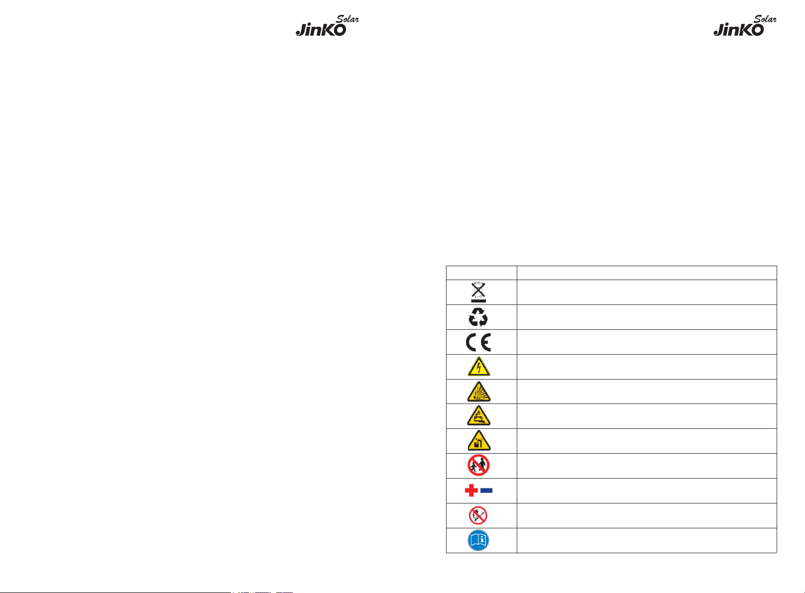
2.3 Warning Labels
Symbols
Description
Do not dispose in trash
Lithium ion battery can be recycled
Certification in European union area
Electric shock hazard
Explosive gas
Alternating Current (AC)
Heavy enough to cause severe injury
Keep the Pack away from children
Make sure the battery polarity well connected
Do not expose to fire
Operate as the Manual

6
5
Fig 2.1: Nameplate
Note: When the ambient temperature is between -10℃ and 0℃, the maximum charging
current of the battery is 2.5A.
2.4 Emergency Responses
Manufacturer takes foreseeable risk scenarios into consideration and is designed to
reduce hazards and dangers. However, if the following situation occurs, do as below:
Situation Occurs
Description and Action Need
Leakage
Avoid touch of leaking liquid or gas. If you touch the leaking
electrolyte, do as below immediately.
Inhalation: Evacuate the contaminated area, and seek medical help.
Eye contact: Rinse eyes with flowing water for 15 minutes, and seek
medical help.
Skin contact: Rinse contacted area thoroughly with soap and water,
and seek medical help.
Ingestion: Vomiting, and seek medical help.
Fire
It's hard for PACK systems ignite spontaneously. If the PACK has
caught a fire, do not try to extinguish the fire but evacuate people
immediately.
Wet Packs
If PACK is flooded or submerged, do not access it. Contact Jinko or
distributor for technical assistance immediately.
Damaged PACKS
Damaged PACKS are dangerous and must be handled with special
attention. They are no longer suitable for use and may cause danger
to people. If the PACK damaged, stop use it and then contact the
Jinko or distributor.
3 Storage and Transportation
3.1 Storage Requirements
ØPlace the PACK follow the identification on the packing case during storage.
ØDo not put the PACK upside down or sidelong.
ØThe defective PACK needs to be separated from other PACKs.
ØThe storage environment requirements are as follows:
Install the PACK in a dry and clean place with proper ventilation.
The storage temperature for a short week is between -30°C to 60℃.
If you store the PACK over a long period of six months, the storage temperature is
between-20°C to 50°C, relative humidity: 5%~95%RH.
Place the PACK away from corrosive and organic substances (including gas exposure).
Free from direct exposure to sunlight and rain .
At least two meters away from heat sources (such as a radiator).
Free from exposure to intensive infrared radiation.
Note: If a PACK is useless for six months, it needs to be recharged.
3.2 Transportation Requirement
PACK has been certified in UN38.3 (Section 38.3 of the sixth Revised Edition of the
Recommendations on the Transport of Dangerous Goods: Manual of Tests and Criteria)
and SN/T 0370.2-2009 (Part 2: Performance Test of the Rules for the Inspection of
Packaging for Exporting Dangerous Goods). PACK is classified as category 9 dangerous
goods.
ØThe PACK shall not be transported with other inflammable, explosive or toxic
substances.
ØEnsure the original Package and label complete and recognizable.
ØProhibit direct exposure to sunlight, rain, condensing water caused by temperature
difference and mechanical damages.
ØProhibit to pile up more than six PACKs.
ØThere will be a drop in capacity during transportation and storage.
ØTransportation temperature is between-20°C to 50°C, relative humidity: 5%~95%RH.
Recharge procedures
1.Identify the PACK that needs recharging.
2.Refer to quick installation guidance, complete the installation and wire connection.
Ensure PACK in off status during all the steps.
3.Set the power system as “CC=25A, CV=55.8V” , activate the PACK and start
recharging.
4.Recharge until LED2 flicks.
5.Having completed recharge, leave circuit open for five minutes before check voltage. If
voltage is not less than 52V, the recharge is successful.

78
4Installation
WARNING
ØEnsure to read the Guidance before installation in order to understand
product information and safety cautions;
ØOperators should be well trained technicians and fully understand the
whole photovoltaic system, grid network, working principle and national
regional standards;
ØInstallers must use insulating tools and wear safety equipment;
ØDevice damages caused by failure to comply with storage,
transportation, installation and use requirements specified in Guidance
are not coved by Warranty.
4.1 Installation Environment
The ambient temperature for the installation of the battery system shall be above -10℃,
below 50℃, and the humidity shall between 5% and 95%.
Max.+50℃Min.-10℃RH.+5%~+95%
Fig 4.1: Installation environment requirements
4.2 Basic Installation Requirements
ØThe PACK can be installed indoors or outdoors. The following conditions are allowed:
Fig 4.2: Acceptable wall mounted installation
Ground
Ground
Wall
Fig 4.3: Acceptable floor standing installation
Do not place the PACK upside down.
WARNING
ØBuild sun& rain shade to avoid direct exposure to the sunlight and rain.
Wall Wall
Fig 4.4: Shade for JKS-B5150-BI
4.3 Installation Required Tools
The following tools are required to install the PACK:
Drill Screw Driver Wrench
Pencil Tap Measure Multimeter
Ground
Ground Ground
Wall

10
9
4.4 Installation Procedures
It is recommended to wear the following safety gear when dealing with the PACK.
Insulated Glove Safety Goggle Safety Shoes
Pre-installation Check
Check the package
Check the PACK package before open it. If any abnormity is
detected, do not open the Package and contact your distributor.
Check the power
Check and confirm the PACK is powered off before installation.
Check deliverable
Check the quantity of all parts inside according to the package
list. If there is any part missing or damaged, please contact your
distributor.
Check the JKS-B5150-BI
Fig 4.5: Components and parts of JKS-B5150-BI
Check the Accessories
JKS-B5150-BI Cable Parallel Cable JKS-B5150-BI Base
A B CD
Installation Method
Compound Mode
Standard wall-mounted installation
A+B
Standard floor installation
A+B+D
Wall-mounted battery system stacked in two line
A+B+C
Floor installation battery system stacked in two line
A+B+C+D*2
Fig 4.6:Multiple JKS-B5150-BI installation process
Wall Mounted Installation
Step 1: Please make sure that the weight capacity of wall should exceed 150kg.
Step 2: Assemble the wall hangers together. If you want to install four packs, make four
wall hangers together. We can parallel two to ten at a time .But, it is recommended that
no more than four packs be mounted on wall.
Step 3: Place the wall hangers on the wall and mark the holes that need to be punched.
We recommend two persons participate the installation. One person places the wall
hangers on wall and ensure the gradienter horizontal; the other person marks the holes.
Each wall hanger has two fixed positions. After mark the holes, put down the wall
hangers.
Step 4: Drill a hole at the marked point with a depth of 55mm at the mark with a drill of
φ8.Expand the bolt with a hammer into the hole in the wall , install the nut(including
elastic flat pad)and tighten the nut with a wrench.
Step 5: Hang the JKS-B5150-BI on the wall hangers. Adjust the battery level with M6
external hexagon torque wrench and install the safety screws (M4x10 Combination
screw) on both sides of all modules.
Step 6: Plug the connected power lines into PACK terminals (red positive terminal and
black negative terminal). Plug the well-connected CAN communication line into the
communication ports of PCS and PACK.
Note: The number of wall-mount installations should not exceed four.
Adjust the screw to ensure the
battery in horizontal position
1
JKS-B5150-BI Wall hangers×1 Parallel communication line ×1
Ground wire ×1
Positive parallel power line ×1
Negative parallel power line ×1
Quick installation manual ×1
Operation manual ×1
Warranty card ×1
Certification ×1
Certification
Warranty card
Quick installation
manual
Operation manual
M6 Explosive screw ×2
M6 Flange nut ×1
M4×10Combinationscrew ×2

Floor Standing Installation
Step 1: Assemble the wall hangers together. If you want to install four packs, make four
wall hangers together. We can parallel two to ten at a time . We recommend that the
stack number be no higher than six. However, if necessary our structure allows us to
stack higher.
Step 2: Place the mount base where you want the PACK to be mounted. Put the wall
hangers on the wall and match the base.
Step 3: Mark the holes that need to be punched. We recommend two persons participate
the installation.One person places the wall hangers on wall and ensure the gradienter
horizontal; the other person marks the holes. Noted that only two ends of the top wall
hanger and the bottom wall hanger need to be marked.. After mark the holes, put down
the wall hangers.
Step 4: Drill a hole at the marked point with a depth of 55mm at the mark with a drill of
φ8. Expand the bolt with a hammer into the hole in the wall , install the nut(including
elastic flat pad)and tighten the nut with a wrench.
Step 5: Hang the JKS-B5150-BI on the wall hangers. Adjust the battery level with M6
external hexagon torque wrench and install the safety screws (M4x10 Combination
screw) on both sides of all modules.
Step 6: Plug the connected power lines into PACK terminals (red positive terminal and
black negative terminal). Plug the well-connected CAN communication line into the
communication ports of PCS and PACK.
Note:If more than 4 batteries are used, base mounting is recommended.
For floor installation, we recommend that the number of the stacked battery modules is
no higher than six.
Fig 4.7:Multiple JKS-B5150-BI with base installation process
4.5 Electrical Connection
Do not forget wear ESD wrist strap and gloves, safety gloves and
goggles.
WARNING
Terminal Definition:
Fig 4.8: Terminal definition
11
Serial
Number
Item
Quantity
Specifications
Symbol
1
Communication Port
1
IP67 Rj45 water proof connector
PCS
2
Communication Port
1
IP67 Rj45 water proof connector
LINK-IN
3
Communication Port
1
IP67 Rj45 water proof connector
LINK-
OUT
4
Safety Vent
1
Pressures inside released via the
vent
PCS
5
Negative Terminal
2
IP67–Black connector
BAT-
6
Grounding Terminal
2
M6 Screw
7
Positive Terminal
2
IP67–Red connector
BAT+
8
USB Interface
1
USB interface for Program
Upgrade
BAT-
9
LED Indicator
1
Five leds
BAT+
10
POWER Button
1
IP67–Button to turn on or off the
PACK
POWER
11
Circuit Breaker
1
Turn on or turn off the Battery
output
11 12

13 14
RS485&CAN Crystal Plug Definition:
Item
Crystal Head Picture
Serial No.
Definition
PCS
1
RS485_B
2
RS 485_A
3
GND_COM
4
CANH
5
CANL
6
GND_COM
7
WAKE-
8
WAKE+
Communication Interface Definition:
Fig 4.9: System connection diagram Fig 4.10: Parallel connection stacked in two line
4.5.1 System Connection Diagram
Note:
The battery is not allowed to be installed in the running state, and all the RUN lights of
battery modules should be off before installation.
To ensure system security, do not forget to install ground wire.
For the power lines connected to PCS, the positive power line is drawn from the top
battery module, and the negative power line is drawn from the bottom battery module .
The breaker between PCS and JKS, we recommend to use molded case circuit breaker
with rated working voltage greater than 80V and rated working current greater than
125A.
4.5.2 System Connection Diagram of Two Line
When stacked in two lines, you need to buy the accessory of wires connecting two stacks
of battery systems. The connection mode is shown in the figure 13.
4.5.3 Electrical Wiring Connection
1. When the power wiring harness is connected, please pay attention to the positive and
negative terminals, the red terminals are connected to the positive terminals and the
black terminals to the negative terminals.
2. PE conductor is used to connect between PACKs,with a cross-sectional area of
5.2mm².
The PCS communication terminal is used to communicate to the PCS. Link-in terminals
are used for signal inlet of multiple parallel battery packs. Link-out terminals are used for
signal output of multiple parallel battery packs.
4.5.4 Power Line Connection
Press the position indicated in the figure above before disconnecting the power terminal.
Fig 4.11: Connect and disconnect power terminals
4.5.5 Communication Line Connection
Fig 4.12: Connect and disconnect communication terminals
1.Parallel communication is the connection between the middle communication plug of
the first module and the lower communication plug of the next module.
2.The uppermost communication plug of the top battery module is connected to the
PCS.
JKS-B5150-BI Parallel Cable
JKS-B5150-BI
Cable

15 16
5Power On and Off the Battery
5.1 Power On
Power on the PACK by Pressing Power Button(t>2S)
Serial
Procedures
Acceptation Criteria
1
Connect the battery and PCS.
Make sure the wiring harnesses are well
connected.
2
Close the breaker of the PACK.
Make sure the breaker is ON.
3
Press POWER button for three to
eight seconds. Observe the LED
indication on panel.
1. If both RUN/ALM and SOC lights turn on
normally, PACK is powered on successfully.
2. If RUN/ALM light turns red, there is a
failure and should solve it before power on
again.
WARNING
ØThe installation and use of batteries involve much specialized
knowledge. Therefore, technicians should be given appropriate technical
training and obtain operational certificates in compliance with local laws
and regulations. Please ensure technicians have obtained training
certificate before operation.
ØPlease stand on dry insulating objects and do not wear conductive
material such as watches and necklace during operation. Insulated tools
should be used.
ØDo not contact any positions with potential difference.
ØProhibition sign should be hung on the battery:”Non - professionals,
do not touch”.
ØIf any abnormalities occur during the startup phase, power off the
PACK immediately. After problem confirmed, proceed again.
ØMake sure the inverter is turned off before checking the PACK.
Power ON battery system
5.2 Power Off
Press the power button to turn off the PACK and five LED lights will flicker for three
times. If under the situation of multiple packs in parallel, only turning off one of the
packs then the whole battery system will turn off.
Turn the circuit breaker to the “ON”
position.Press the power button for 3
seconds to turn on the battery.The battery
LED indicator lights up to indicate that the
battery has been turned on.
Power OFF battery system
Turn the circuit breaker to the “OFF”
position.Press the power button to turn
off the battery.The battery LED indicator
is off,and the battery has been turned
off.
Power on the PACK by PCS
1
Connect the battery and PCS.
Make sure the wiring harnesses are well
connected.
2
Close the breaker of the PACK.
Make sure the breaker is ON.
3
Power on the PCS. PCS outputs
a wake up signal of 5V or an
output main circuit voltage
signal of 46-58V.
1. If both RUN/ALM and SOC lights turn on
normal, PACK powers on successfully.
2. If RUN/ALM light turns red, there is a
failure and should solve it before power on
again.

6 Maintenance Guide
6.1 Preparation
ØTools like safety gloves, cross head driver and socket wrench should be prepared.
ØTurn off and turn on new PACK.
1. If the PACK is power-off. Press power button for 3-8 seconds to turn on.
2. If the PACK is power-on. Press power button once to turn off.
Before maintaining the battery, turn off the breaker and press power button once to
make sure the PACK is in the power-off mode. Follow the installation and wire
connection procedures specified above. Ensure wires are properly connected before turn
the breaker on. After that, turn on the breaker and press power button of any PACK for
3-8 seconds to check if the system normal works.
6.2 PACK Replacement
§Wear safety gloves.
§Close the breaker and power off the PACK.
§Disconnect power lines and CAN communication lines of the PACK.
§Wall-mounting PACK: Uninstall the safety screws on both sides of the PACK. Lift up the
PACK.
§Floor-standing PACK: Uninstall the safety part and open the connector at both ends of
the battery of the batteries. Lift up the PACK.
§Put the PACK into the packing box according to the repair procedure and transport the
PACK to the designated repair site.
§Install new PACK based on procedure specified in Section 4.
6.3 System Failure Information List and Troubleshooting
Suggestions
Error
Indication
Error
Description
Error Cause
Suggested Actions
ALM
(ALM
Light
Flickers)
Discharge under
voltage
protection
Single cell voltage
below the threshold
for under-voltage
protection.
There is over discharge risk. User
should stop discharging and
arrange recharge.
Charge over
voltage
protection
Single cell voltage
exceeding
threshold for
protection
threshold.
1. There is no safety threat.
2. User should stop charging.Idle
PACK and it will turn to normal
status.
External CAN
communication
failure
Communication loss
between
PCS and PACK.
1. There is no safety threat and
user should stop using battery.
2. Check if PCS and Battery
communication terminal is well
connected.
3. If PCS and PACK cannot
communicate when the
communication wire is
confirmed well connected, user
should contact installer to repair
Battery.
Interior CAN
communication
failure
Communication loss
between
two parallel.
1. Check CAN connection
between two Batteries, CAN
connection between Linkin and
Linkout;
Parallel
connection
failure
protection
Communication
failure between two
parallel connected
PACK.
1. Check CAN connection
between two batteries, CAN
connection between Battery and
PCS;
(ALM
Light On)
Discharge short
circuit
External short circuit
of PACK.
There is safety risk and user
should stop using Battery.
User should contact installer to
repair PCS and Battery.
Precharger short
circuit
Precharger
overtime circuit
Type
inconsistency of
PACK
The pack type is
different.
There is safety risk and user
should stop using battery.
User should contact installer to
use the same PACK in Parallel.
Main circuit fault
BMS main power
circuit failure.
There is safety risk and user
should stop using Battery.
User should contact installer to
repair Battery.
17 18

19 20
7 Technical Specifications
Functional parameters of JKS-B5150-BI energy storage system are as shown below:
No.
Items
Specification
1
Battery Module
JKS-B5150-BI (2.56kWh, 51.2V, 28kg)
2
Nominal/Rated Capacity
50Ah/45Ah
3
Nominal/Rated Energy
2560Wh/2300Wh
4
Nominal Voltage
51.2V
5
Operating Voltage
47.2-56.8V
6
Rated Current
25A
7
Battery Type
Cobalt Free Lithium Iron Phosphate (LFP)
8
Operative Temperature Range
-10~50℃
9
Recommended Operating
0℃~30℃
10
Storage Conditions
Temperature: -10°C ~ + 50°C
Humidity:5%~95%RH
Within six months after initial charge
11
Cooling
Natural cooling
12
Dimension (W/D/H)
650/260/185mm
13
Weight
28kg
14
Installation
Wall-mounted installation/floor standing
installation
15
Ingress Protection
IP65
16
Cell Safety Certification
IEC62619/UL1642
17
PACK Safety Certification
IEC62619/IEC62040/CE/RCM/ CEC
18
UN Transportation Test Standard
UN38.3
19
Communication Port
CAN/RS485(Optional)
20
Parallel Connection
Two-Ten PACKs
21
Maximum Current For Multiple
Parallel Machines To PCS
100A
LED Light Definition
Status
Items
SOC Indication
RUN/ALM
Remark
LED1
LED2
LED3
LED4
LED5
Charge
SOC
0%-25%
(t=1S)
RUN/ALM light
on and one
SOC lights
flicker
26%-50%
(t=1S)
51%-75%
(t=1S)
76%-99%
(t=1S)
100%
Discharge
SOC
100%-76%
75%-51%
50%-26%
25%-5%
5%-0%
(t=1S)
RUN/ALM light
flicker
Idle
100%-76%
75%-51%
50%-26%
25%-5%
5%-0%
(t=1S)
RUN/ALM light
flicker
Parallel
Connection
Parallel
connection
succeeds
RUN/ALM light
flicker green
Protection
Cell charge
overvoltage
alarm
LED1-LED4 indicates current
remaining capacity
(t=1S)
RUN/ALM light
flicker green
Cell charge
overvoltage
protection
(t=1S)
RUN/ALM light
flicker green
PACK
charge
overvoltage
alarm
(t=1S)
RUN/ALM light
flicker green
PACK
charge
overvoltage
protection
(t=1S)
RUN/ALM light
flicker green
Over charge
and over
discharge
alarm
(t=1S)
RUN/ALM light
flicker green
Appendix I
7.1 LED Indication Control Mechanism

22
21
Over charge
and over
discharge
protection
(t=1S)
RUN/ALM light
flicker green
Charging
current limit
does not
respond
(t=1S)
RUN/ALM light
flicker green
Charge and
discharge high
temperature
alarm
(t=1S)
RUN/ALM light
flicker green
Charge and
discharge high
temperature
protection
(t=1S)
RUN/ALM light
flicker green
Charge and
discharge low
temperature
alarm
(t=1S)
RUN/ALM light
flicker green
Charge and
discharge low
temperature
protection
(t=1S)
RUN/ALM light
flicker green
Cell discharge
undervoltage
alarm
(t=1S)
RUN/ALM light
flicker green
Cell discharge
undervoltage
protection
(t=1S)
RUN/ALM light
flicker green
PACK
discharge
undervoltage
alarm
(t=1S)
RUN/ALM light
flicker green
PACK
discharge
undervoltage
protection
(t=1S)
RUN/ALM light
flicker green
Charge and
discharge
Overcurrent
hardware
protection
(t=1S)
RUN/ALM light
flicker green
Mos high
temperature
alarm
(t=1S)
RUN/ALM light
flicker green
Mos high
temperature
protection
(t=1S)
RUN/ALM light
flicker green
High
temperature
environment
alarm
(t=1S)
RUN/ALM light
flicker green
High
temperature
environment
protection
(t=1S)
RUN/ALM light
flicker green
Cell Large
voltage
difference
alarm
(t=1S)
RUN/ALM light
flicker green
Cell Large
voltage
difference
protection
(t=1S)
RUN/ALM light
flicker green
difference
protection
between PACK
voltage and
module voltage
(t=1S)
RUN/ALM light
flicker green
Parallel
connection
over charge and
over discharge
alarm
(t=1S)
RUN/ALM light
flicker green
Fault,
personnel
handling
required
Discharge short
circuit
LED1-LED4 indicates current
remaining capacity
(t=1S)
RUN/ALM light
flicker red
Precharged
short circuit
(t=1S)
RUN/ALM light
flicker red
Precharged
overtime circuit
(t=1S)
RUN/ALM light
flicker red
External CAN
communication
failure
(t=1S)
RUN/ALM light
flicker red
Interior CAN
communication
failure
(t=1S)
RUN/ALM light
flicker red
Parallel
connection
failure
(t=1S)
RUN/ALM light
flicker red

23
Type
inconsistenc
y of PACK
(t=1S)
RUN/ALM light
flicker red
Batteries
failure
protection
RUN/ALM light
stays red
Voltage
sampling
anomaly
protection
RUN/ALM light
stays red
Current
sampling
fault
RUN/ALM light
stays red
Main circuit
fault
RUN/ALM light
stays red
IFpP41/150/102/[1P16S]M/-10+50/90
Method for calculating rated capacity:
Rated capacity of the measured module: 45 Ah
Number of modules connected in parallel: 10
Calculated rated capacity (Ah) = 45 Ah×N = 45*N Ah (N=1~10)
Recommend charging method declared by the manufacturer:
1.Constant current 25A charging to 54V;
2.Constant current 10A charging to 55V;
3.Constant current 2A charging to 55V;
7.2 Product Description
General product information and other remarks:
Product Description:
The models JKS-B5150-BI , JKS-B51100-BI , JKS-B51150-BI, JKS-B51200-BI, JKS-B51250-
BI, JKS-B51300-BI, JKS-B51350-BI, JKS-B51400-BI, JKS-B51450-BI, JKS-B51500-BI is
composed of JKS-B5150-BI 2-10 in parallel.JKS-B5150-BI is an energy storage unit
composed of electrochemical cells, switch button, battery management system (BMS),
power and signal terminals, and mechanical parts. Each JKS-B5150-BI consists of 50Ah
cells which form 51.2V voltage battery pack via one parallel and sixteen serial connection
(1P16S). In the final installation, all models only be connected to the DVC A circuit.
Model Difference:
The models JKS-B5150-BI, JKS-B51100-BI, JKS-B51150-BI, JKS-B51200-BI, JKS-B51250-
BI, JKS-B51300-BI, JKS-B51350-BI, JKS-B51400-BI, JKS-B51450-BI, JKS-B51500-BI are
same as the construction, hardware and software, excepted the parallel number of
battery systems as below table.
Produce Name
Lithium Ion Battery
Model
JKS-B5150-BI
Rated Capacity (Ah)
45
Rated Energy (kWh)
2.3
Operating Voltage
51.2
Rated Charge Current (A)
25
Rated Discharge Current (A)
25
Maximum Charge Current (A)
48
Maximum Discharge Current (A)
48
Operating Ambient Temperature
-10 °C ~ 50 °C
Storage Temperature
- 30°C ~50°C / 7 days; - 20°C ~45°C / 6
months; 95%RH
Rated Charge Voltage (V)
55
Maximum Charge Voltage (V)
56.8
End-of-Discharge Voltage (V)
47.2
Dimension
W/D/H: 650 / 260 / 185 mm
Weight (kg)
28±2
Pack Pattern
1P16S
Recommend Charging Method Declared
by The Manufacturer
1.Constant current 25A charging to 54V;
2.Constant current 10A charging to 55V;
3.Constant current 2A charging to 55V;
Overcharge Voltage Protection
3.7V/Cell
Over Current Protection
49
Thermal Protection
55°C /Cell
24
Model
Difference
JKS-
B5150-BI
JKS-
B51100-BI
JKS-
B51150-BI
JKS-
B51200-BI
JKS-
B51250-BI
Parallel
Number of
Module
1 2 3 4 5
Model
Difference
JKS-
B51300-BI
JKS-
B51350-BI
JKS-
B51400-BI
JKS-
B51450-BI
JKS-
B51500-BI
Parallel
Number of
Module
6 7 8 9 10

25 26
Battery System
Model Name JKS-B51100-BI JKS-B51150-BI JKS-B51200-BI
Rated Capacity(Ah) 90 135 180
Rated Energy(kWh) 4.6 6.9 9.2
Parallel Number of
Module 2 3 4
Nominal Voltage (V) 51.2
Standard Charge
Current (A)
Standard Discharge
Current (A)
Maximum Charge
Current (A)
Maximum Discharge
Current (A)
Charge Temperature
Range -10 °C ~ 50 °C
Discharge
Temperature Range -10 °C ~ 50 °C
Storage Temperature - 30°C ~50°C / 7 days;
- 20°C ~45°C / 6 months; 95%RH
Standard Charge
Voltage 55V
Maximum Charge
Voltage 56.8V
Discharge Cut off
Voltage 47.2V
Size(width/depth/hei
ght) (mm) 650*260*366 650*260*547 650*260*728
Weight (kg) 56 84 112
Pack Pattern (1P16S)2P (1P16S)3P (1P16S)4P
Battery Designation
IFpP/41/150/102/[
(1P16S)2P]M/-
10+50/90
IFpP/41/150/102/[
(1P16S)3P]M/-
10+50/90
IFpP/41/150/102/[
(1P16S)4P]M/-
10+50/90
Recommend
Charging Method
Declared by The
Manufacturer
Overcharge Voltage
Protection 3.7V/Cell
Over Current
Protection
Thermal Protection
110A
55°C /Cell
1.Constant
current 50A
charging to 54V;
2.Constant
current 10A
charging to 55V;
3.Constant
current 2A
charging to 55V;
50 75 100
50 75 100
96 110 110
96 110 110
98A
1.Constant
current 75A
charging to 54V;
2.Constant
current 10A
charging to 55V;
3.Constant
current 2A
charging to 55V;
1.Constant
current 100A
charging to 54V;
2.Constant
current 10A
charging to 55V;
3.Constant
current 2A
charging to 55V;

Battery System
Model Name
JKS-B51250-BI
JKS-B51300-BI
JKS-B51350-BI
Rated Capacity(Ah)
225
270
315
Rated Energy(kWh)
11.5
13.8
16.1
Parallel Number of
Module
5
6
7
Nominal Voltage (V)
51.2
Standard Charge
Current (A)
100
Standard Discharge
Current (A)
100
Maximum Charge
Current (A)
110
Maximum Discharge
Current (A)
110
Charge Temperature
Range
-10 °C ~ 50 °C
Discharge
Temperature Range
-10 °C ~ 50 °C
Storage Temperature
- 30°C ~50°C / 7 days;
- 20°C ~45°C / 6 months; 95%RH
Standard Charge
Voltage
55V
Maximum Charge
Voltage
56.8V
Discharge Cut off
Voltage
47.2V
Size(width/depth/hei
ght) (mm)
650*260*909
650*260*1090
650*260*1271
Weight (kg) 140 168 196
Pack Pattern (1P16S)5P (1P16S)6P (1P16S)7P
Battery Designation
IFpP/41/150/102/[
(1P16S)5P]M/-
10+50/90
IFpP/41/150/102/[
(1P16S)6P]M/-
10+50/90
IFpP/41/150/102/[
(1P16S)7P]M/-
10+50/90
Recommend
Charging Method
Declared by The
Manufacturer
Overcharge Voltage
Protection 3.7V/Cell
Over Current
Protection
Thermal Protection
110A
55°C /Cell
1.Constant current 100A charging to 54V;
2.Constant current 10A charging to 55V;
3.Constant current 2A charging to 55V;
27 28

Battery System
Model Name
JKS-B51400-BI
JKS-B51450-BI
JKS-B51500-BI
Rated Capacity(Ah)
360
405
450
Rated Energy(kWh)
18.4
20.7
23
Parallel Number of
Module
8
9
10
Nominal Voltage (V)
51.2
Standard Charge
Current (A)
100
Standard Discharge
Current (A)
100
Maximum Charge
Current (A)
110
Maximum Discharge
Current (A)
110
Charge Temperature
Range
-10 °C ~ 50 °C
Discharge
Temperature Range
-10 °C ~ 50 °C
Storage Temperature
- 30°C ~50°C / 7 days;
- 20°C ~45°C / 6 months; 95%RH
Standard Charge
Voltage
55V
Maximum Charge
Voltage
56.8V
Discharge Cut off
Voltage
47.2V
Size(width/depth/hei
ght) (mm)
650*260*1452
650*260*1633
650*260*1814
Weight (kg) 224 252 280
Pack Pattern (1P16S)8P (1P16S)9P (1P16S)10P
Battery Designation
IFpP/41/150/102/[
(1P16S)8P]M/-
10+50/90
IFpP/41/150/102/[
(1P16S)9P]M/-
10+50/90
IFpP/41/150/102/[
(1P16S)10P]M/-
10+50/90
Recommend
Charging Method
Declared by The
Manufacturer
Overcharge Voltage
Protection 3.7V/Cell
Over Current
Protection
Thermal Protection
110A
55°C /Cell
1.Constant current 100A charging to 54V;
2.Constant current 10A charging to 55V;
3.Constant current 2A charging to 55V;
29 30
Table of contents
Other Jinko Solar Camera Accessories manuals