Page 7 • JL Audio, Inc., 2015
MID/HIGH FREQUENCY DRIVER FITMENT
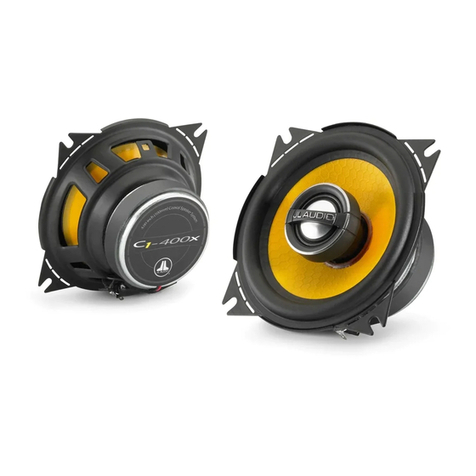
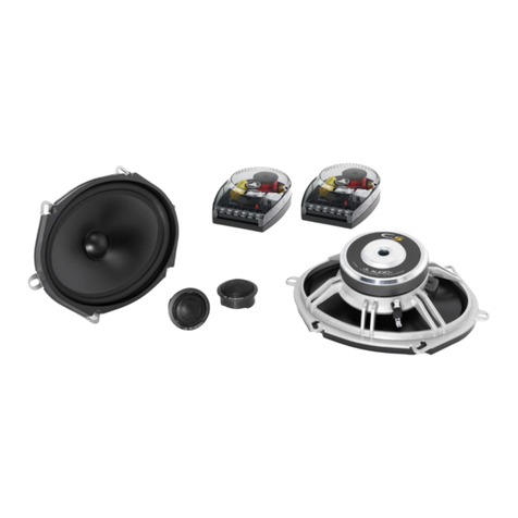
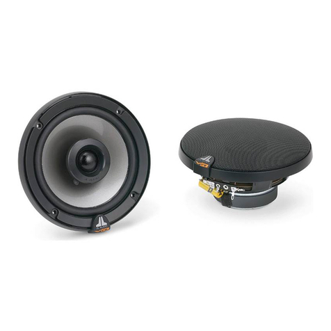
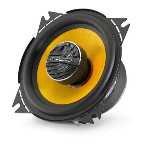
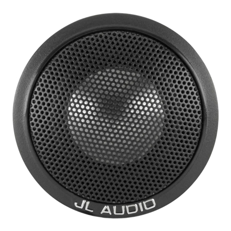
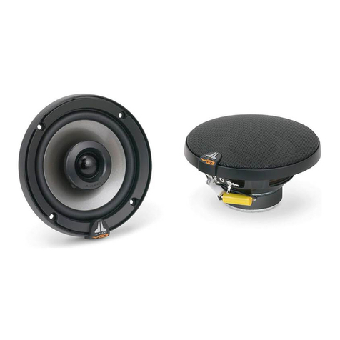
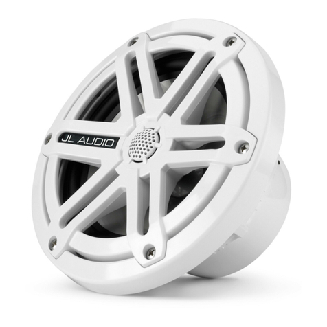
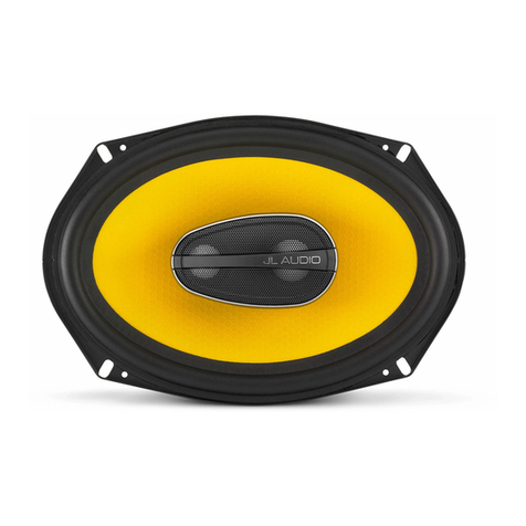
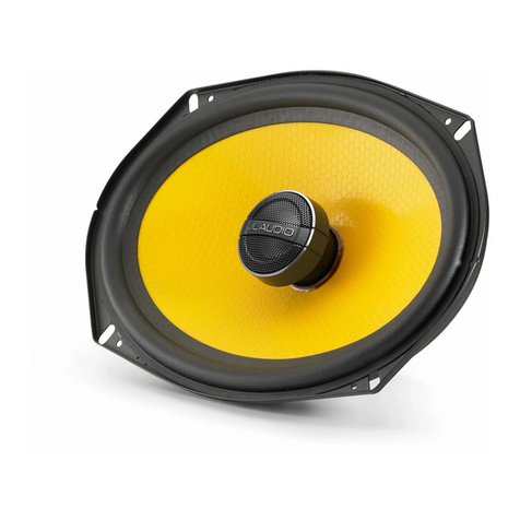
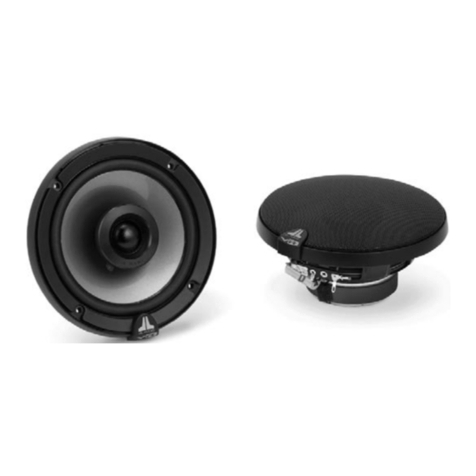
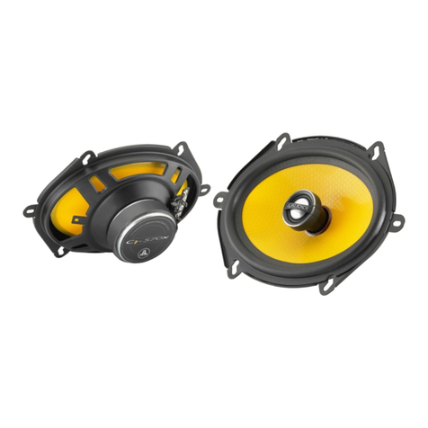
A variety of JL Audio coaxial and component systems will t in the factory speaker locations of you vehicle.
Front Speaker Size / Location: 6-1/2”- Front Doors
Fits JL Audio Models: TR650-CXi, TR650-CSi, C2-650x, C2-650,
C3-650, C5-650x, C5-650, & ZR650-CSi
Rear Speaker Size / Location: 6-1/2”- Rear Door
Fits JL Audio Models: TR650-CXi, TR650-CSi, C2-650x, C2-650,
C3-650, C5-650x, C5-650, & ZR650-CSi
All specifications are subject to change without notice. “JL Audio®”and the JL Audio logo, and “Stealthbox” and the Stealthbox logo are registered trademarks of JL Audio, Inc.,. “Ahead of the
Curve”, its respective logo, and“How we play” are trademarks of JL Audio, Inc.,.
Printed in USA • ©2013 JL Audio, Inc.,. • U.S. PATENTS: #5,734,734 #5,949,898 #6,118,884 #6,229,902 #6,243,479 #6,294,959 #6,501,844 #6,496,590 #6,441,685 #5,687,247 #6,219,431
#6,625,292 #D472,891 #D480,709 Other U.S. & Foreign patents pending. For more detailed information please visit us online at www.jlaudio.com.
(954) 443-1100
www.jlaudio.com
JLA-SKU# 011432 • ver. 05.12.2015 • 10369 NORTH COMMERCE PARKWAY • MIRAMAR, FLORIDA • 33025 • USA
CONGRATULATIONS!
You have completed the installation for this model! Enjoy your new Stealthbox®!
How we play.™
SB-F-MUSCPE/12TW3 INSTR_SKU# 011432
STEP 28
Note: Step 28 is only necessary in
vehicles equipped with the factory
subwoofer.
Apply Velcro to the bottom of the trim panel as
shown, and secure it to the trunk floor in front
of the Stealthbox®.
STEP 27
Reinstall the subwoofer. Reinstall the trunk
liner clip above the Stealthbox®. Reinstall the
trunk sill panel, cargo net hooks, and trunk
floor panel.
STEP 26
Slide a 3/8” x 1-1/4” Fender Washer, a 3/8” Flat
Washer, a 3/8” Lock Washer, and a 3/8 - 16 Nut
over the 3/8 - 16 x 2-1/2” Set Screw at the back
of the enclosure.
Slide an M8 - 24 mm Washer, an M8 - 16 mm
Washer, an M8 Lock Washer, and an M8 - 1.25
mm Nut over each of the M8 - 70 mm Set
Screws at the bottom of the enclosure.
Tighten all hardware.
STEP 25
Guide the enclosure into position, aligning the
two holes in the bottom of the enclosure with
the two M8 - 70 mm Set Screws.
Back out the two M8 - 70 mm Set Screws,
allowing them to pass through the holes in the
bottom of the enclosure, until approximately
3/4” is exposed.


