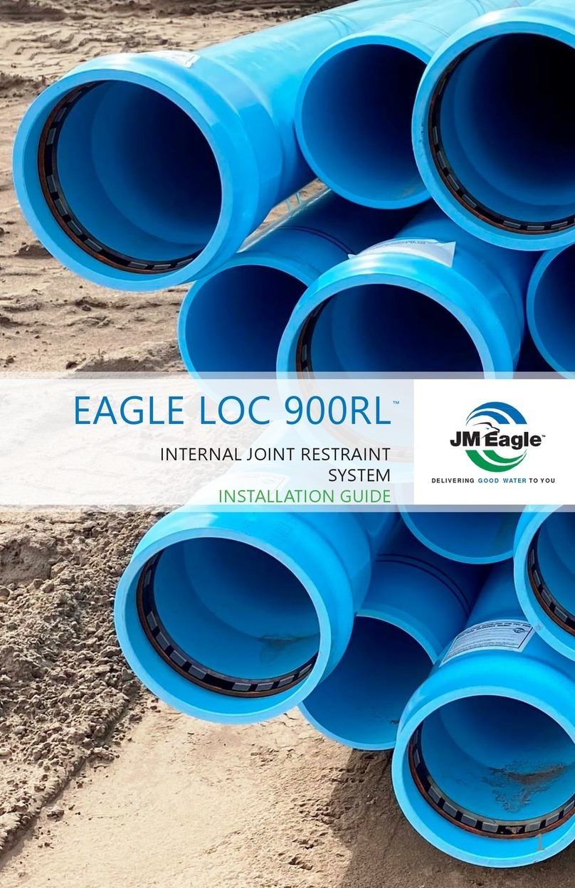
JM Eagle EAGLE LOC 900 User manual

DELIVERING GOOD WATER TO YOU
EAGLE LOC 900™
INTERNAL JOINT RESTRAINT SYSTEM
INSTALLATION GUIDE


ASSEMBLY INSTRUCTIONS . . . . . . . . . . . . . . . . . . . . . . . . . . . . . . . . . . .
INTRODUCTION . . . . . . . . . . . . . . . . . . . . . . . . . . . . . . . . . . . . . . . . . .
INSPECT EAGLE LOC HARDWARE
CLEAN
INSTALL THE INSERTION STOP . . . . . . . . . . . . . . . . . . . . . . . . . . . . . .
LUBRICATE . . . . . . . . . . . . . . . . . . . . . . . . . . . . . . . . . . . . . . . . . . . . .
ALIGN AND ASSEMBLE
PREVENT OVER ASSEMBLY
COLD WEATHER INSTALLATION OF EAGLE LOC 900. . . . . . . . . . . . . . .
SAFE PULLING FORCE FOR HDD . . . . . . . . . . . . . . . . . . . . . . . . . . . . . .
CONTENTS
EAGLE LOC 900™
1.0
1.1
1.2
1.3
1.4
1.5
1.6
1.7
2.0
3.0
6
6
6
7
9
10
10
11
15
16

4EAGLE LOC 900™INSTALLATION GUIDE
WARRANTY
J-M Manufacturing Company Inc. (JM Eagle™) warrants that its standard
polyvinyl chloride (PVC), polyethylene (PE), conduit/plumbing/solvent weld
and Acrylonitrile-Butadiene-Styrene (ABS) pipe products (“Products”)
are manufactured in accordance with applicable industry specifications
referenced on the Product and are free from defects in workmanship
and materials. Every claim under this warranty shall be void unless in
writing and received by JM Eagle™within 30 days of the date the defect
was discovered, and within one year of the date of shipment from the
JM Eagle™plant. Claims for Product appearance defects, such as sun-
bleached pipe etc., however, must be made within 30 days of the date of
the shipment from the JM Eagle™plant. This warranty specifically excludes
any Products allowed to become sun-bleached after shipment from the
JM Eagle™plant. Proof of purchase with the date thereof must be presented to
the satisfaction of JM Eagle™, with any claim made pursuant to this warranty.
JM Eagle™must first be given an opportunity to inspect the alleged defective
Products in order to determine if it meets applicable industry standards, if the
handling and installation have been satisfactorily performed in accordance
with JM Eagle™recommended practices and if operating conditions are
within standards. Written permission and/or a Return Goods Authorization
(RGA) must be obtained along with instructions for return shipment to JM
Eagle™of any Products claimed to be defective.
The limited and exclusive remedy for breach of this Limited Warranty shall
be, at JM Eagle’s sole discretion, the replacement of the same type, size
and like quantity of non-defective Product, or credits, offsets or combination
of thereof, for the wholesale purchase price of the defective unit.
This Limited Warranty does not apply for any Product failures caused
by user’s flawed designs or specifications, unsatisfactory applications,
improper installations, use in conjunction with incompatible materials,
contact with aggressive chemical agents, freezing or overheating of liquids
in the Product, and any other misuse causes not listed here. This Limited
Warranty also excludes failure or damage caused by fire stopping materials,
tread sealants, plasticized vinyl products or damage caused by the fault or
negligence of anyone other than JM Eagle™, or any other act or event beyond
the control of JM Eagle™.

5
EAGLE LOC 900™INSTALLATION GUIDE
JM Eagle’s liability shall not, at any time, exceed the actual wholesale
purchase price of the Product. The warranties in this document are the
only warranties applicable to the Product and there are no other warranties,
expressed or implied. This Limited Warranty specifically excludes any
liability for general damages, consequential or incidental damages,
including without limitation, costs incurred from removal, reinstallation,
or other expenses resulting from any defect. IMPLIED WARRANTIES OF
MERCHANTABILITY OR FITNESS FOR A PARTICULAR PURPOSE ARE
SPECIFICALLY DISCLAIMED AND JM Eagle™SHALL NOT BE LIABLE IN
THIS RESPECT NOTWITHSTANDING JM Eagle’s ACTUAL KNOWLEDGE
THE PRODUCT’S INTENDED USE.
JM Eagle’s Products should be used in accordance with standards set
forth by local plumbing and building laws, codes or regulations and the
applicable standards. Failure to adhere to these standards shall void this
Limited Warranty. Products sold by JM Eagle™that are manufactured by
others are warranted only to the extent and limits of the warranty of the
manufacturer. No statement, conduct or description by JM Eagle™or its
representative, in addition to or beyond this Limited Warranty, shall constitute
a warranty. This Limited Warranty may only be modified in writing signed by
an officer of JM Eagle™.

6
The Eagle Loc 900™ Installation Guide is a supplement to the Blue Brute™ Installation Guide.
1.0 ASSEMBLY INSTRUCTIONS
1.1 INTRODUCTION
Proper assembly of Eagle Loc 900 requires:
•A clean bell and spigot
•Inspecting the Eagle Loc Hardware
•Installing the Insertion Stop on the spigot (Required)
•A pplication of the recommended lubricant (a container of lubricant is
typically provided with each shipment of pipe)
•Maintenance of straight alignment during assembly
•In serting the spigot into the bell until the reference mark is even with
the lip of the bell
EAGLE LOC 900™ INSTALLATION GUIDE
1.2 CLEAN
As with conventional bell-and-spigot pipe, the gasket and the groove area
behind it should be wiped clean. If mud, dirt, silt, or other foreign material is in
the sealing area, it may prevent the gasket from sealing against the spigot. In
addition to cleaning the gasket area, the restraint hardware needs to be clean.
Debris in this area may prevent the hardware from engaging and keep the
restraint mechanism from activating.
Figure 1:The sand andgrit shown above must becleaned fromthe restraint hardware.
Dirty hardware may prevent the restraint mechanism fromworking.

7
Figure 3
Occasionally, the grip ring may have a gap that is too small. The picture to
the right in Figure 3 shows a grip ring with an excessively narrow gap and
demonstrates how the grip ring sits too low at the 3:00 o’clock
position. (Note: The grip ring was wedged to a much smaller diameter
with steel shims. The situation was greatly exaggerated to better illustrate
the point.)
To make an easy installation even simpler, the product comes supplied
with end plugs. The end plugs make it easier to keep the bell, gasket area, and
restraint hardware clean. The plugs should be left in place as long as
possible. Remove them just prior to assembling the joint.
Figure 2: The end plugs in these pipes keep dirt and other foreign material out of the bell.
1.3 INSPECT EAGLE LOC HARDWARE
There are a few items to check that are unique to Eagle Loc. Checking these
items prior to assembly will help ensure that the job goes smoothly. The grip
ring and casing should be clean with the ring teeth pointed toward the back of
the bell. The grip ring should sit at the back of the casing and be easy to rotate
inside the casing.
EAGLE LOC 900™ INSTALLATION GUIDE

8
In Figure 3, the grip ring may become cocked inside the casing when it
comes in contact with the spigot during assembly. If this occurs, assembly
forces increase dramatically.
If the gap in the grip ring is too narrow, the grip ring should be removed from
the casing. Then, the gap can be increased by manually springing the ring
apart as shown in Figure 4. Thick gloves are recommended as the teeth on the
grip ring are quite sharp. Once the gap has been increased, re-install the grip
ring in the casing.
Figure 4
Note, when re-installing the grip ring, the grip ring should be oriented such
that the tapered end of the grip ring matches the tapered end of the casing
pocket. If the grip ring is installed backwards, it will not be able to be
rotated easily inside the casing. Moreover, it will not be possible to make the
joint.
EAGLE LOC 900™INSTALLATION GUIDE

9
1.4 INSTALL THE INSERTION STOP (REQUIRED)
The Eagle Insertion Stop will greatly reduce the possibility of over insertion of
the spigot into the bell when assembling PVC pipe.
Figure 5: JM Eagle Insertion Stop
EAGLE LOC 900™INSTALLATION GUIDE

10
Ensure that the spigot is clean removing all dirt, dust, water, pipe lubrication,
etc. Eagle Loc 900 comes with two assembly mark lines on the spigot end of
the pipe. These dual lines indicate the maximum and minimum depth of
insertion of the spigot into the bell. The Insertion Stop should be placed
centered on top of the assembly line furthest from the spigot (Ex. Dashed red
line below).
EAGLE LOC 900™INSTALLATION GUIDE
Figure 6:JMEagle Insertion Stop Location
1.5 LUBRICATE
The lubricating technique is different from standard C900 pipe. Prior to
assembly, apply lube to the gasket only (Do not apply lube to the spigot or grip
ring. After applying lube to the gasket, inspect the grip ring to ensure it is free
of lube. Wipe any lube from the grip ring). Use only lubricant supplied or
recommended by JM Eagle.
1.6 ALIGN AND ASSEMBLE
Deflection is not allowed at the joint. Straight alignment is a key element for
proper assembly. Misaligned pipe greatly increases the assembly force
required to make the joint. This is especially true for Eagle Loc 900 due to
the hardware in the bell of the pipe. When properly aligned, the pipe joint
can be assembled manually using a pry bar.
EAGLE LOC 900™ INSTALLATION GUIDE

11
Figure 7: Example of an Eagle Loc joint assembly
To assemble, slide the spigot into the bell, maintaining straight
alignment, until the bell contacts the insertion stop. Do not push the
spigot farther into the bell as this reduces the rotational flexibility at the joint
and causes unnecessary stress on the bell.
1.7 PREVENT OVER ASSEMBLY
When the second black line goes past the lip of the bell, it is called over
assembled or homed. When a spigot is over-inserted, there may not
be adequate room for movement of the joint caused by thermal
expansion and/or hydrostatic pressure. If over-insertion is combined
with axial deflection of the joint, contact between the bell and spigot may
cause joint leakage or significant stress in the bell wall.
EAGLE LOC 900™ INSTALLATION GUIDE

12 EAGLE LOC 900™ INSTALLATION GUIDE
CORRECT ASSEMBLY WITHOUT THE JM EAGLE INSERTION STOP
Eagle Loc 900 comes with two assembly mark lines on the spigot end of the
pipe. These dual lines indicate the maximum and minimum depth of insertion
of the spigot into the bell. After correct assembly of a joint with two insertion
lines, the line closest to the spigot end (minimum) should not be visible and
the line furthest from the spigot end (maximum) should be visible.
Figure 8
A properly assembled joint may become over assembled when subsequent
joints are made. (See Figure 9) The force levering together a new joint (Joint
B), may cause further insertion of Pipe 2 into the bell of Pipe 1. This may
result in the spigot in Joint A being over-inserted. During installation, the
previously assembled joint can be center loaded using equipment or material
to prevent over assembly at the previous joint.
Figure 9
Alternatively, assembly tools may be used that prevent the assembly forces
from moving previously installed pipe. Examples of these tools are shown in
Figure 10, 11, and 12.
Maximum Insertion Line Still Visible
Minimum Insertion Line Not Visible
Maximum Insertion Line Not Visible
Minimum Insertion Line Not Visible
Maximum Insertion Line Visible
Minimum Insertion Line Visible
Previously
Assembled Joint,
Joint A
Joint Currently
Being Assembled,
Joint B

13
EAGLE LOC 900™ INSTALLATION GUIDE
Figure 10: The backhoe’s bucket center loads the previously installed length of pipe
to keep it from moving while the new joint is being assembled
Figure 11: This assembly tool is called the Eagle Claw and is available from
Pro Pipe Solutions.
Figure 12: This assembly tool uses a chain wrapped around the bell and a lever
bar to make the joint.
13
EAGLE LOC 900™ INSTALLATION GUIDE
Figure 10: The backhoe’s bucket center loads the previously installed length of pipe
to keep it from moving while the new joint is being assembled
Figure 11: This assembly tool is called the Eagle Claw and is available from Pro
Pipe Solutions.
Figure 12: This assembly tool uses a chain wrapped around the bell and a lever bar to
make the joint.
EAGLE LOC 900™ INSTALLATION GUIDE 13

14
EAGLE LOC 900™ INSTALLATION GUIDE
CHECKLIST
c Bell, spigot, gasket, and Eagle Loc hardware are clean and free of
foreign material
c Check the grip ring fit and positioning
c Install the Eagle Insertion Stop
c Apply lube to the gaskets. Do not apply to the spigot or grip ring
c Align the bell and spigot for straight assembly
c Straight alignment was maintained during assembly
c Assembly stopped when the spigot contacts the insertion stop
c Previously assembled pipe did not move when subsequent joints
were made

15
EAGLE LOC 900™ INSTALLATION GUIDE
2.0 COLD WEATHER INSTALLATION OF EAGLE LOC 900
Cold temperatures add construction variables that should be considered for all
piping materials. The Eagle Loc 900 restraint system employs a circumferential
grip ring in the bell to engage the spigot of the next piece of PVC pipe. In wet
and cold conditions there is a potential for the presence of ice on the spigot or
inside the grip ring which may prevent the grip ring from ‘biting’ into the
spigot. In addition, PVC pipe has a greater thermal expansion/ contraction
coefficient than the ductile iron grip rings and casings; therefore as
temperatures drop, the pipe spigot will decrease in outside diameter at a
greater rate than the ductile iron casing.
ASTM D2122 requires that the PVC pipe be conditioned at 73.4 before
measuring to determine dimensions. As the temperature increase or decreases
all materials will change dimensions due to thermal expansion and
contraction. Assembled joints with traditional PVC pipe and fittings, the
changes have little or no effect, as all aspects of the product change equally.
The ductile iron grip ring and casing of the Eagle Loc 900 restraint system
do not react to changes in temperature as dramatically as PVC. As the temperature
is reduced, the clearance between the grip ring and the spigot of the pipe
increases. This increased clearance could result in grip rings that do not engage.
In cold conditions the surface tension or hardness of the PVC also increases;
discouraging engagement of the grip ring and as stated earlier, moisture can
freeze and form on the grip ring teeth and/or the spigot surface, also
discouraging engagement.
Cold weather installations with open ditch type construction do not require
the setting the joint, as the grip ring engagement is accomplished when the
line is pressurized. Care should be taken to assure the spigot and gripping
components are free from moisture, and the grip ring should be properly
adjusted to fit inside the casing.
When installing Eagle Loc 900 restrained pipe by the horizontal directional drilling
method, the joint must be set above ground. Setting the joint in cold weather is
critical and more force than normal should be used to confirm engagements.
At temperatures below 45 degrees Fahrenheit we would not recommend using
Eagle Loc 900 for horizontal directional drilling methods.

16 EAGLE LOC 900™INSTALLATION GUIDE
3.0 SAFE PULLING FORCE FOR HDD
Based on the pulling head design directly connected to the Eagle Loc 900
Internal restraint pipe string, the following is our recommendation for the
safe pull load in straight pulling of our Eagle Loc 900, as well as the bending
radius of C900 PVC Pressure Pipe:
SAFE PULLING FORCE FOR HORIZONTAL DIRECTIONAL DRILLING
NOMINAL
DIAMETER, CIOD (IN)
SAFE PULL LOAD STRAIGHT
ALIGNMENT (LBS)
MINIMUM BENDING
RADIUS (feet)
4 15,000 100
620,000 144
830,000 189
10 40,000 232
12 45,000 275
Table 2
4.0 C900 PULL HEAD INSTALLATION PROCEDURE
Step 1: Align pull head with the end of the C900 PVC pipe.
Figure 13: Step 1
Step 2: Install pull head over the top of the C900 PVC pipe. Install the pull
head where PVC pipe extends the end cap of the pull head.
SAFE PULLING FORCE FOR HORIZONTAL DIRECTIONAL DRILLING
NOMINAL
DIAMETER, CIOD (IN)
SAFE PULL LOAD STRAIGHT
ALIGNMENT (LBS)
MINIMUM BENDING
RADIUS (feet)
4 15,000 100
620,000 144
830,000 189
10 40,000 232
12 45,000 275
14 50,000 319
16 60,000 363
18 70,000 406
20 80,000 450
24 100,000 538
Table 2
MINIMUM BENDING RADII AND OFFSETS FOR AWW C900 PIPE
NOMINAL
DIAMETER, (inches)
MINIMUM BENDING
RADIUS feet)
MAXIMUM ALLOWABLE
OFFSET (inches)
4 100 24
6144 17
8189 13
10 232 10
12 275 9
14 319 9.4
16 363 8.2
18 406 7.4
20 450 6.7
24 538 5.6
Table 3
16 EAGLE LOC 900™INSTALLATION GUIDE
3.0 SAFE PULLING FORCE FOR HDD
Based on the pulling head design directly connected to the Eagle Loc 900
Internal restraint pipe string, the following is our recommendation for the
safe pull load in straight pulling of our Eagle Loc 900, as well as the bending
radius of C900 PVC Pressure Pipe:
SAFE PULLING FORCE FOR HORIZONTAL DIRECTIONAL DRILLING
NOMINAL
DIAMETER, CIOD (IN)
SAFE PULL LOAD STRAIGHT
ALIGNMENT (LBS)
MINIMUM BENDING
RADIUS (feet)
4 15,000 100
620,000 144
830,000 189
10 40,000 232
12 45,000 275
Table 2
4.0 C900 PULL HEAD INSTALLATION PROCEDURE
Step 1: Align pull head with the end of the C900 PVC pipe.
Figure 13: Step 1
Step 2: Install pull head over the top of the C900 PVC pipe. Install the pull
head where PVC pipe extends the end cap of the pull head.
SAFE PULLING FORCE FOR HORIZONTAL DIRECTIONAL DRILLING
NOMINAL
DIAMETER, CIOD (IN)
SAFE PULL LOAD STRAIGHT
ALIGNMENT (LBS)
MINIMUM BENDING
RADIUS (feet)
4 15,000
100
620,000
144
830,000
189
10 40,000
232
12 45,000
275
14 50,000
319
16 60,000
363
18 70,000
406
20 80,000
450
24 100,000
538
Table 2
MINIMUM BENDING RADII AND OFFSETS FOR AWW C900 PIPE
NOMINAL
DIAMETER, (inches)
MINIMUM BENDING
RADIUS feet)
MAXIMUM ALLOWABLE
OFFSET (inches)
4 100 24
6144 17
8189 13
10 232 10
12 275 9
14 319 9.4
16 363 8.2
18 406 7.4
20 450 6.7
24 538 5.6
Table 3
SAFE PULLING FORCE FOR
HORIZONTAL DIRECTIONAL DRILLING

17
EAGLE LOC 900™ INSTALLATION GUIDE
MINIMUM BENDING RADII AND OFFSETS FOR AWW C900 PIPE
NOMINAL
DIAMETER (inches)
MINIMUM BENDING
RADIUS (feet)
MAXIMUM ALLOWABLE
OFFSET (in)
4100 24
6144 17
8189 13
10 232 10
12 275 9
Table 3
Figure 18: Sketch showing a bending radius and the resulting offset for a length of pipe
Table 4 has been developed to simplify getting the information needed
for digging an entry pit of sucient length and depth. The table has been
developed for common entry angles, and it assumes that the existing grade is
at. Using a similar approach, entry pit dimensions can be easily calculated for
other entry angles and surface grades. Figure 20 shows the dimensions and
angles for the entry pit.
Figure 19: Entry pit dimensions and angles
SAFE PULLING FORCE FOR HORIZONTAL DIRECTIONAL DRILLING
NOMINAL
DIAMETER, CIOD (IN)
SAFE PULL LOAD STRAIGHT
ALIGNMENT (LBS)
MINIMUM BENDING
RADIUS (feet)
4 15,000 100
620,000 144
830,000 189
10 40,000 232
12 45,000 275
14 50,000 319
16 60,000 363
18 70,000 406
20 80,000 450
24 100,000 538
Table 2
19
EAGLE LOC 900™ INSTALLATION GUIDE
MINIMUM BENDING RADII AND OFFSETS FOR AWW C900 PIPE
NOMINAL
DIAMETER (inches)
MINIMUM BENDING
RADIUS (feet)
MAXIMUM ALLOWABLE
OFFSET (in)
4100 24
6144 17
8189 13
10 232 10
12 275 9
Table 3
NOTES:

18 EAGLE LOC 900™ INSTALLATION GUIDE
34 EAGLE LOC 900™ INSTALLATION GUIDE
NOTES:

34 EAGLE LOC 900™ INSTALLATION GUIDE

DELIVERING GOOD WATER TO YOU
GLOBAL HEADQUARTERS:
5200 West Century Blvd
Los Angeles, CA 90045
T: 800.621.4404
F: 800.451.4170 www.JMEagle.com
REGIONAL OFFICE:
Nine Peach Tree Hill Road
Livingston, NJ 07039
T: 973.535.1633
F: 973.533.41785
UPDATED MAY 2019
Table of contents
Other JM Eagle Plumbing Product manuals
Popular Plumbing Product manuals by other brands

Clou
Clou Freddo 9 CL/06.03013 installation instructions

Aquatica Digital
Aquatica Digital Polaris MCSQ-500 Installation & Care Manual

Metalac
Metalac Xgranit Venera Installation guidelines

Spectrum Brands
Spectrum Brands Pfister Iyla GT40-TR0 Quick installation guide

Clou
Clou Solium I installation instructions

Hans Grohe
Hans Grohe Talis S Single-Hole Lavatory Mixer with High Swing Spout... installation instructions