JMM J2 Series User manual

Expandable Series
Active Multifunctional Touring SOUND SYSTEM
Owner s Manual
,
Multifunctional for kinds of Applications
Just plug and work,Professional and Convenient
Built-in 3 way Hi-Fi Class D Amplifier Module
ORIGINATION AND UNIQUE
2 IN 4 OUT DSP CONTROLLER
J2

Please read following instruction before using:
1. Please read all the safety instruction before using the product.
2. This product must be earthed. If it should be malfuction or break down, grounding provides a path of least
resistance for electric current to reduce risk of electric shock.
This product is equipped with a cord having an equipment-grounding conductor and a grounding plug. The
plug must be plugged into an appropriate outlet that is properly installed and earthed in accordance with
all local codes and ordinance.
DANGER- Improper connection of the equipment-grounding conductor can result in a risk of electric shock.
Check with a qualified electrician or serviceman if you are in doubt as to whether the product is properly
grounded. Do not modify the plug provided with the product - if it will not fit the outlet, have a proper outlet
installed by a qualified electrician.
3. To reduce the risk of injury, close supervision is necessary when the product is used near children.
4. Do not use this product near water - for example, near a bathtub, washbowl, kitchen sink, in wet basement
or near a swimming pool or the lake.
5. This product may be capa ble of producing sound levels that colud cause permanent hearing loss. Do not
operate for a long period of time at high volume level or at a level that is uncomfortable. If you experience
any hearing loss or ringing in the ears, you should consult an audiologist.
6. This product should be located so that its location or position does not interfere with its proper ventilation.
7. This product should be located away from heat sources such as radiators, heat registers or other products
that produce heat.
8. The product should be connected to a power supply only of the type described on the operation instructions
or as marked on the product.
9. This product may be equipped with a polarized line plug (one blade wider than the other). This is a safty
feature. If you are unalble to insert the plug into the outlet, contact an electrician to replace your obsolete
outlet. Do not defeat the safety purpose of the plug.
10. The power-supply cord of the product should be unplugged from the outlet when left unused for a long
period of time. When unplugging the power-supply cord, do not pull on the cord, but grasp it by the plug.
11. Care should be taken so that objects do not fall and liquid are not spilled into the enclosure through
opening.
12. The product should be serviced by qualified service personnel when:
A.The power-supply cord or the plug has been damaged; or
B. Objects have been fallen, or liquid has been spilled into the unit; or
C. The product has been exposed to rain;or
D. The product does not appear to operate normally or exhibits a marked change in performance; or
E. The product has been dropped or the enclosure damaged.
13. Do not attempt to service the product beyond that described in the user-maintenance instructions;
All other servicing should be referred to qualified service personnel.
14. WARNING - Do not place objects on the product's power cord or place it in a position where anyone could
trip over, walk on or roll anything over it. Improper installations of this type create the possibility of fire
hazard and/or personal injury.
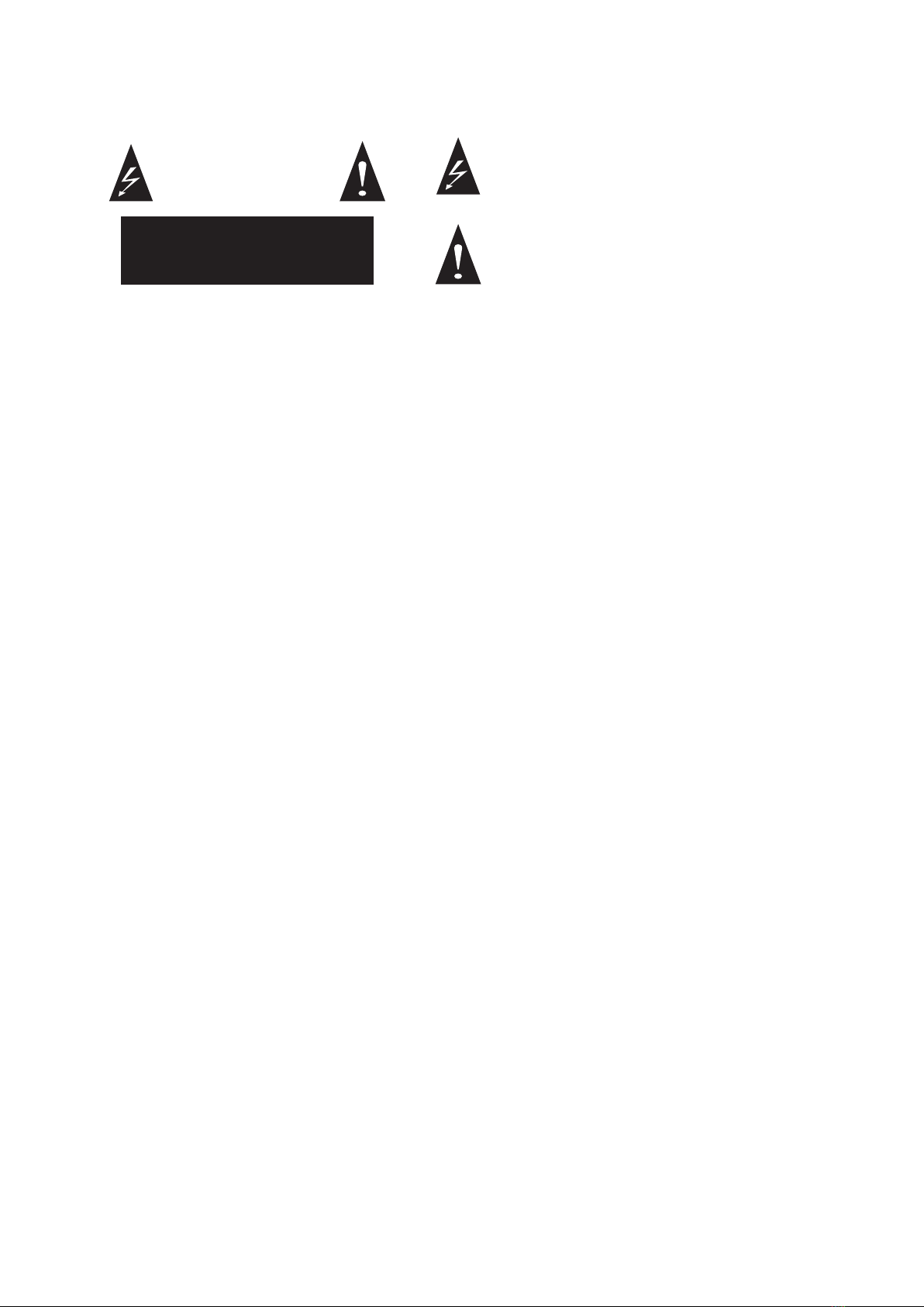
CAUTION
RISK OF ELECTRIC SHOCK
DO NOT OPEN
CAUTION: TO REDUCE THE RISK OF ELECTRIC
SHOCK CO NOT REMOVE COVER(OR BACK)
NO USER-SERVICEABLE PARTS INSIDE
REFER SERVICING TO QUALIFIED PERSONNEL
The exclamation point within an equilateral triangle is
intended toalert the user to the presence of important
operation an maintenance (servicing) instruction in the
literature accompanying the appliance.
IMPORTANT SAFETY INSTRUCTION
SAVE THESE INSTRUCTIONS
The lightning flash with arrowhead symbol within an
equilateral triangle is intended to alert the user to the presence
of uninsulated dangerous voltage within the product's
enclosure, that may be of sufficient magnitude to constitute
a risk of electric shock to persons.

The main differences between J2 and J2+ systems.........................................1
...................................................2How to set up for a J2 Active mobile system
H102 detailed specification...........................................................................3
DSP18A detailed specification......................................................................4
Parts list......................................................................................................5
DSP18A Amplifier Funtions...........................................................................6
Hi-Fi Class D Amplifier Module and high quality switching power Module..........6
.................................7Drawing for internal structure view and cable connection
How to control DSP18A by your computer..................................................8-11
Loudspeaker connection 1 (MONO SUPPORT MODE )..................................12
Loudspeaker connection 2 (MONO STACK MODE ).......................................12
.............................13Loudspeaker connection 3 (LINE ARRAY STACK MODE )
Loudspeaker connection 4 (LINE ARRAY MODE A) .......................................13
Loudspeaker connection 6 (LINE ARRAY MODE B ).......................................14
Accessory Manual.......................................................................................15
MONO (SUPPORT) MODE installation metho................................................16
MONO(STACK) mode installation method.....................................................17
Line array installation method......................................................................18
DJ table installation method.........................................................................18
CATALOGUE

Introduction of J2
J2
J2+
J2 SYSTEM is showed by engineers 2 years devotion to develop,combined
with domestic and international market requirement, come out of this Orinination and
Unique active multifunctional touring sound system!
Active Multifunctional Touring SOUND SYSTEM
Therefore, this user manual is suitable for both J2 and J2+ systems.
The main differences between J2 and J2+ systems.
① H102+ is powered by Neodymium driver & woofer in J2+ system, but it is the normal
ferrite driver & woofer in H102 in J2 system.
③There is one Horizontal bar symbol in the Stoma of DSP18A, but there are two Horizontal
bar symbols in the Stoma of DSP18A+.
②DSP18A+ is powered by Neodymium woofer in J2+ system, but it is the normal ferrite
driver & woofer in DSP18A in J2 system.
The main differences between T2 and T2+ systems.
H102 Ferrite driver
(Customer-made)
H102 Ferrite driver
(Customer-made)
DSP18A Ferrite driver
(Customer-made)
H102+ Neodymium
driver .
(Customer-made)
H102+ Neodymium
driver .
(Customer-made)
DSP18A+ Neodymium
driver .
(Customer-made)
There is one Horizontal
bar symbol in the Stoma
of DSP18A.
There are two Horizontal
bar symbols in the Stoma
of DSP18A+.
J2

How to set up for a J2 Active mobile system
2
MONO(STACK)MODE A
MONO(STACK)MODE B
MONO(SUPPORT)MODE
LINE ARRAY MODE
Active Multifunctional Touring SOUND SYSTEM
J2

H102 TECHNICAL SPECIFICATION
H102 FEATURES
H102 TECH DRAWING
314 mm
540 mm 314 mm
314 mm
540 mm
314 mm
3
Active Multifunctional Touring SOUND SYSTEM
Type......................................... Horn Loaded Mid-Hi
Component..................................... 10"+2"×2+ Horn
Nominal Impedance............................................. 8Ω
RMS Power Handling........................................350W
Peak Power Handling....................................... 700W
Frequency Response.............................55Hz-19KHz
Sensitivity(1W/1M)............ H102/102dB;H102+/103dB
Max. SPL........................................................ 130dB
Dispersions....................................120°H×10° V
Horn throat size.......................................... 1"(25mm)
Voice coil size............................................ 2"(44mm)
Crossover......................................................1.5KHz
Dimension HWD(mm).......................... 314×540×314
Shipping HWD(mm)..............380×610×390(0.09CBM)
NW/GW(Kg).................H102(21/22.7);H102+(17/18.7)
Ergonomic Handle
Efficient Directional Horn
(120°Hx10°V)
Easy Aluminum Hanging Slot
Elevation-adjustable Hanging
Facilities
(0、3、5、8 )
Strong and Durable Stand Holder
J2

595 mm 830 mm
684 mm
595 mm
830 mm
684 mm
860 mm
850 mm
860 mm
850 mm
4
Active Multifunctional Touring SOUND SYSTEM
DSP18A TECHNICAL SPECIFICATION
DSP18A FEATURES
DSP18A TECH DRAWING
Type.................................................... Active Sub Woofer
Component.............................................................18"×1
Nominal Impedance.......................................................8Ω
RMS Power Handling.................................................600W
Peak Power Handling...............................................1200W
Frequency Response.......................................40Hz-250Hz
Sensitivity(1W/1M).............DSP18A/104dB;DSP18A+/105dB
Max. SPL..................................................................131dB
Output............... 1×600W+2×450W Digital Power Amp
Power supply..........High quality Switching power supply
Processor...................... 32BIT, 2 In 4 Out DSP Module
Dispersions...................................................................N/A
Dimension HWD(mm)....................................850×594×684
Shipping HWD(mm).................... 970×690×930(0.622CBM)
NW(Kg)......................................DSP18A/73.5;DSP18A+/70
GW(Kg).....................................DSP18A/132;DSP18A+/120
(Including 2pcs AP102 + 1pc AP118)
1
Lockable Wheel, design for the mobile
show.
2
Unique Storing and Transport Mode,
can store 2 pcs H102 inside.
3
4
Long hard Alloy Stand Holder.
5
Aluminum Alloy Anticollision corner,
p r o t e c t t h e lo u d s p e a k e r w h i l e
transporting.
6
Active power amplifier cover,protect
amplifier with nice look.
Multifunctional cover, expansionof DJ table,
convenient disassembly and assembly, less
occupied space, convenient carrying and
high utility.
J2

Parts list
5
Active Multifunctional Touring SOUND SYSTEM
Easy install and uninstallportable DJ
table and cover.
Standard Accessories
DSP18 loudspeaker protect cover 1 Ton hoist
power plug cable All weather rain cover
4-Core Speaker Cable(Long)
Power Cord for DSP18A 4-Core Speaker Cable(Short)
Adjustable Tripod (use in mono
support mode )
Optional Accessories
Handle lifting rod
RS485-USB cable
T model trapeze (for option)
J2

6
Active Multifunctional Touring SOUND SYSTEM
DSP18A Amplifier Funtions
Digital Module
(450W)
Switching power + Digital module(600W)
Hi-Fi Class D Amplifier Module and high quality switching power Module
Digital Module
(450W)
1SUB Input mode Convertor
2FULL Input
3
4
5
6
7
9
10
11
12
13
8
14
15
16
17
18
19
20
21
22
CR OS S 4- CO RE CA BE L
T2/T2+
交叉四芯音箱线
MOD E
Wh en t he b ut t on i s on , a nd t he i np ut m od e wi ll b e th e
fu ll ra ng e i np ut w it h bo th c ha nn el .
4- CO RE C AB EL
T2 P RO
四芯音箱线
4- CO RE C AB EL
VOL. VOL.
MODE
1 2
3 4 5
1. 室 内 模式 /i n do or
2. 室 外 模式 /o u td oo r
3. 室 内 叠加 模式 / st al kin g fo r ind oo r
4. 室 外 叠加 模式 / st al kin g fo r out do or
5. 复 位 /d ef i re d mo de
MODE FULL INP UT
按键 弹 起时 ,输 入 模式 为单 线全频 输入
MODE FULL+SUB IN PUT
按键 按 下时 ,输 入 模式 为全 频与低 音可 单独控 制
Wh en p us hi n g bu tt on , t he i np ut m od e wi ll b e th e si ng le
mo de b y co nt r ol f ul lr an ge o r Su b ba ss c ha nn el s ol o.
FULL
INPU T
FULL +SUB
INPU T
FUL L OUTPU T
±1 LF ±2 HF
FUL L
INP UT
LIN K
SUB
INP UT
LIN K
2×4
DS P
1
2
3
4
SU B
MI D
HI
CU S
AM P
3c h.
MI D ±1
HI ±2
18 "
SU B
INPUT
CA T 5 PC
US B U SB
48 5
FUL L OUTPU T
±1 LF ±2 HF
EX P .
MID/HI SUB
Air inlet
Air outlet
AC Power Indicator
Signal Indicator
Protection Indicator
Sub Volume Control
Full Volume Control
USB/485 Terminal
AC Power output Socket
AC Power input Socket
Fuse
Power on/off
Mo d e Indicator
FULL Link
SUB Input
SUB Link
FULL Output(±1MID;±2HI)
IN
OUT
485
Switch for input sigal connection with
earth zero connection way
LED for Peak Value
Mode selction knob
J2

7
Active Multifunctional Touring SOUND SYSTEM
2
3
1
VOL. VOL.
FULL
INPUT
FULL+SUB
INPUT
FULL
INPUT
LINK
SUB
INPUT
LINK
SUB TOP 1
TOP 2
PC
MID/HI SUB
AMP
3ch.
2×4 DSP
CUS Control Unit EXP.
1
2
3
1
2
MODE
FULL OUTPUT
±1 LF ±2 HF
SUB
INPUT
4-CORE CABEL
4芯音箱线
4-CORE CABEL
交叉4芯音箱线
FULL SPRAKER
18"
N/L 4
8Ω
8Ω
+2
-2
+1
-1
+2
-2
+1
-1
TOP 1
TOP 2
Drawing for internal structure view and cable connection
Connection for sound singal input
Switch for Bass input connection
and selection
volume setup knob for High
Frequancy and Sub bass
Connetcion and switch for
selection which drived by
the third amplifier for Sub bass
the guide for sound
cable with 4-pole
Selection for other
function in the future
18 inch Speaker
woofer unit
USB
Connection plug
USB Connection Cable
The Guide for programing
1.Indoor solo mode
2.outdoor solo mode
3.2+4 indoor mono stack mode
4.2+4 outdoor mono stack mode
5.reset mode
When error by setup with computer ,
use this mode to reset the default mode
All process for reset will erase the currently mode by user ,
so before operating this , please copy back all the specification
into the computer.
Mode selction knob * Switching on it when amplifier module was broken ,and
Sub woofer will be worked by the third out-connection
amplifier.
* fast continuely working and repairing by choosing special
designing amplifier which produced by our factory .
DSP18A can be connected easily with computer
or directly connect to 485 net cable .
a . Installing the USB or 485 driving programe
b . Installing the control software for DSP18A
All signal input connection must be used the cable with
shield earth protection ,So it can protection the device
for blance inputingotherwise , echo will be caused by
Ground Loop.
pin 1-GROUND, Pin 2-HOT, Pin3-COLD
USB/485 Network cable
J2

8
Active Multifunctional Touring SOUND SYSTEM
1.Open the software and select the language , the default mode is ENGLISH .
Language seletive operation: Utilty->Language->ENGLISH。
4.
How to control DSP18A by your computer
2. Select in the Device option, this is suit for J2 system.
Use USB connection cable to build up the connection bewteen computer and J2 system
and make sure the full instalation of J2 control software and driving programein the
computer. Switch on the J2 power ,and check the "device"of J2 software and check the
"com" and make sure the right cable connection between computer and device and check
the com plug model and remember it , open the J2 software and select the USB option in the
"communication management" and click "connect" and wait for some mins the connection
between computer and J2 will be finished.
3.
Enter "flow chart" here shows all the signal flow at current if you want to make setting ,Just
enter the interface shows ;And you can shift the tags and finish it .
J2

9
Active Multifunctional Touring SOUND SYSTEM
How to control DSP18A by your computer
5. Controlled parameter
① Channel selection : Default mode input 1 is Sub bass , input 2 ,Low-mid range for
Full frequancy input 3 : Low range for High frequancy , Input 4: not setup.
② Make sure the X-over parameter and the working signal range of this input channel ,
Doubleclick the parameter for High frequancy channel or Bass frequancy channel and
edit it by using Ordinate Menu , the frequancy of cross-over point is 1/36 times ,Max
frequancy can bereach 48Db ( if the frequancy is more bigger and the transition zone
of cross-over point will be more steep .
J2

10
Active Multifunctional Touring SOUND SYSTEM
How to control DSP18A by your computer
③ Optimize loudspeaker frequency response curve,After finish setting X-over and parameter
(make sure the working signal range of this ourput channel) Use output channel'PEQ ,User can
double click and enter into the parameter setting Menu ,and you can adjust by EQ'S active cursor
on the frequency content , Active the cursor , need to click the correspondingcolorful button,And
click right key on the frequenc content ,It will show as ordinate menu.
J2

11
Active Multifunctional Touring SOUND SYSTEM
④ setup the distance of all speaker cabinets , and erase the time error of the system by
adjusting the parameter of relay for each channel and make sure the Synchronous output for
each channels of all cabinets.
⑤ Setup up the max output value of each channel and make sure all singal output value which
can not over the permited value of each channel.
⑦ All saved and selected parameter will be save in the computer {check the programe management )
and it can be selected in any time when using.
⑥ select and save the parameter of each output channel,Click the interface of any channels and
select the "setting " and select "save" in any interface , and all parameter of channels can be saved
and selected.
How to control DSP18A by your computer
Coarse tuning and Fine tuning parameters
J2

12
Active Multifunctional Touring SOUND SYSTEM
Loudspeaker connection 2 (MONO STACK MODE )
FULL IN
AC IN AC IN
MIXER
CD
L R
OUTPUT
INPUT
INPUT
LINK
OUTPUT
INPUT
INPUT
LINK
FULL IN
FULL OUT
FULL OUT
OUTPUT
INPUT
LINK
INPUT
OUTPUT
INPUT
LINK
INPUT
OUTPUT
INPUT
INPUT
LINK
OUTPUT
INPUT
INPUT
LINK
SUB IN (Optional)
FULL OUT
MIXER
CD
RL
AC IN
AC IN
LINK
AC IN
AC IN
FULL IN
FULL OUT
FULL IN
LINK
±1 top1
±2 top2
±1 top1
±2 top2 ±1 top1
±2 top2
±1 top1
±2 top2
±1 top1
±2 top2 ±1 top1
±2 top2
±1 top1
±2 top2 ±1 top1
±2 top2
±1 top1
±2 top2 ±1 top1
±2 top2
±1 top1
±2 top2 ±1 top1
±2 top2
Loudspeaker connection 1 (MONO SUPPORT MODE )
SUB IN (Optional)
SUB IN (Optional) SUB IN (Optional)
Use 4-pole speaker cable
J2

13
Active Multifunctional Touring SOUND SYSTEM
Loudspeaker connection 4 (LINE ARRAY MODE A )
FULL OUT
CD
RL
LINK
FULL OUT
LINK
FULL OUT
FULL OUT
MIXER
OUTPUT
OUTPUT
INPUT
LINK
OUTPUT
INPUT
INPUT
LINK
INPUT
INPUT ±1 top1/±2 top2
INPUT
INPUT
LINK
INPUT
LINK
LINK
OUTPUT
OUTPUT
INPUT
LINK
INPUT
INPUT
LINK
LINK
OUTPUT
INPUT
INPUT
LINK
INPUT
INPUT
LINK
OUTPUT OUTPUT
LINK LINK
AC IN
AC IN
AC IN
AC IN
FULL IN
MIXER
CD
RL
FULL IN
OUTPUT
INPUT
LINK
OUTPUT
INPUT
LINK
INPUT
OUTPUT
INPUT
LINK
INPUT
OUTPUT
INPUT
LINK
±1 top1
±2 top2 INPUT
±1 top1
±2 top2
INPUT
±1 top1
±2 top2
±1 top1
±2 top2
±1 top1
±2 top2
±1 top1
±2 top2
±1 top1
±2 top2 ±1 top1
±2 top2
INPUT ±1 top1/±2 top2
±1 top1
±2 top2
±1 top1
±2 top2
FULL IN
FULL IN
FULL IN
FULL IN
Loudspeaker connection 3 (LINE ARRAY STACK MODE )
4-pole
jumper
cable
Use 4-pole speaker cable
SUB IN (Optional)
SUB IN (Optional)SUB IN (Optional)
SUB IN (Optional)
Use 4-pole speaker cable
SUB IN (Optional)SUB IN (Optional)
J2

MIXER
CD
RL
TP4130
AMPLIFIER
Use 4-pole speaker cable
OUTPUT ±1 top1/±2 top2I
LINK
INPUT
INPUT±1 top1/±2 top2
LINK
INPUT
OUTPUT ±1 top1/±2 top2I
±1 top1
±2 top2
INPUT±1 top1/±2 top2
±1 top1
±2 top2
Loudspeaker connection 4 (LINE ARRAY MODE B )
14
Active Multifunctional Touring SOUND SYSTEM
TP4130
AMPLIFIER
J2

15
Active Multifunctional Touring SOUND SYSTEM
Accessory Manual
H102 loudspeaker placed method:
1.DSP18A can be placed 2 pcs H102
inside.
3.Please keep H102 in the opposite side
in the DSP18A, if not,H102 will collide
each other while transporting
Protect Cover installation method:
1.Match loudspeaker and protect
cover with alloy lock catch and loosen
the lock catch anticlockwise.
2.Double check the protect cover and
loudspeaker if close entirely or not, if
not, please adjust the protect cover
and tie it clockwise.
NOTE:
Please keep horizontal moving while
pushing in order to avoid accident。
2.Please place H102 Vertical always
and you can put H102 into DSP18A
sub hole easily (See left picuture ①).
J2

MONO (SUPPORT) MODE installation metho
zc-2 zc-3
zc-1
16
Active Multifunctional Touring SOUND SYSTEM
③ Setting up for the second H102,pls take out
the 2pcs connected parts from bothsides of the
first H102,and lift the second H102 to stack up
on it.pls make sure to let the connected parts to
insert into the correct space before you lock it
by the pins.finally,pls put the rear connected part
from the first H102 into the rear of second H102
and select the working angle as you need before
you lock it by the pin. Pls see attached picture zc-3.
①Pls put the DSP18A on the ground, take out
the speaker pole and insert into the hole of
DSP18A, then adjust the working hight as you
need. Pls see attached picture ZC-1.
② Setting up for the first H102, pls Lift the first
H102 and let it insert into the speaker pole, pls
see attached piture zc-2.
J2

17
Active Multifunctional Touring SOUND SYSTEM
MONO(STACK) mode installation method
Ref:dd-2 Ref:dd-3 安装完成
Ref:dd-1
Ground stacked the 2 subs, and install the H frame by locking the two
screws. Ref.: dd-1
Load 1 top on the H frame in right position and insert the two sides lock
pins; adjust the back rigging angle and insert the one lock pin. Ref.: dd-2
Get the first top’s front rigging point out and load the second top same
as Process dd-2. Finish all the installation process like this. Ref.: dd-3
①
②
③
J2
Table of contents