2
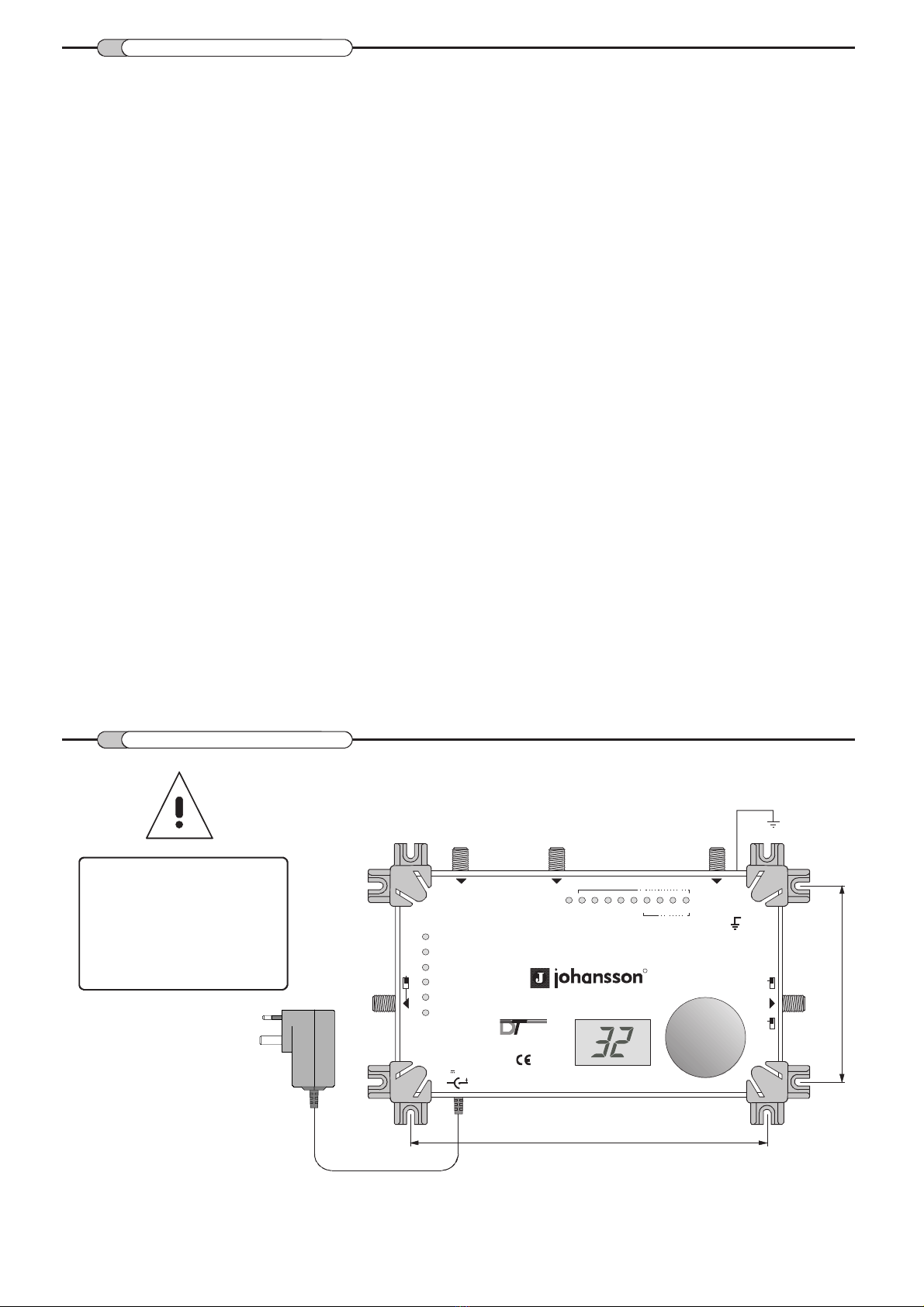
MOUNTING
SAFETY INSTRUCTIONS
98 mm.
177 mm.
Grounding
Read carefully these instructions before connecting the unit.
The operating voltage is indicated on the adapter.
To prevent fire, short circuit, shock hazard:
Do not expose the unit to rain or moisture.
Install the unit in a dry location without infiltration or condensation of water.
Do not expose it to dripping or splashing.
Do not place objects filled with liquids, such as vases, on the apparatus.
If any liquid should accidentally fall into the cabinet, disconnect the power plug.
Refer to qualified technician before it's further operation.
To avoid any risk of overheating:
Install the unit in a well aery location and keep a minimum distance of 15 cm around the apparatus for
sufficient ventilation.
Do not place any items such as newspapers, table-cloths, curtains ... on the unit that might cover the ventilation holes.
The unit must not be exposed to any source of heat (sun, heater,...).
Do not place any naked flame sources, such as lighted candles, on the apparatus.
Do not install the product in a dusty place.
Pull out power plug to make the different connections of cables.
To avoid electrical shock, do not open the housing of adapter.
Cleaning :
Only use a dry soft cloth to clean the cabinet. Do not use solvent.
Servicing :
For repairing and servicing refer to qualified personnel.
WARNING !
Use only supplied power
adapter.
A different voltage and/or
wrong polarity destroys
the equalizer
beyond repair!
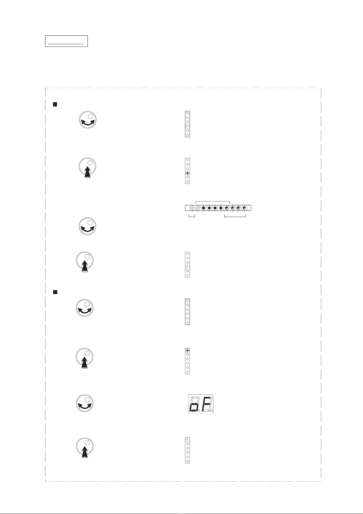
Split UHF
MULTI CHANNEL PROGRAMMABLE FILTER-EQUALIZER
OUT
UHF
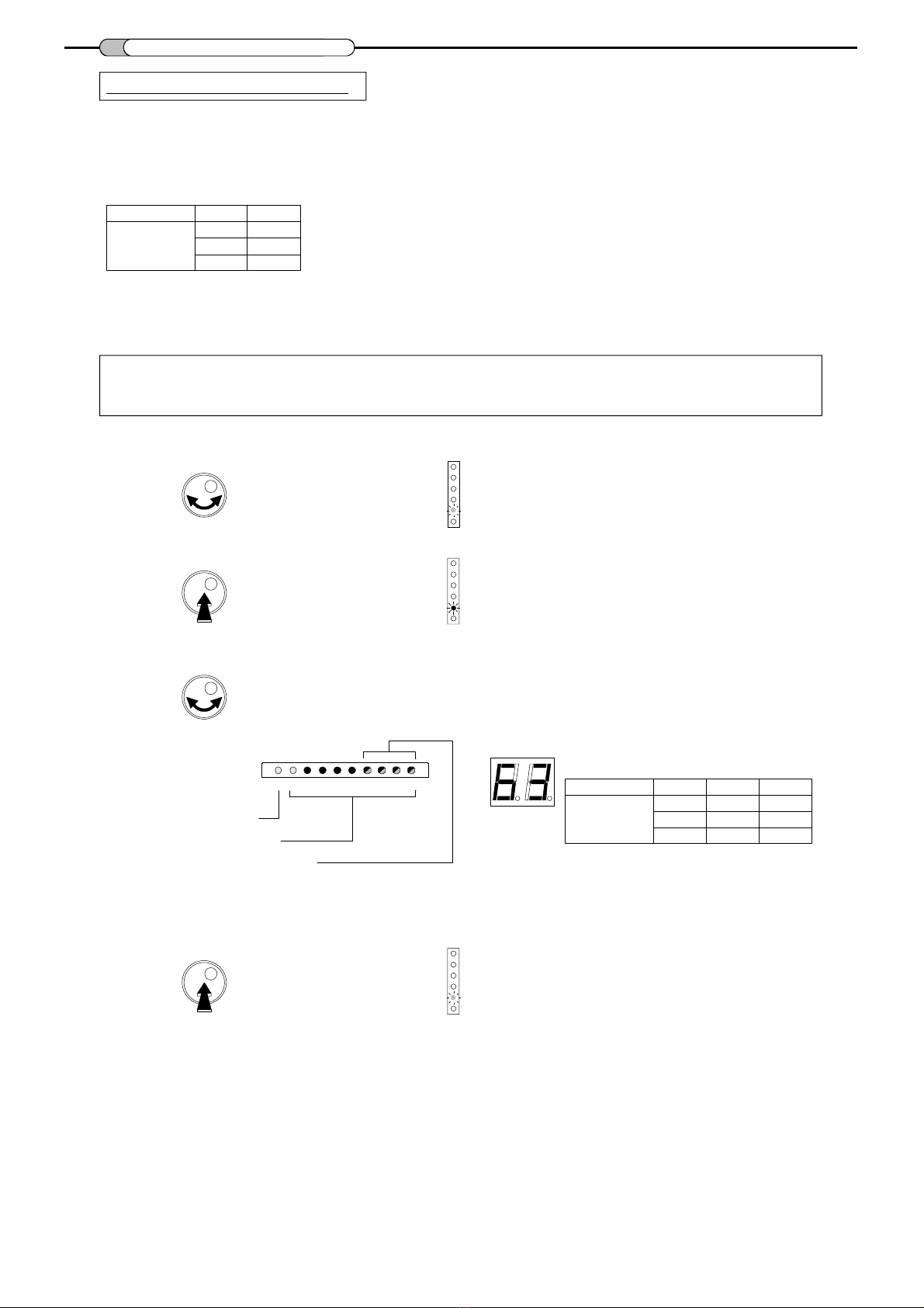
Filter & Input Selection
Start
Stop
VHF
Level
2FHU1FHU
R
Ref. : 6505
Digital
Terrestrial
DC
UHF1
DC
UHF2
GND
+5V
/500 mA
VHF
2 3
4 5
6
7
8
9
UHF1
UHF2
1
VHF
OUT
DC
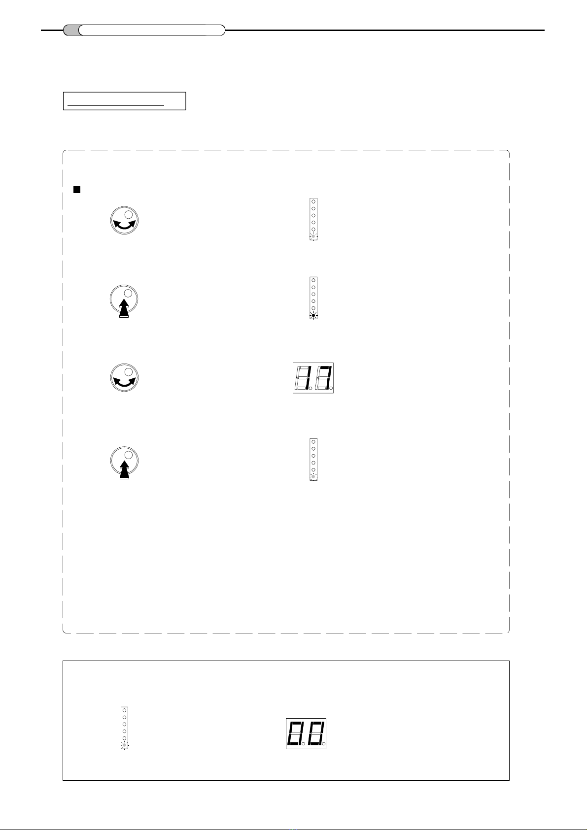
Preset : 01~40
00 :
programmable