-8-
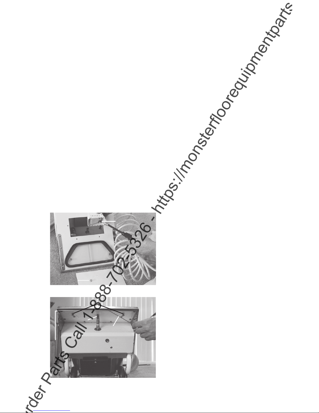
Figure 26: Cleaning Vacuum Shoe
4. Clean Air Filter (figure 23). At least
once or twice a month the air filter
should be removed and cleaned. Be-
gin by removing the wingnut, nylon
washer and the middle brace, then
pull out the air filter (figure 23). Thor-
oughly clean the air filter. When re-
placing the air filter, make sure it is
positioned properly around the black
plastic baffle. Then as you are retight-
ening the wingnut, push up on the
middle brace to make sure it seats flat
against the inside of the recovery tank.
Do not operate the machine without
the air filter. Doing so will dramati-
cally reduce the life and performance
of your vacuum motor.
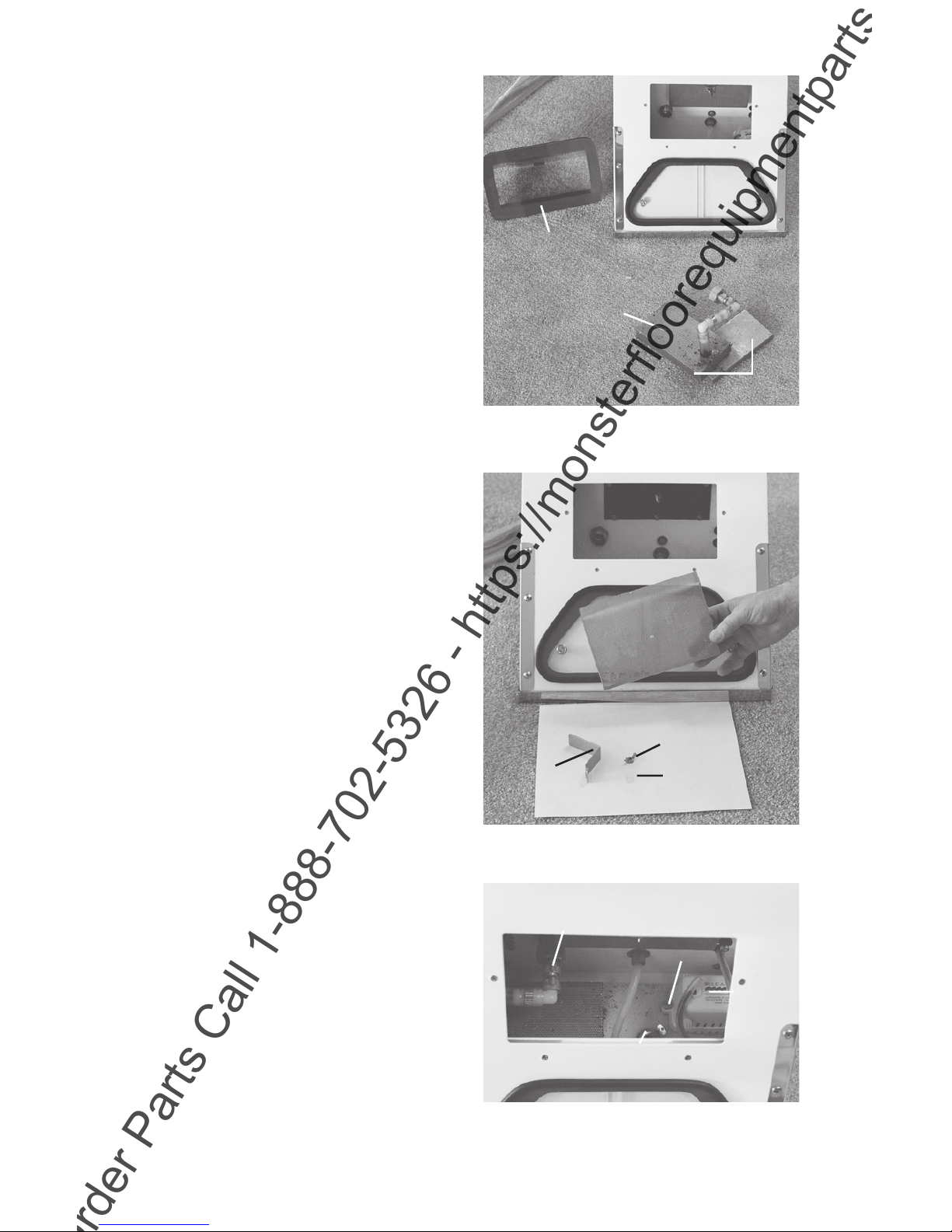
5. Clean Float Switch (figure 25). Un-
screw brass thumbnut (figure 24) and
lift up the float switch. Use your
spray wand to spray out any debris
that may have collected inside the
plastic housing.
6. Remove drain plug and spray out bot-
tom of recovery tank with prespray
wand.
7. Remove and clean water channel by
removing thumbnuts from underside
of machine (figures 25 and 26).
8. Clean vacuum shoe with shoe hook
(figure 26).
9. Replace drain plug, float switch, wa-
ter channel and water filter. (Make
sure the water filter sits flat on the
bottom of the recovery tank before
tightening its garden hose swivel nut).
10. Watch for any hair and lint build up
between axle and wheel bearings.
11. Clean machine exterior with a damp
cloth and window cleaner.
IMPORTANT: A powder coating cov-
ers the marine-grade aluminum shell of
the machine. Over time, this coating will
chip or flake off, especially in areas such
as the inside of the recovery tank. A
spray paint such as Rustoleum may be
used to touch up the finish.
12. Plug machine back in and start
vacuum motor to remove any mois-
ture that may have entered it during
the cleaning process. Leave vacuum
motor on for about a minute; then
unhook machine.
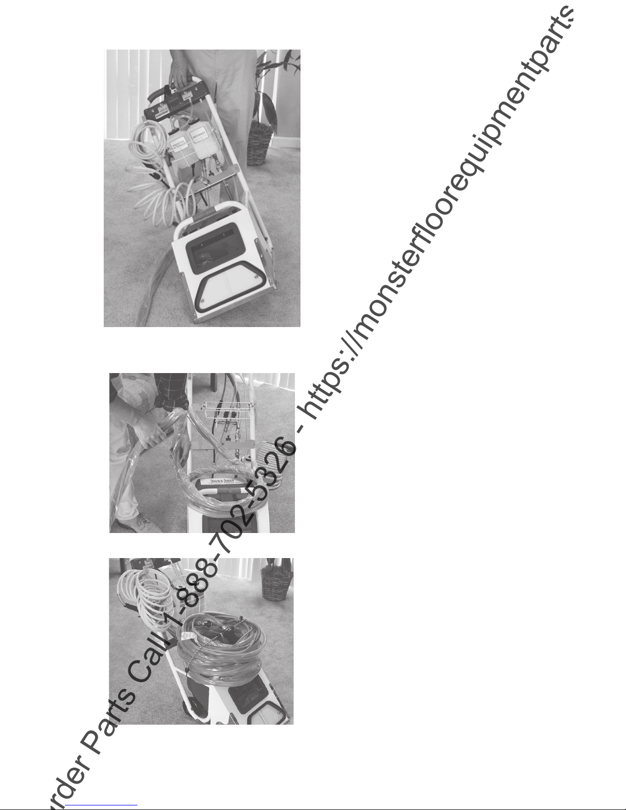
VII. Hoses
A. To remove regular 50 foot hose
assembly from machine:
1. Unscrew machine’s drain valve assem-
bly from the drain line hose whip
swivel fitting (figure 27).
2. Unplug electrical connection.
3. Unscrew the pressure line’s garden
hose swivel nut from the prespray
assembly.
IMPORTANT: a garden hose screen
washer is located within this swivel nut.
Water Channel Thumb Nuts
Side Vacuum Slot
Lip Hook
Spray Jet
Figure 25: Cleaning the Float Switch
Thumb Nut
Float Switch
Water Channel
ToOrderPartsCall1-888-702-5326-https://monsterfloorequipmentparts.com