Johnson Controls Ducted Systems 6284251-UIM-B-0223
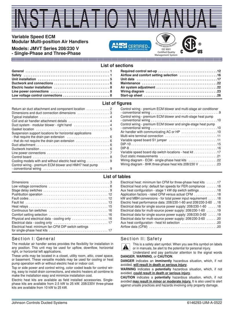
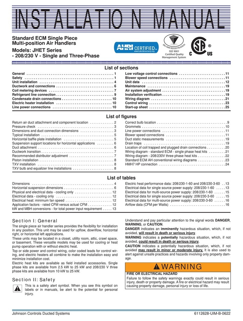
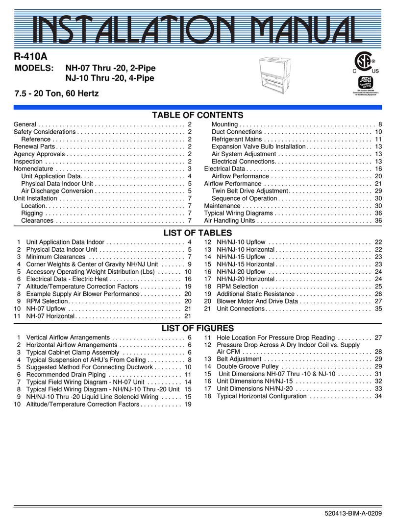
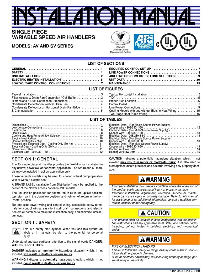
Premium Variable Speed
ECM Single Piece
Multi-position Air Handlers
Models: JHVV Series
INSTALLATION MANUAL
List of sections
General . . . . . . . . . . . . . . . . . . . . . . . . . . . . . . . . . . . . . . . . . . . . . . . 1
Safety . . . . . . . . . . . . . . . . . . . . . . . . . . . . . . . . . . . . . . . . . . . . . . . . 1
Unit installation . . . . . . . . . . . . . . . . . . . . . . . . . . . . . . . . . . . . . . . . 4
Ductwork and connections . . . . . . . . . . . . . . . . . . . . . . . . . . . . . . . 6
Coil metering devices . . . . . . . . . . . . . . . . . . . . . . . . . . . . . . . . . . . 7
Refrigerant line connection . . . . . . . . . . . . . . . . . . . . . . . . . . . . . . . 7
Condensate drain connections . . . . . . . . . . . . . . . . . . . . . . . . . . . . 8
Electric heater installation . . . . . . . . . . . . . . . . . . . . . . . . . . . . . . . 8
Line power connections . . . . . . . . . . . . . . . . . . . . . . . . . . . . . . . . . 8
Low voltage control connections . . . . . . . . . . . . . . . . . . . . . . . . . . 9
Airflow and comfort setting selection . . . . . . . . . . . . . . . . . . . . . 16
Unit data . . . . . . . . . . . . . . . . . . . . . . . . . . . . . . . . . . . . . . . . . . . . . 17
Maintenance . . . . . . . . . . . . . . . . . . . . . . . . . . . . . . . . . . . . . . . . . . 21
Air system adjustment . . . . . . . . . . . . . . . . . . . . . . . . . . . . . . . . . . 21
Installation verification . . . . . . . . . . . . . . . . . . . . . . . . . . . . . . . . . 22
Wiring diagrams . . . . . . . . . . . . . . . . . . . . . . . . . . . . . . . . . . . . . . . 23
Start-up sheet . . . . . . . . . . . . . . . . . . . . . . . . . . . . . . . . . . . . . . . . . 25
List of figures
Return air duct attachment and component location . . . . . . . . . . . . . 2
Pressure check . . . . . . . . . . . . . . . . . . . . . . . . . . . . . . . . . . . . . . . . . 3
Dimensions and duct connection dimensions . . . . . . . . . . . . . . . . . . 3
Typical installation . . . . . . . . . . . . . . . . . . . . . . . . . . . . . . . . . . . . . . . 5
Horizontal baffle plate installation . . . . . . . . . . . . . . . . . . . . . . . . . . . 5
Suspension support locations for horizontal applications . . . . . . . . . 6
Duct attachment . . . . . . . . . . . . . . . . . . . . . . . . . . . . . . . . . . . . . . . . . 6
Ductwork transition . . . . . . . . . . . . . . . . . . . . . . . . . . . . . . . . . . . . . . . 7
Grommets . . . . . . . . . . . . . . . . . . . . . . . . . . . . . . . . . . . . . . . . . . . . . 8
Line power connections . . . . . . . . . . . . . . . . . . . . . . . . . . . . . . . . . . . 9
Control board . . . . . . . . . . . . . . . . . . . . . . . . . . . . . . . . . . . . . . . . . . . 9
EEV connectors . . . . . . . . . . . . . . . . . . . . . . . . . . . . . . . . . . . . . . . . 10
Air handler with communicating AC or HP . . . . . . . . . . . . . . . . . . . . 11
Multi-wire terminal connection . . . . . . . . . . . . . . . . . . . . . . . . . . . . . 11
DIP-10 . . . . . . . . . . . . . . . . . . . . . . . . . . . . . . . . . . . . . . . . . . . . . . . 16
DIP-8 . . . . . . . . . . . . . . . . . . . . . . . . . . . . . . . . . . . . . . . . . . . . . . . . 16
Variable speed board dip switch locations - heat kit . . . . . . . . . . . . . 17
Duct static measurements . . . . . . . . . . . . . . . . . . . . . . . . . . . . . . . . 21
Drain traps . . . . . . . . . . . . . . . . . . . . . . . . . . . . . . . . . . . . . . . . . . . . 22
Location of coil trapped and plugged drain connections . . . . . . . . . 22
Wiring diagram - EEV . . . . . . . . . . . . . . . . . . . . . . . . . . . . . . . . . . . . 23
Wiring diagram . . . . . . . . . . . . . . . . . . . . . . . . . . . . . . . . . . . . . . . . . 24
List of tables
Dimensions . . . . . . . . . . . . . . . . . . . . . . . . . . . . . . . . . . . . . . . . . . . . 4
Horizontal suspension dimensions . . . . . . . . . . . . . . . . . . . . . . . . . . . 6
EEV Connectors . . . . . . . . . . . . . . . . . . . . . . . . . . . . . . . . . . . . . . . . 10
Low voltage connections . . . . . . . . . . . . . . . . . . . . . . . . . . . . . . . . . 11
Pushbutton operation . . . . . . . . . . . . . . . . . . . . . . . . . . . . . . . . . . . . 12
Fault codes . . . . . . . . . . . . . . . . . . . . . . . . . . . . . . . . . . . . . . . . . . . . 13
Fault list . . . . . . . . . . . . . . . . . . . . . . . . . . . . . . . . . . . . . . . . . . . . . . 13
Heat relays . . . . . . . . . . . . . . . . . . . . . . . . . . . . . . . . . . . . . . . . . . . . 15
Continuous fan switches . . . . . . . . . . . . . . . . . . . . . . . . . . . . . . . . . 16
Comfort setting selection . . . . . . . . . . . . . . . . . . . . . . . . . . . . . . . . . 16
Physical and electrical data - cooling only . . . . . . . . . . . . . . . . . . . . 17
Electrical data - cooling only . . . . . . . . . . . . . . . . . . . . . . . . . . . . . . 17
Electrical heat: minimum fan CFM for single-phase heat kits . . . . . . 17
Electrical heat: minimum fan CFM for three-phase heat kits . . . . . . 18
Aux heat configuration - stage 1 kW dip switch settings . . . . . . . . . 18
Application factors - rated CFM versus actual CFM . . . . . . . . . . . . . 18
kW and MBH conversions - for total power input requirement . . . . . 18
Electric heat performance data: 208/230-1-60 and 208/230-3-60 . . 18
Electrical data for single source power supply: 208/230-1-60 . . . . . 19
Electrical data for multi-source power supply: 208/230-1-60 . . . . . . 19
Electrical data for single source power supply: 208/230-3-60 . . . . . 20
Electrical data for multi-source power supply: 208/230-3-60 . . . . . . 20
Temporary repair mode cooling airflow data (CFM) . . . . . . . . . . . . . 21
Section I: General
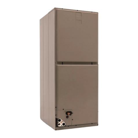
The single piece air handler series provides the flexibility for installation
in any position. This unit may be used for upflow, downflow, horizontal
right, or horizontal left applications.
These units may be located in a closet, utility room, attic, crawl space,
or basement. These versatile models may be used for cooling or heat
pump operation with or without electric heat.
Top or side power and control wiring, color coded leads for control wir-
ing, and electric heaters all combine to make the installation easy and
minimize installation cost.
Electric heat kits are available as field installed accessories. Single-
phase kits are available from 2.5 kW to 25 kW and 208/230 V three-
phase kits are available from 10 kW to 25 kW.
Section II: Safety
This is a safety alert symbol. When you see this symbol on labels
or in manuals, be alert to the potential for personal injury.
Understand and pay particular attention to the signal words DANGER,
WARNING, or CAUTION.
DANGER indicates an imminently hazardous situation, which, if not
avoided, will result in death or serious injury .
WARNING indicates a potentially hazardous situation, which, if not
avoided, could result in death or serious injury.
CAUTION indicates a potentially hazardous situation, which, if not
avoided may result in minor or moderate injury. It is also used to alert
against unsafe practices and hazards involving only property damage.
WARNING
FIRE OR ELECTRICAL HAZARD
Failure to follow the safety warnings exactly could result in serious
injury, death or property damage. A fire or electrical hazard may result
causing property damage, personal injury or loss of life.
!
