PMGB0406B rev.1 4
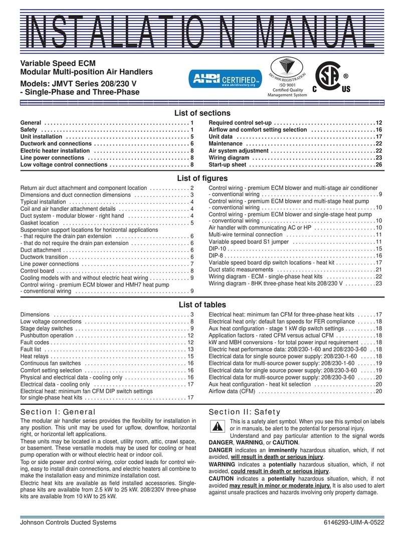
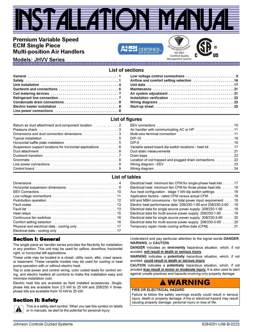
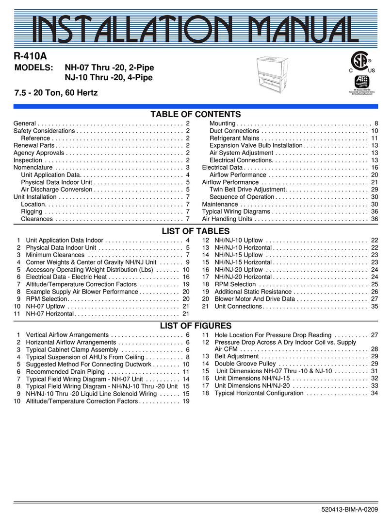
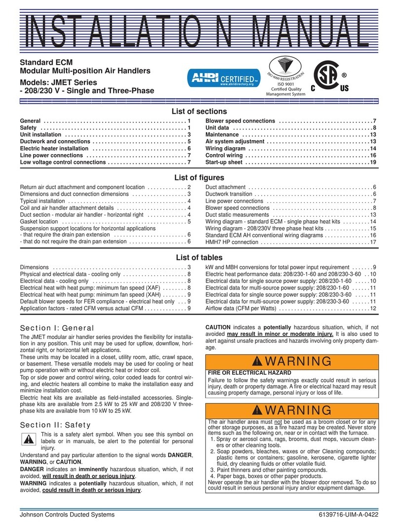
List of Figures
Figure 1. Return Air Duct Attachment and Component Location ........................................................................ 7
Figure 2. Pressure Check................................................................................................................................... .8
Figure 3. Dimensions and Duct Connection Dimensions.................................................................................... 8
Figure 4. Typical Installation.............................................................................................................................. 11
Figure 5. Coil Blow Off Wing Installation........................................................................................................... 12
Figure 6. Horizontal Suspension ....................................................................................................................... 14
Figure 7. Duct Attachment................................................................................................................................ .14
Figure 8. Duct Work Transition.......................................................................................................................... 15
Figure 9. Line Power Connections .................................................................................................................... 19
Figure 10. Factory Wired Blower Connections.................................................................................................... 20
Figure 11. Duct Static Measurements................................................................................................................. 29
Figure 12. Drain Traps......................................................................................................................................... 30
Figure 13. Location of Coil Trapped and Plugged Drain Connections ................................................................ 30
Figure 14. DX-Kit in the VRF system .................................................................................................................. 38
Figure 15. Installation Space............................................................................................................................... 42
Figure 16. Installation Dimensions ...................................................................................................................... 43
Figure 17. Mounting the Control Box................................................................................................................... 44
Figure 18. Mounting Valve Box ........................................................................................................................... 45
Figure 19. Details of Mounting Hole .................................................................................................................... 45
Figure 20. Piping Connections ............................................................................................................................ 47
Figure 21. Flare Dimensions ............................................................................................................................... 47
Figure 22. Applying Refrigerant Oil ..................................................................................................................... 48
Figure 23. Insulating Piping................................................................................................................................. 48
Figure 24. Electrical Wiring Diagram of Transformer (TF) ..................................................................................49
Figure 25. Electrical Wiring Connections: Heat Pump and Heat Recovery Systems.......................................... 51
Figure 26. Positions of Electrical Wiring Connection........................................................................................... 52
Figure 27. Reconnect Wiring............................................................................................................................... 53
Figure 28. Wired Controller Connections ............................................................................................................ 54
Figure 29. Wired Connections from the Control Box........................................................................................... 55
Figure 30. Attaching Cable Holders to Air Handler.............................................................................................. 56
Figure 31. Wiring Holes of Air Handler................................................................................................................ 57
Figure 32. Thermistor Positions .......................................................................................................................... 58
Figure 33. Thermistor Connectors....................................................................................................................... 59
Figure 34. Thermistor Installation with Details .................................................................................................... 60
Figure 35. Air Inlet and Outlet Thermistors ......................................................................................................... 61
Figure 36. Positions of Air Inlet and Outlet Thermistors...................................................................................... 62
Figure 37. Thermistor Extension Installation ....................................................................................................... 62
Figure 38. Connection to Fan Motor.................................................................................................................... 63
Figure 39. Connection to Fan Motor Inside Air Handler ...................................................................................... 64
Figure 40. Connection to Expansion Valve Box .................................................................................................. 65
Figure 41. Connection for Power Supply............................................................................................................. 66
Figure 42. Terminal Box Connection ................................................................................................................... 67
Figure 43. Expansion Valve Box Terminal Block ................................................................................................. 68
Figure 44. Position of DIP Switches .................................................................................................................... 69
Figure 45. Unit Setting......................................................................................................................................... 69
Figure 46. Capacity Code Setting (DSW3).......................................................................................................... 69
Figure 47. Refrigerant Cycle Setting ................................................................................................................... 70
Figure 48. Test Run Menu................................................................................................................................... 71
Figure 49. Test Run: 2 Units................................................................................................................................ 72
Figure 50. RUN Indicator..................................................................................................................................... 72
(Ins)DX-Kit4e-rev1.inddC-4
(Ins)DX-Kit4e-rev1.inddC-4
2016/11/2515:32:12
