manuals.online logo
Brands
  1. Home
  2. •
  3. Brands
  4. •
  5. Johnson Controls
  6. •
  7. Controllers
  8. •
  9. Johnson Controls VA-747 Series User manual

Johnson Controls VA-747 Series User manual

Installation Guide
www.johnsoncontrols.com
Johnson Controls®is registered trademark of Johnson Controls, Inc.
All marks herein are the marks of their respective owners. © 2010 Johnson Controls, Inc.
Building Efficiency
Headquarters: Milwaukee, Wisconsin, USA
Branch Offices: Principal Cities World-wide
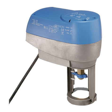
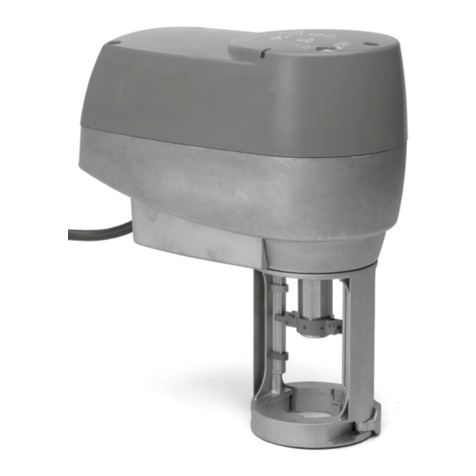
VA-747x Series
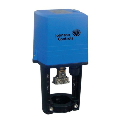
Electronic Terminal Unit Valve Actuator Part No. 14-88400-17 Rev. A
Issued 04 2010
Figure1:Dimensionsinmm
Figure 2: Mounting actuator on the valve
Figure 3: Mounting Positions
Figure 4: Cover for jumper selection
M30 x 1.5
Max 90°
Max 90°
OK OK
NO!
Figure 6: VA-7472-1001 and VA-7472-9001
Proportional Models Wirings
M
M
24 V~
common
ELECTRONIC BOARD
Blue
Red
White
common
24 V~
control signal
com 0...10V input
Red
Black
Blue
White
ELECTRONIC BOARD
(a).
Figure 5: VA-7470-1001
Floating Model Wiring
English
READ THIS INSTRUCTION SHEET AND THE SAFETY WARNINGS CAREFULLY BEFORE INSTALLING AND SAVE IT FOR FUTURE USE
VA-747x Series - Electronic Terminal Unit Valve Actuator1
This document is subject to change without notice
General Features
The VA-747x Series provides floating or proportional control in HVAC
applications.
This actuator is designed for field mounting onto VG6000 terminal unit valves.
Figure 1: Dimensions in mm
(a). Cable length 1.5 m
Mounting
Figure 2: Mounting actuator on the valve
Figure 3: Mounting positions
When mounting the actuator on a valve, please follow the instructions below:
• It is recommended that the valves be mounted upright or at angles not
greater than 90° in an easily accessible location.
• Do not mount the actuator upside down to avoid dripping water, which
could enter the housing and damage the mechanism or motor.
• Do not cover with insulating material.
• Sufficient clearance must be allowed for actuator removal (refer to the
dimension drawings).
• The valve must be installed so that the plug seats against the flow, as
indicated by the arrows on the valve.
Installation and Adjustment
Figure 4: Cover for jumper selection
Remove this cover for jumper selection
(removable only for VA-7472-9001 models)
Wiring
Wiring Diagrams
Figure 5: VA-7470-1001 Floating Model Wiring
Figure 6: VA-7472-1001 and VA-7472-9001 Proportional Models Wirings
Led Indication
After 2 minutes the motor is running, an internal timer switches off the motor.
When the signal is 0% or 100%, the timer switches on the motor every 2
hours for 2 minutes, in the signal direction.
Anti-sticking cycle (only VA-7472 models)
Every 24 hours, the actuator runs one complete cycle up and down and
returns to the control position.
Check out procedure
Before leaving the installation observe at least three complete operating
cycles to be sure that all components are functioning correctly. If not, contact
your supplier.
Autozero cycle (only on VA-7472 models)
Each time the power is switched on, the actuator performs one complete
stroke time down and after that it reaches the control position.
Repair and replacement
Field repair is not possible. If the actuator is not working properly and all
wiring is correct, the actuator should be replaced. Please check with your
nearest supplier.
IMPORTANT: the actuator stem is in completely up position from the factory.
If the actuator is powered when not mounted on the valve, be sure to return
the spindle to completely up position before mounting onto the valve.
WARNING: The electrical connections for the actuators must be
executedinaccordancewiththerelevantlegalrequirements.
In order to avoid any personal injury or damage to the
equipment or other property, always isolate the power supply
before commencing any work on the electrical wiring. In order
to avoid danger to property, it is important for the equipment to
be used solely for which it is intended.
WARNING: The integrated circuits in the actuator are sensitive
to static electricity. Take suitable precautions.
IMPORTANT: Use the Actuator only to control equipment under normal
operating conditions. Where failure or malfunction of the electric actuator
could lead to personal injury or property damage to the controlled
equipment or other property, additional precautions must be designed into
the control system. Incorporate and maintain other devices such as
supervisory or alarm system or safety or limit controls intended to warn of,
or protect against, failure or malfunction on the electric actuator.
On Power line present
Off Power line not present
Double Blinking Actuator performs an end-of-stroke
confirmation cycle or an anti-sticking cycle
Blinking The motor is running
Adjustments (jumper settings) of proportional models
VA-7472-9001 is configurable.
This is how the jumpers are positioned on the board:
Jumper in place:
Jumper removed:
Function Jumper No.
VA-7472-9001 (adjustable)
Factory setting Alternative setting
Anti-sticking 1 enabled disabled
Input control
signal 20...10 V 5...10 V 0...5 V
3
No Function 4 No function ---
Action 5 Direct (DA) Reverse (RA)
No Function 6 No function ---

6

This manual suits for next models

1

Other Johnson Controls Controllers manuals

Johnson Controls FX-PCV1617 User manual

Johnson Controls

Johnson Controls FX-PCV1617 User manual

Johnson Controls M9108 Series User manual

Johnson Controls

Johnson Controls M9108 Series User manual

Johnson Controls CVM03050 User manual

Johnson Controls

Johnson Controls CVM03050 User manual

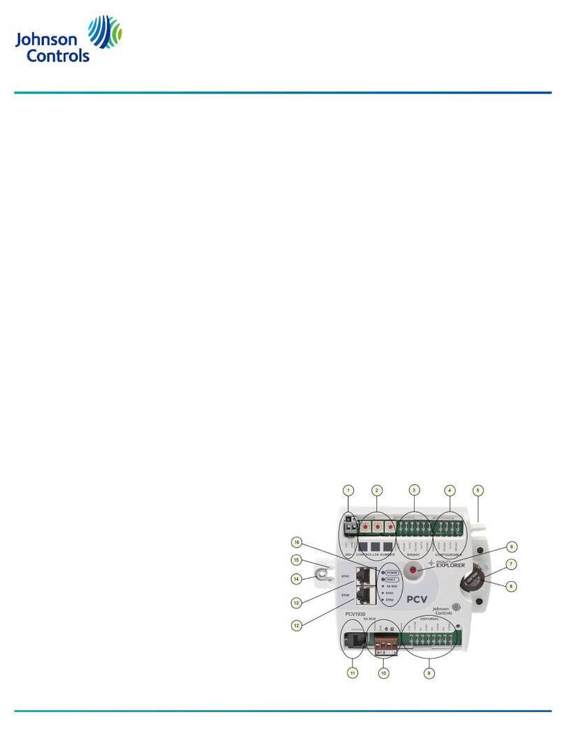
Johnson Controls FX-PCV1930 User manual

Johnson Controls

Johnson Controls FX-PCV1930 User manual

Johnson Controls LP-FX2211T-0 User manual

Johnson Controls

Johnson Controls LP-FX2211T-0 User manual

Johnson Controls UNT110-1 User manual

Johnson Controls

Johnson Controls UNT110-1 User manual

Johnson Controls FA-33-741 Series User manual

Johnson Controls

Johnson Controls FA-33-741 Series User manual

Johnson Controls M9116-GG-1N4 Series User manual

Johnson Controls

Johnson Controls M9116-GG-1N4 Series User manual

Johnson Controls EDA-8000 Manual

Johnson Controls

Johnson Controls EDA-8000 Manual

Johnson Controls FEC26 Series User manual

Johnson Controls

Johnson Controls FEC26 Series User manual

Johnson Controls M9102-GA-1S Series User manual

Johnson Controls

Johnson Controls M9102-GA-1S Series User manual

Johnson Controls tyco Power Neo HS2016 User manual

Johnson Controls

Johnson Controls tyco Power Neo HS2016 User manual

Johnson Controls FAC3613 User manual

Johnson Controls

Johnson Controls FAC3613 User manual

Johnson Controls M4-CV Series User manual

Johnson Controls

Johnson Controls M4-CV Series User manual

Johnson Controls EasyIO FW-28 User manual

Johnson Controls

Johnson Controls EasyIO FW-28 User manual

Johnson Controls VMA18 Series User manual

Johnson Controls

Johnson Controls VMA18 Series User manual

Johnson Controls York YKN2Open board Manual

Johnson Controls

Johnson Controls York YKN2Open board Manual

Johnson Controls FMS-2000C User manual

Johnson Controls

Johnson Controls FMS-2000C User manual

Johnson Controls PENN ACT2 Service manual

Johnson Controls

Johnson Controls PENN ACT2 Service manual

Johnson Controls M9132-AG -1N Series User manual

Johnson Controls

Johnson Controls M9132-AG -1N Series User manual

Johnson Controls FX-PCV Series User manual

Johnson Controls

Johnson Controls FX-PCV Series User manual

Johnson Controls FX-PCV1615 User manual

Johnson Controls

Johnson Controls FX-PCV1615 User manual

Johnson Controls METASYS ASC User manual

Johnson Controls

Johnson Controls METASYS ASC User manual

Johnson Controls FMS-2000C User manual

Johnson Controls

Johnson Controls FMS-2000C User manual

Popular Controllers manuals by other brands

Zennio MINiBOX 45v2 user manual

Zennio

Zennio MINiBOX 45v2 user manual

Samson 3381 Series Mounting and operating instructions

Samson

Samson 3381 Series Mounting and operating instructions

Mitsubishi Electric MELSEC iQ-FX5 user manual

Mitsubishi Electric

Mitsubishi Electric MELSEC iQ-FX5 user manual

RC GROUP MP2000 user manual

RC GROUP

RC GROUP MP2000 user manual

Genebre 3264 quick start guide

Genebre

Genebre 3264 quick start guide

Superior Electric STABILINE WHR5206 instructions

Superior Electric

Superior Electric STABILINE WHR5206 instructions

Satel MTX-300 manual

Satel

Satel MTX-300 manual

AUMA PROFOX PF-M100X manual

AUMA

AUMA PROFOX PF-M100X manual

Viconics COV-PIR-FCU-C-5000 install guide

Viconics

Viconics COV-PIR-FCU-C-5000 install guide

HomePro ZDW120 quick start guide

HomePro

HomePro ZDW120 quick start guide

Abus wAppLoxx Pro Installation and operating instructions

Abus

Abus wAppLoxx Pro Installation and operating instructions

Daikin FWEC2T Installation and use manual

Daikin

Daikin FWEC2T Installation and use manual

Metronix ARS 2302 product manual

Metronix

Metronix ARS 2302 product manual

Atlas Copco POWER FOCUS 6000 quick start guide

Atlas Copco

Atlas Copco POWER FOCUS 6000 quick start guide

Martinsound MonitorMAX user manual

Martinsound

Martinsound MonitorMAX user manual

Jung Smart Pilot 10 manual

Jung

Jung Smart Pilot 10 manual

Evco EVJ254 manual

Evco

Evco EVJ254 manual

esera automation 11319 operating instructions

esera automation

esera automation 11319 operating instructions

manuals.online logo
manuals.online logoBrands
  • About & Mission
  • Contact us
  • Privacy Policy
  • Terms and Conditions

Copyright 2025 Manuals.Online. All Rights Reserved.