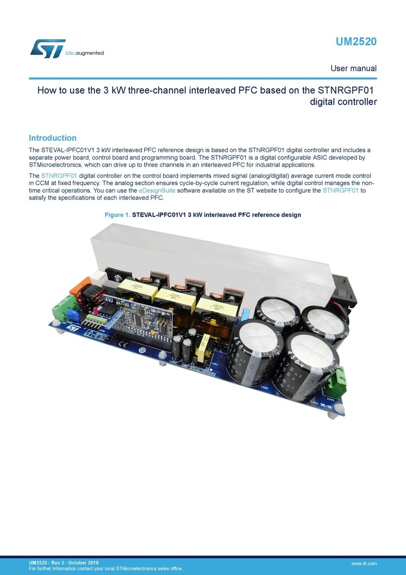
ST STEVAL-ESC002V1 User manual

Introduction
The STEVAL-ESC002V1 electronic speed controller (ESC) reference design can be used with different kind of drones, from
small racing ones to bigger light drones used for surveying and any 3-phase BLDC application requiring a compact form factor
and high speed rotation performance.
Together with the STSW-ESC002V1 firmware package, it implements a sensorless voltage mode six-step driving.
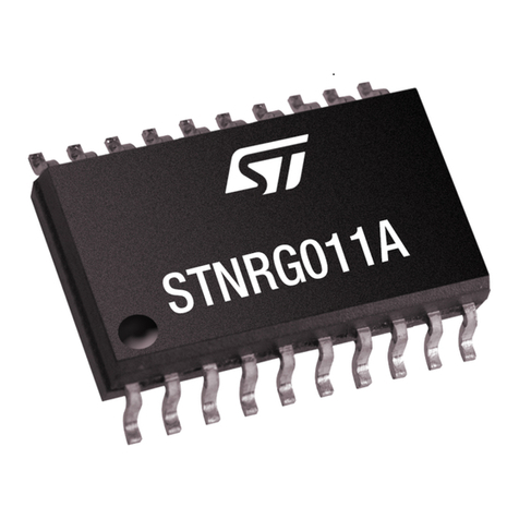
The board is based on the STSPIN32F0A advanced 3-phase brushless motor controller that embeds an ARM® Cortex®-M0
processor, voltage regulators, signal conditioning circuitry and gate drivers in a small 7x7 mm2 QFN package.
Power stage is based on the low resistance (2.8 mΩ) and high speed STL140N6F7 MOSFETs, designed in STripFET™ F7
technology and able to deliver up to 20 A of continuous current.
Figure 1. STEVAL-ESC002V1 reference design: top view with bulk capacitors mounted
Getting started with the STEVAL-ESC002V1 electronic speed controller reference
design
UM2518
User manual
UM2518 - Rev 1 - December 2018
For further information contact your local STMicroelectronics sales office.
www.st.com

1Safety precautions
Warning:
Some of the components mounted on the board could reach hazardous temperature during
operation.
While using the board:
• Do not touch the components
• Do not cover the board
• Do not put the board in contact with flammable materials or with materials releasing smoke when heated
After operation, allow the board to cool down before touching it.
UM2518
Safety precautions
UM2518 - Rev 1 page 2/19

2Main features and target applications
The STEVAL-ESC002V1 reference design features:
• Based on the STSPIN32F0A:
– Extended operating voltage from 6.7 to 45 V
– Three-phase gate drivers with 600 mA sink/source capability and integrated bootstrap diode
– 32-bit ARM® Cortex®-M0 core operating up to 48 MHz clock frequency
– 4-kByte SRAM and 32-kByte Flash memory with option bytes used for write/readout protection
– 3.3. V buck converter with overcurrent, short-circuit, and thermal protection
– 12 V LDO linear regulator with thermal protection
– 3 rail-to-rail operation amplifiers for signal conditioning
– Comparator for overcurrent protection with programmable threshold
– UVLO protection on each power supply
– Extended temperature range: -40 to +125 °C
• Designed for sensorless six-step driving with BEMF sensing through operational amplifiers embedded in the
STSPIN32F0A
• 2S to 6S LiPo battery pack
• Output current up to 20 ARMS
• Overcurrent protection
• Battery voltage sensing
• UART and I²C interfaces
• RGB LED
• SWD interface to program and debug
• Embedded bootloader
• Very compact and light design: 25 x 40.5 mm PCB size
• RoHS and WEEE compliant
The STEVAL-ESC002V1 reference design mainly targets light drones for professional and recreational purposes,
and any 3-phase brushless application requiring a high speed rotation performance.
UM2518
Main features and target applications
UM2518 - Rev 1 page 3/19

3Hardware overview
The STEVAL-ESC002V1 drives a single three-phase brushless motor.
Figure 2. STEVAL-ESC002V1 components (top view)
Battery positive input PWM input
RGB LED
SWD connector
UART/I2C
TP1, TP2, TP3
BEMF sensing
outputs
Positive lead of the bulk capacitors
Bulk capacitors
(to be mounted)
Battery negative input
Bootloader connector
Power output W
Power output V
Power output U
LMV321L
TP6, TP7
PA5 and PA7 debug GPIOs
To the motor
To the motor
To the motor
To the battery
To the battery
STSPIN32F0A
Figure 3. STEVAL-ESC002V1 components (bottom view)
Bypass capacitors
STL140N6F7 Power MOSFETs
Bulk capacitors
(to be mounted)
Shunt resistor
(overcurrent protection and current sensing)
Negative lead of the bulk capacitors
UM2518
Hardware overview
UM2518 - Rev 1 page 4/19

Table 1. Test points and connectors
Connector/ Test point Pin Signal GPIO Description
CON1 1 OUTU Power output U.
It has to be connected to one of the motor phases
CON2 1 OUTV Power output V
It has to be connected to one of the motor phases
CON3 1 OUTW Power output W
It has to be connected to one of the motor phases
CON4 1 VBUS Supply voltage
It has to be connected to the battery positive lead
CON5 1 GND Ground
It has to be connected to the battery negative lead
J1
1 SWD_CLK PA14 SWD interface clock signal
2 GND Ground
3 SWD_IO PA13 SWD interface data signal
J2
1 TX/SCL PB6
PB6 GPIO:
• UART interface TX signal
• I²C interface SCL signal
2 RX/SDA PB7
PB7 GPIO:
• UART interface RX signal
• I²C interface SDA signal
J3
1 TX PA14 UART TX signal when the bootloader is running
2 RX PA15 UART RX signal when the bootloader is running
3 BOOT0 Boot mode enabler (force high at power-up/reset)
TP1 1 OP3O PF1 BEMF comparator output (phase U)
TP2 1 OP2O PF0 BEMF comparator output (phase V)
TP3 1 OP1O PB1 BEMF comparator output (phase W)
TP4 1 PWM_IN PA6 Ground
It has to be connected to the FCU PWM output
TP5 1 GND Ground
It has to be connected to the FCU PWM output
TP6 1 PA5 PA5 To debug
TP7 1 PA7 PA7 To debug
UM2518
Hardware overview
UM2518 - Rev 1 page 5/19

4Setup
Step 1. Mount the bulk capacitors (included in the package) on the dedicated pads as shown in Figure 1 and
Figure 2
Capacitors must be mounted as follows: negative lead (short one) on the bottom side and positive lead
(long one) on the top side.
Warning:
Do not operate without the bulk capacitors properly mounted to not damage the board and the
battery.
Step 2. Solder the motor phases to the board as shown in Figure 1.
Color sequence is not important and affects only the rotation direction.
Step 3. Solder the FCU PWM output to the board as indicated in Figure 1: positive on TP4 (round pad) and
negative on TP5 (square pad).
Figure 4. STEVAL-ESC002V1 PWM input from FCU connection details
PWM
Step 4. Connect the board to the battery or to a DC power supply as indicated in Figure 1 (supply range is from
2S to 6S).
Step 5. Supply the board.
Step 6. Program the board through the SWD interface as described in the following section.
The board is ready to use.
4.1 Programming the board
The board is programmed through the microcontroller SWD interface. J1 and the included cable provide access to
the SWD interface.
UM2518
Setup
UM2518 - Rev 1 page 6/19

Figure 5. STEVAL-ESC002V1 SWD connection details
Included connector
SWCLK
GROUND
SWDIO
When the board is connected to the SWD programmer, you can program it in two ways.
Step 1. Write the binary included in the STSW-ESC002V1 firmware package or
Step 2. Compile and download the project included in the STSW-ESC002V1 firmware package (IAR
Embedded Workbench for ARM 8.22).
UM2518
Programming the board
UM2518 - Rev 1 page 7/19

5Board PWM flowchart and interface parameters
After the setup procedure (see Section 4 ), the board is operative.
The STSW-ESC002V1 firmware monitors the pulse duration of the PWM input setting according to the voltage
applied to the motor.
Note: The firmware does not monitor the PWM signal frequency. The algorithm considers only the duration of the
positive pulses.
The STEVAL-ESC002V1 default behavior is described below.
1. At power-up the motor is stopped.
2. The ESC waits for at least BSP_BOARD_IF_TIMx_ARMING_VALID_TON pulses before arming (that is
allowing the motor driving) the board. Even if the board is armed, the motor is not driven yet.
3. When at least BSP_BOARD_IF_TIMx_START_VALID_TON pulses longer than
BSP_BOARD_IF_TIMx_MIN_SPEED_TON_US μs are detected, the motor is started.
4. When more than BSP_BOARD_IF_TIMx_STOP_VALID_TON pulses shorter than
BSP_BOARD_IF_TIMx_MIN_SPEED_TON_US μs are detected, the motor is stopped.
5. When the motor is running, the speed is proportional to the PWM pulse duration. The maximum speed is
achieved when the pulse duration is BSP_BOARD_IF_TIMx_MAX_SPEED_TON_US μs.
6. If no pulses are detected for more than BSP_BOARD_IF_TIMx_STOP_MS ms, the motor is stopped and the
board is disarmed, that is motor driving is not allowed.
UM2518
Board PWM flowchart and interface parameters
UM2518 - Rev 1 page 8/19

Figure 6. STEVAL-ESC002V1 default behavior: PWM interface flowchart
Disarmed
Stop
1500 ms timeout
expired?
Update speed
NO
Stop count = 0
expired?
NO
> Min. pulse
Stop Count = 0
Pulse detected
NOYES
YES
NO
YES
Arm. Count ++
Start
NO
NO
NO
Armed
Pulse detected
> Min. pulse Stop Count ++
Pulse detected
YES
1500 ms timeout
expired?
NO
Arm. Count = 0
YES
YES
Start Count > 10
Stop Count > 1000
1500 ms timeout
Start Count ++
Start Count = 0
Arm. Count > 10
NO
NO
NO
YES
YES
YES
YES
YES
The default values for the PWM monitoring code are listed in the following table.
UM2518
Board PWM flowchart and interface parameters
UM2518 - Rev 1 page 9/19

Table 2. PWM interface parameters
Parameter Description Default
BSP_BOARD_IF_TIMx_STOP_MS No-PWM timeout in ms 1500
BSP_BOARD_IF_TIMx_ARMING_VALID_TON Number of valid PWM pulses (any duration) arming the board 10
BSP_BOARD_IF_TIMx_START_VALID_TON Number of PWM pulses above minimum duration starting the
motor 10
BSP_BOARD_IF_TIMx_STOP_VALID_TON Number of PWM pulses below minimum duration starting the
motor 1000
BSP_BOARD_IF_TIMx_MIN_SPEED_TON_US Minimum pulse duration (corresponding to minimum speed) in
μs 1060
BSP_BOARD_IF_TIMx_MAX_SPEED_TON_US Maximum pulse duration (corresponding to maximum speed) in
μs 2084(1)
1. The value is calculated according to the following formula (BSP_BOARD_IF_TIMx_MIN2MAX_BITS = 10):
BSP_BOARD_IF_TIMx_MIN_SPEED_TON_US + 2BSP_BOARD_IF_TIMx_MIN2MAX_BITS. It is not possible to set an arbitrary
value: the range changes according to the BSP_BOARD_IF_TIMx_MIN2MAX_BITS parameter.
UM2518
Board PWM flowchart and interface parameters
UM2518 - Rev 1 page 10/19

6Schematic diagrams
Figure 7. STEVAL-ESC002V1 circuit schematic (1 of 3)
680nF
330nF PA0
20
OP3P
PB7
OP2O
4PF0
BOOT0 42
43
100nF OP2O
1n
PA1
LSU
HSV
L1 22µH
LSW
PA6
17
PA13
HSU
C1
OP1P
PB1
38
PA15
29
31
C5
OP2N
3
VDDA
OP1N
OP3P 45
37
PA14
OP3O
PB6
C7
PA4
HSW 25
OP2P
10
PA0
11
PF0
6
OUTV
VDD
18
PB1
19
39K
HSW
OUTV
OP2N
VDD 48
D1
23
BLUE
RX
TX/SWCLK
SWDIO
VREG
PA6
680nF
OP3N
VM
24 OCCOMP
PA4
PA7 RESERVED
GND 44
PF1
5
PA7
47µF
RED
GREEN
OUTW 26
22
OP1P
VDD
EPAD
PA5
C9
C6
15
PA5
16
100nF
R1
C10
SW
9
OUTW
OP3N 46
OP1N
OP1O
VREG12
7
12
PA2
13
30
OUTU
39
PB6 40
OP2P
STSPIN32F0A
2
PA14
VDD
33
35
C3
NRST
VM
8
36
HSU
VBOOTV
LSV 32
1
STPS0560Z
C8
OUTU
PA3
14
100nF
U1
34
LSU
41
HSV
PA1
ZCV
ZCU
PA15
ZCW
CURR
PWM_IN
VBUS
49
680nF
PF1
25V
PA13
TESTMODE
OP1O
21
VBOOTU
PA2
PA3
BOOT0
OCCOMP
C2
SRN3015-220M
10µF
LSV
PB7
C4
27
VBOOTW
LSW 28
OP3O 47
Figure 8. STEVAL-ESC002V1 circuit schematic (2 of 3)
CON1
ERJMP3PF1M0U
R11
1k
8
PF0
4
LMV321L
TP3
1in+
2
LSU
3
PAD
1
10nF
R22
3
LSV
Q6
8
PAD
1
5
TP1
R9
8
4
U2
Q5
25R
STL140N6F7
VDD
1k
2
OUTW
VBUS
R6 25R
4
2
R16
1k
VBUS
7
STL140N6F7
7
3
6
PAD
1
+
-
+
10k
5
Q1
25R
8
OP3P
OP1P
HSU
10k
Q3
R14
25R
HSV
5
1
STL140N6F7
1
PF1
VCC-
CON3
R3
OUTU
Panasonic
+
-
-
VBUS
7
25R R4
2
R10
470k
LSW
R5
R12
1
Q2
OP2P
R20
STL140N6F7STL140N6F7
2
5
8
3
2
6
VDD
10k
OP2N
4
4
1k
OUTV
R7
VCC+
6
R2
PB1
OP1N
OP3O
7
10k
6
Q4
5
R21
1k
1
1
6
R23
OP1O
1
58
in-
5
10k10k
out
6
C13
TP2
7
0.001
CON2
R171k
R13
10nF
OP2O
PA4
R19
3
R15
3
OCCOMP
R18
3
OP3N
4
C11
10k
C12100nF
2
24k
7
HSW
STL140N6F7
4
R8
25R
UM2518
Schematic diagrams
UM2518 - Rev 1 page 11/19

Figure 9. STEVAL-ESC002V1 circuit schematic (3 of 3)
330
1
2
+
WARNING!
The board is provided with bulk
capacitors C21 and C22 not mounted.
Mount the bulk capacitors on the board before using it.
1
2
3
PA0
TP6
POWER CONTACT
C19
R28220
PB6
R2939
PA2
CON3
C14
KB
2
N1
PA6
PA3
POWER CONTACT
CON2
PA15
ASMB-MTB0-0A3A2
KG
3
KR
4
RGB LED control
C20
4.7µF
SM03B-SRSS-TB
C17
Debug GPIOs
Bootloader
PWM input
SWD CLK
C22
TP5
R26
Power supply
4.7µF
1%
C18
+
1
CON4
4.7nF
VBUS
BOOT0
C21
J2
LD1
VBUS
Feedback
SWD prog.
TP7
VBUS
VM
220µF/63V
C16
+
-
PA1
PA5
PB7 PA7
C15
J1
A
1
PA14
PA13
1
2
3
R25
33k
SWD IO
J3
220µF/63V
Alternative order code
Panasonic ECA1JM221
WE 2465850
SH3-SS5-28150
SHR-03V-S-B
Connector:
Pre-crimped wire 150 mm
Housing 3 poles 1 mm
SW CON
1%
TP4
connector
VDD
PA14
4.7µF
N2
4.7µF 4.7µF
CON5
1
4.7µF
VBUS
R2739
R24
470k
UM2518
Schematic diagrams
UM2518 - Rev 1 page 12/19

7Bill of materials
Table 3. STEVAL-ESC002V1 bill of materials
Item Q.ty Ref. Part / Value Description Manufacturer Order code
13CON1, CON2,
CON3
RECT_PAD257R200D
35_43 Connectors Any -
2 2 CON4, CON5 pad221hole35_43 Connectors Any -
34C1, C3, C10,
C12
100 nF 50 V ±10%
C0603 X7R Capacitors Any -
4 1 C2 10 µF 25 V ±10%
C0805 X7R Capacitor Any -
5 3 C4, C6, C7 680 nF 16 V ±10%
C0603 X7R Capacitors Any -
6 1 C5 1 nF 50 V ±10%
C0603 X7R Capacitor Any -
7 1 C8 330 nF 50 V ±10%
C0603 X7R Capacitor Any -
8 1 C9 47 µF 6.3 V ±20%
C0805 X5R Capacitor Any -
9 2 C11, C13 10 nF 50 V ±10%
C0603 X7R Capacitor Any -
10 6 C14, C15, C16,
C17, C18, C19
4.7 µF 50 V ±15%
C0805 X5R Capacitors Any -
11 1 C20 4.7 nF 50 V ±10%
C0603 X7R Capacitor Any -
12 2 C21, C22 220 µF 63 V ±20%
D400p200-padsmt
Aluminium
capacitors
Wurth
Electronics 860020775019
Panasonic ECA1JM221
13 1 D1 STPS0560Z SOD-123 Power Schottky
rectifier ST STPS0560Z
14 1 J1 SW CON SM03B-
SRSS-TB Jumper JST SM03B-SRSS-TB
15 1 J2 CON2 CON_2-
pitch49_87-38x75 Jumper Any -
16 1 J3 CON3 CON_3-
pitch49_87-38x75 Jumper Any -
17 1 LD1 PLCC-4 RGB LED Avago ASMB-MTB0-0A3A2
18 1 L1 22 µH 0.6 A ±20%
SRN3015 Fixed inductor Bourns SRN3015-220M
19 2 N1, N2 SHORT Any -
20 6 Q1, Q2, Q3,
Q4, Q5, Q6
STL140N6F7
PFLAT_6X5-8LEADS
N-channel 60
V, 0.0024 Ohm
typ., 140 A
STripFET F7
Power
MOSFET in a
PowerFLAT
5x6 package
ST STL1401N6F7
21 1 R1 39 K 1/10 W ±5%
R0603 Resistor Any -
UM2518
Bill of materials
UM2518 - Rev 1 page 13/19

Item Q.ty Ref. Part / Value Description Manufacturer Order code
22 6 R2, R3, R4,
R5, R6, R7
25 R 1/10 W ±5%
R0603 Resistors Any -
23 3 R8, R9, R10 10 k 1/10 W ±1%
R0603 Resistors Any -
24 3 R11, R17, R18 1 k 1/10 W ±5% R0603 Resistors Any -
25 3 R12, R14, R16 10 k 1/10 W ±1%
R0603 Resistors Any -
26 1 R13 1 m 2 W ±1% R2010 Resistor Panasonic ERJMP3PF1M0U
27 1 R15 470 k 1/10 W ±5%
R0603 Resistor Any -
28 1 R19 10 k 1/10 W ±5%
R0603 Resistor Any -
29 3 R20, R21, R22 1 k 1/10 W ±1% R0603 Resistors Any -
30 1 R23 24 k 1/10 W ±5%
R0603 Resistor Any -
31 1 R24 470 k 1/8 W ±1%
R0603 Resistor Any -
32 1 R25 33 k 1/8 W ±1% R0603 Resistor Any -
33 1 R26 330 1/10 W ±5%
R0603 Resistor Any -
34 2 R27, R29 39 1/10 W ±5% R0603 Resistors Any -
35 1 R28 220 1/10 W ±5%
R0603 Resistor Any -
36 5 TP1, TP2, TP3,
TP6, TP7
TP-SMD-
diam0_762mm TP-
D30
Test points Any -
37 1 TP4 TP-SMD-diam1_27mm
TP-D50 Test point Any -
38 1 TP5
TP-SMD-
square1_27mm
TP-50x50
Test point Any -
39 1 U1
STSPIN32F0A
VFQFPN48L7x7x1-49
P
Advanced
BLDC
controller with
embedded
STM32 MCU
ST STSPIN32F0A
40 1 U2 LMV321L SOT23-5L
Low-power,
general-
purpose
operational
amplifier
ST LMV321LILT
41 3 Pre-crimped
wire JST SH3-SS5-28150
42 1 Connector
housing JST SHR-03V-S-B
UM2518
Bill of materials
UM2518 - Rev 1 page 14/19

Revision history
Table 4. Document revision history
Date Version Changes
17-Dec-2018 1 Initial release.
UM2518
UM2518 - Rev 1 page 15/19

Contents
1Safety precautions.................................................................2
2Main features and target applications ..............................................3
3Hardware overview ................................................................4
4Setup..............................................................................6
4.1 Programming the board .........................................................6
5Board PWM flowchart and interface parameters ....................................8
6Schematic diagrams ..............................................................11
7Bill of materials...................................................................13
Revision history .......................................................................15
UM2518
Contents
UM2518 - Rev 1 page 16/19

List of figures
Figure 1. STEVAL-ESC002V1 reference design: top view with bulk capacitors mounted ........................1
Figure 2. STEVAL-ESC002V1 components (top view) ................................................4
Figure 3. STEVAL-ESC002V1 components (bottom view) .............................................4
Figure 4. STEVAL-ESC002V1 PWM input from FCU connection details ...................................6
Figure 5. STEVAL-ESC002V1 SWD connection details ...............................................7
Figure 6. STEVAL-ESC002V1 default behavior: PWM interface flowchart ..................................9
Figure 7. STEVAL-ESC002V1 circuit schematic (1 of 3).............................................. 11
Figure 8. STEVAL-ESC002V1 circuit schematic (2 of 3).............................................. 11
Figure 9. STEVAL-ESC002V1 circuit schematic (3 of 3).............................................. 12
UM2518
List of figures
UM2518 - Rev 1 page 17/19

List of tables
Table 1. Test points and connectors .............................................................5
Table 2. PWM interface parameters ............................................................ 10
Table 3. STEVAL-ESC002V1 bill of materials...................................................... 13
Table 4. Document revision history ............................................................. 15
UM2518
List of tables
UM2518 - Rev 1 page 18/19

IMPORTANT NOTICE – PLEASE READ CAREFULLY
STMicroelectronics NV and its subsidiaries (“ST”) reserve the right to make changes, corrections, enhancements, modifications, and improvements to ST
products and/or to this document at any time without notice. Purchasers should obtain the latest relevant information on ST products before placing orders. ST
products are sold pursuant to ST’s terms and conditions of sale in place at the time of order acknowledgement.
Purchasers are solely responsible for the choice, selection, and use of ST products and ST assumes no liability for application assistance or the design of
Purchasers’ products.
No license, express or implied, to any intellectual property right is granted by ST herein.
Resale of ST products with provisions different from the information set forth herein shall void any warranty granted by ST for such product.
ST and the ST logo are trademarks of ST. All other product or service names are the property of their respective owners.
Information in this document supersedes and replaces information previously supplied in any prior versions of this document.
© 2018 STMicroelectronics – All rights reserved
UM2518
UM2518 - Rev 1 page 19/19
Table of contents
Other ST Controllers manuals

ST
ST ST5-Q User manual

ST
ST STEVAL-IHM037V1 User manual

ST
ST EVLSPIN32G4-ACT User manual

ST
ST STM32W-SK User manual

ST
ST STM32MP13-ETZPC User manual

ST
ST STM32F101xx series Owner's manual

ST
ST ST-PMC1 User manual

ST
ST STEVAL-IAS001V1 User manual

ST
ST Sitronix ST7038 User manual

ST
ST STEVAL-A6983NV1 User manual
Popular Controllers manuals by other brands

maxon motor
maxon motor EPOS2 Module 36/2 Hardware reference

MegaPoints Controllers
MegaPoints Controllers AutoSignal user guide

NXP Semiconductors
NXP Semiconductors PN7150 user manual

Regin
Regin REGIO RC-DTO instructions

Honeywell
Honeywell HVC0002 owner's guide

IPC
IPC D1086 Installing, operating & maintaining