Johnson Controls YORK ROOFTOP ACTIVA 017 / 022 User manual

Energy recovery system for
ROOFTOP ACTIVA 017 / 040
Options and accessories, Installation manual
Ref.: N-40450_EN 0714

Index
1Energy recovery system for ROOFTOP ACTIVA 017 / 040.....................................................1
1.1 General Description.................................................................................................................2
1.2 General dimensions.................................................................................................................3
1.3 Operation.................................................................................................................................5
1.3.1 Operating diagram....................................................................................................................6
1.4 Assembly and handling............................................................................................................7
1.5 Installation................................................................................................................................8
1.6 Electrical connections............................................................................................................12
1.7 Maintenance...........................................................................................................................14
1.7.1 Enthalpy wheel.......................................................................................................................14
1.8 Electrical specifications..........................................................................................................15
1.9 Wiring diagram.......................................................................................................................16
1.10 Efficiency and recovered load................................................................................................17
1.10.1 Efficiency................................................................................................................................17
1.10.2 Recovered load at sea level...................................................................................................18
1.10.3 Recovered load correction factor, according to the elevation from sea level.........................23
1.11 Tempered air (TA) and indoor coil entering air (EA) temperatures........................................24
Index
i

1
Energy recovery system for ROOFTOP
ACTIVA 017 / 040

1.1 General Description
Depending on the size of the Rooftop unit, there are two models of energy recovery system, with renewal
airflow in accordance with the following table:
Model Airflow rate
[m3/h]
017 / 022 1000 ‑ 1400 ‑ 1800 ‑ 2200
032 / 040 1800 ‑ 2200 ‑ 2800 ‑ 3400
The renewal airflow required must be indicated at the time the order is placed.
Otherwise, the energy recovery is supplied adjusted to the following airflows:
• 017: 1800 m3/h
• 022: 2200 m3/h
• 032: 2800 m3/h
• 040: 3400 m3/h
NOTE
These renewal airflows correspond to a 46 ÷ 53 % of the rated airflow of the Rooftop unit (see tables in
section Tempered air (TA) and indoor coil entering air (EA) temperatures, see on page 24).
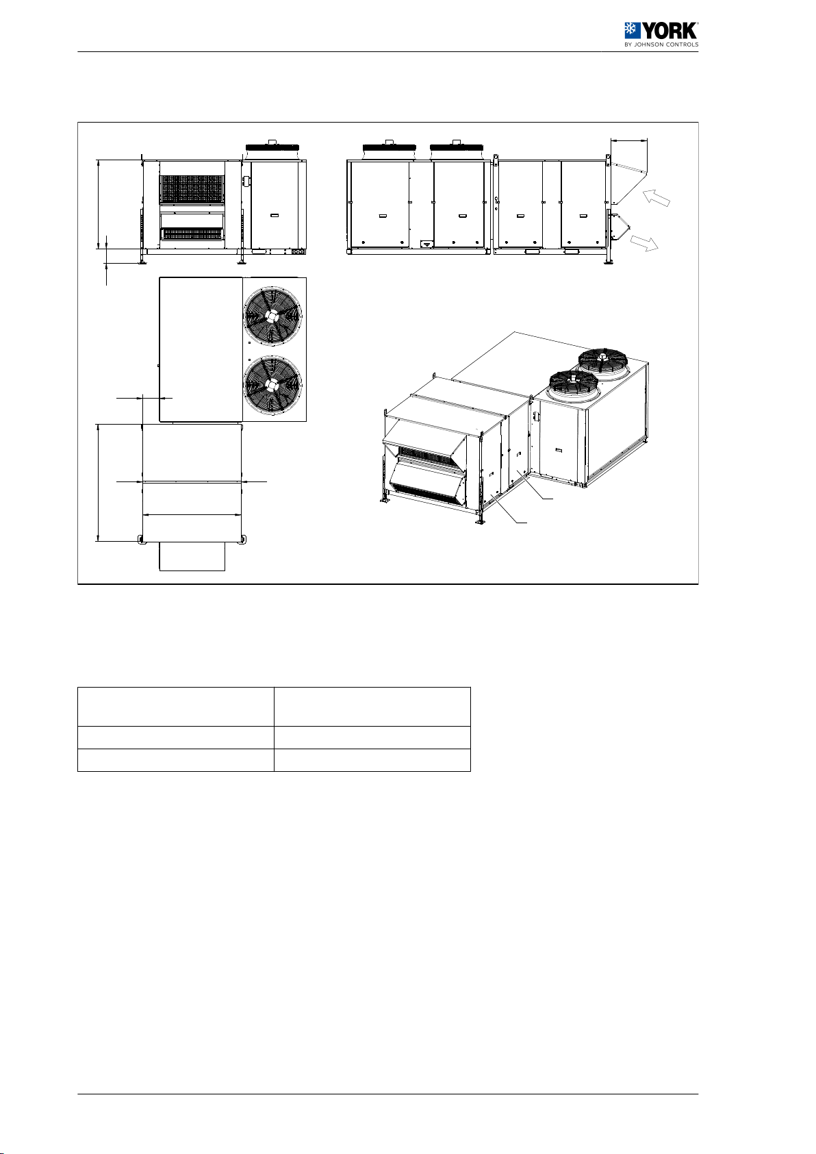
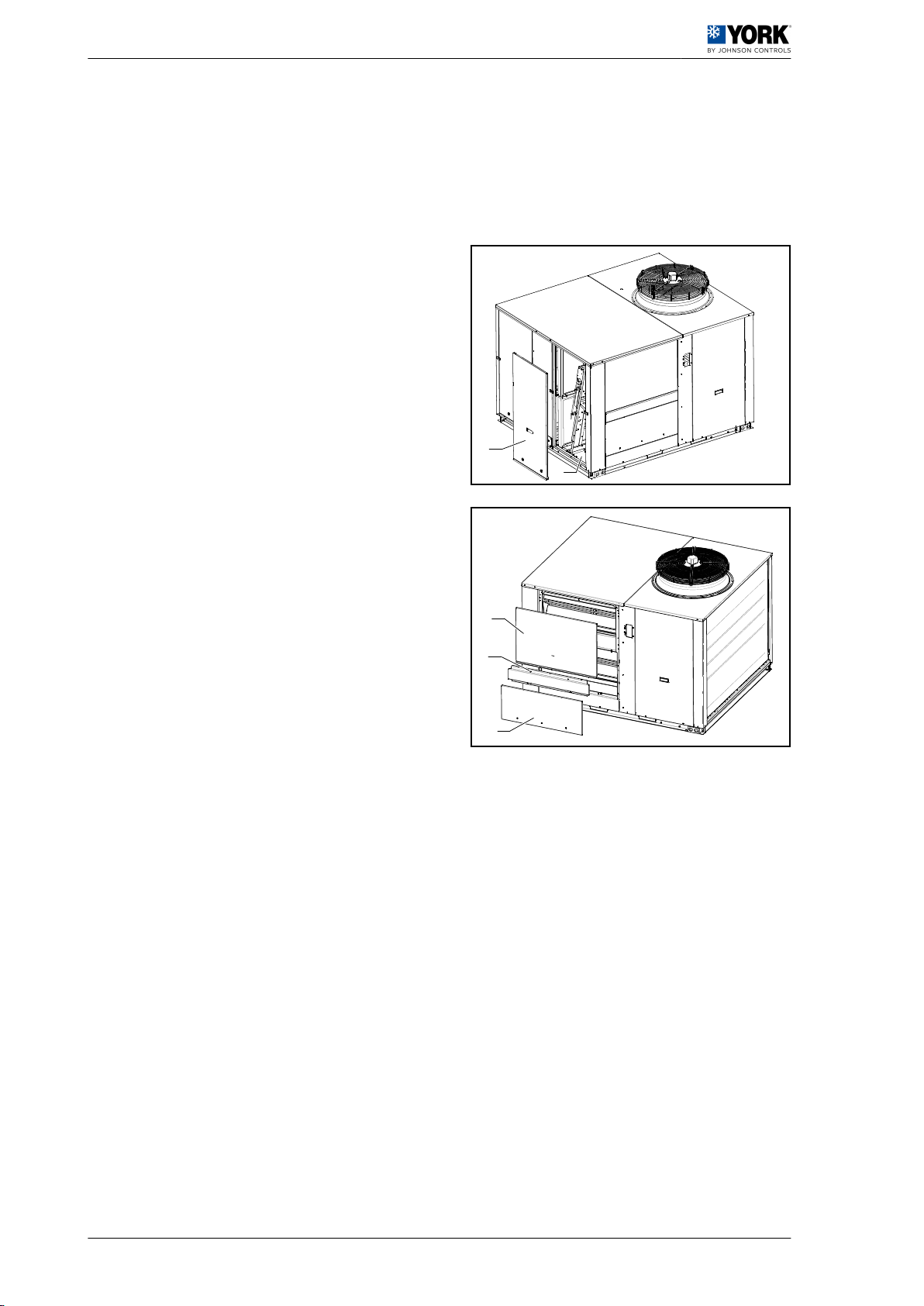
The energy recovery system is used directly coupled to the side of the Rooftop Activa units and includes
the Economiser and indoor air quality probe options.
NOTE
Only the vertical return air duct can be connected, at the bottom of the Rooftop unit.
Features:
• Rotating sectorised enthalpy wheel energy recovery system and rated diameter 30" (Models 017 /
022) and 36" (Models 032 / 040).
• Radial centrifugal fan, motor with integrated EC technology, controlled by differential pressure probe,
ensuring a constant renewal flow.
• Motor protection rating IP54 and insulation class F.
• Bypass damper for economiser mode operation.
• Rain protection (Rainhood) with drip filters on the air intake.
• Barometric damper on the exhaust air.
• G4 air filters, as standard on both sides of the enthalpy wheel. F6 and F7 optional.
• Height-adjustable support legs.
• All cabinet panels are fitted with heat insulation on the inside.
The enthalpy wheel provides substantial savings by reducing the demand for energy. It is ideal for areas
with high or low temperatures and areas with a high level of humidity. Also for areas with a very low level
of humidity, in buildings with a humidifying system, as the humidity is recovered from the exhaust air and
re-introduced into the building.
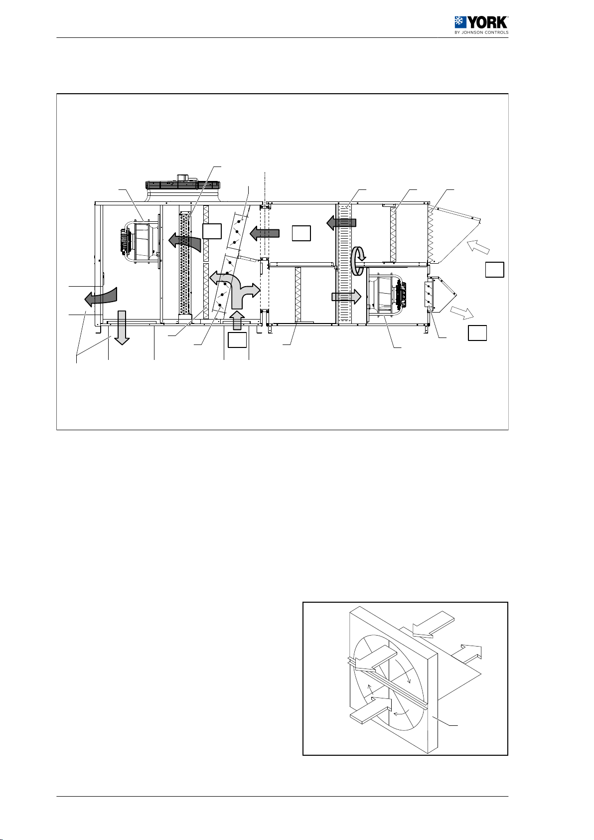
Air leakage and bleed sector
Many rotating recovery systems are fitted with a bleed sector when this is often not necessary. The bleed
sector minimises leaks between the exhaust airflow to that of the intake airflow by diverting a portion of
the latter to the exhaust flow through the separator between the two.
This is only necessary in cases of industrial applications where the exhaust air carries contaminants. As
a result, the air volume to be moved is 15-20% higher to ensure the required renewal flow, with the
subsequent increase in power required in the fan motor.
In residential air conditioning, the renewal air maintains an acceptable air quality and there are no
concentrated contaminants to be taken into account.
1Energy recovery system for ROOFTOP ACTIVA 017 / 040
1.1 General Description
2

The exhaust air leakage to that of the intake air in this energy recovery system is at a value of less than
5%. The resulting cost of moving this volume of air is much lower than in the case of a bleed sector. Do
not use this energy recovery system in industrial applications with concentrated contaminants.
1.2 General dimensions
Energy recovery AR – 017 / 022
216
462
4
3
1208
315
MAX.
1533
1255
600 1000
AB
1
2
1. Exhaust side filter access 4. Air intake
2. Intake side filter access A. and B. Minimum clearance
3. Exhaust air
Energy recovery system for ROOFTOP ACTIVA 017 / 040 1
General dimensions 1.2
3

Energy recovery AR – 032 / 040
216
462
4
3
1232
315
MAX.
1533
1505
600 1200
AB
1
2
1. Exhaust side filter access 4. Air intake
2. Intake side filter access A. and B. Minimum clearance
3. Exhaust air
Model Weight
[kg]
017 / 022 307
032 / 040 390
1 Energy recovery system for ROOFTOP ACTIVA 017 / 040
1.2 General dimensions
4

1.3 Operation
The enthalpy wheel is centred between the outdoor intake airflow and the exhaust airflow. It is the only
truly self-cleaning system, as during rotation the airflow moves in opposite directions over each half of
the wheel surface.
When the rotation movement is at 60 r.p.m., the wheel surface absorbs the sensible and latent energy
from the side with the highest temperature and transfers it to the side with the lowest temperature, thus
making the exchange of airflow between both sides. During a summer cycle, the rotation of the wheel
transfers heat and outdoor air humidity (renewal) to the exhaust air.
During a winter cycle, the process is the opposite, transferring heat and exhaust air humidity to the
renewal air.
Where there is no kind of demand (HVAC or ventilation) and the air quality is correct, the unit remains
at a standstill.
If continuous ventilation mode is selected and the air renewal selected is less than 30%, only the
Rooftop unit indoor fan will run.
If air renewal of over 30% is selected, the two fans (unit indoor and exhaust) will run and the enthalpy
wheel will turn. In this case, and when the air quality is incorrect, air renewal will be as per the airflow
indicated in the table of
General Description, see on page 2
.
When there is a demand for cold (outdoor air not favourable) or a demand for heat and the air quality is
correct, the compressors or heat support and the unit's indoor fan will start up. If air renewal of over 30%
is selected, the exhaust fan and the enthalpy wheel will also run, thus making the exchange and recovery
of energy. In this case, and when the air quality is incorrect, air renewal will be as per the airflow indicated
in the table of
General Description, see on page 2
.
During operation in economiser mode (Free cooling) the enthalpy wheel will stop turning, the air bypass
damper will open and the two fans continue to run to (unit indoor and exhaust). In this case, no exchange
or recovery of energy is produced, and the supply and exhaust airflow balance is maintained. If the
outdoor air intake is insufficient to meet the demand, a compressor will start.
Energy recovery system for ROOFTOP ACTIVA 017 / 040 1
Operation 1.3
5

1.3.1 Operating diagram
RA
B A
SA
OA
TA
10
1
2
3
5
6
4
EA
9
15
141013
7
8
11
10
12
AEnergy recovery system 8 Indoor supply fan
B Rooftop 9 Exhaust fan
1 Supply air, side or down ducted 10 Air filters
2 Return air, downflow (RA) 11 Economiser, outdoor air damper
3 Outdoor air (OA) 12 Economiser, return air damper
4 Exhaust air (SA) 13 Enthalpy wheel, with bypass damper
5 Tempered air (TA) 14 Aluminium mesh filter
6 Indoor coil entering air (EA) 15 Barometric damper
7 Indoor coil
2Return air
(RA) 5Tempered
air (TA)
3Outdoor air
(OA) 11 Enthalpy
wheel
4Exhaust air
(SA)
2
RA
5
TA
3
OA
4
SA
11
1 Energy recovery system for ROOFTOP ACTIVA 017 / 040
1.3 Operation
6

1.4 Assembly and handling
The Rooftop unit must be installed on a Roofcurb type mounting base, or similar.
The energy recovery system is fitted with lugs for
hoisting and handling during the fitting process -A-. To
do so:
1. Loosen the screw slightly.
2. Turn the lug to the correct position.
3. Tighten the screw.
It also has height-adjustable support legs on the side
opposite to connection to the Rooftop unit -B-.
B
A
Energy recovery system for ROOFTOP ACTIVA 017 / 040 1
Assembly and handling 1.4
7

1.5 Installation
Installation process
(First make sure the Economiser and air quality probe options are installed in the Rooftop unit)
1. Disconnect the power supply to the Rooftop unit.
2. Remove the economiser access panel -A-.
3. Remove the side panels -B- and -C- and separator
-D-.
4. Remove the return air cover on the base -E-.
A
E
C
D
B
1Energy recovery system for ROOFTOP ACTIVA 017 / 040
1.5 Installation
8

5. Place the frame of the support -F- in the opening
on the side of the unit.
6. Insert the upper profile of the frame in the lower
part of the roof -G- and place the frame assembly
into its position.
7. Attach the frame of the support to the side of the
unit (using the bolts supplied) into the two vertical
supports -H-, the lower profile -J- and the central
profile separating the return and exhaust air areas
-K-.
NOTE
The screw holes in the side of the unit are hidden
under the seal.
F
F
G
H
K
K
J
H
Energy recovery system for ROOFTOP ACTIVA 017 / 040 1
Installation 1.5
9

8. Using the handling lugs, slightly lift the recovery
system assembly and release the telescopic legs
until they are flat on the ground. Put the bolts in
place again but do not tighten.
9. Remove the side panels of the energy recovery
unit on both sides at the part closest to the unit.
10.Lift the energy recovery system assembly and
place it facing away from the frame of the support.
11.Adjust the legs to the required height and tighten
the bolts.
NOTE
It is recommended to place a treated piece of
wood measuring approximately 50 mm thick x 350
x 350 below each leg to avoid damaging the roof of the building.
12.Remove the air filters from the lower air section of
the energy recovery system.
13.Secure the energy recovery unit to the frame with
bolts and seal washers (supplied). No bolts must
be left without being inserted:
LVertical support area, four bolts in each
one.
M Lower profile area, two bolts.
L
M
L
M
1 Energy recovery system for ROOFTOP ACTIVA 017 / 040
1.5 Installation
10

14.Apply silicone bead (supplied) to seal the joint of
the recovery system with the upper profile of the
frame of support -N-.
PFrame of the support
R Energy recovery system.
S RoofTop unit.
N
SPR
Energy recovery system for ROOFTOP ACTIVA 017 / 040 1
Installation 1.5
11

1.6 Electrical connections
CAUTION
Loose connection terminals produce overheating of cables and terminals. The unit will work incorrectly
and there is a risk of fire.
1. The national regulations established must be followed in all cases.
2. The power supply to the energy recovery system must be independent to the general power supply
to the unit and must be fitted with its own circuit breaker (not supplied).
3. Fit the thermal magnetic and residual current circuit breaker in the installation according to the
instructions of the electrical specifications table and the wiring diagram.
4. Remove the side access panel in order to access the electric box. Remove the protective cover and
connect the power supply cable (H05 RN-F or H07 RN-F type) to terminal strip X1. Thread the cables
through the holes present in the energy recovery support -A-. Put a packing gland into place to ensure
the seal.
A
5. Connect the telephone cable from connector J2 or J3 on the board A13 to connector J15 on
economiser board A4, which is on the economiser side of the Rooftop.
6. Connect the 24 VA (red / white) power supply cable to connector J4 on board A13 and connect with
the power cables (580 and 581) on economiser board A4.
ATTENTION
If the enthalpy probe accessory is fitted, do not connect the B17 outdoor probe
7. Connect outdoor probe B17 to connector J3 on economiser board A4.
1Energy recovery system for ROOFTOP ACTIVA 017 / 040
1.6 Electrical connections
12

8. Energy recovery system control board configuration. Once the accessory has been fitted, reconnect
the power to the Rooftop and the accessory. Check that the green LED (V2) on the control board
(A13) remains lit. To search for and configure accessories, press the test button on the YKN2
Open board (A1) located in the electric box of the Rooftop until the red LED lights up. When the search
and configuration process starts, the red LED on the board will light up and will remain on until the
operation is completed. Once it has switched off, check that the green LED (V2) on the energy
recovery system board is flashing to indicate that the accessory has been configured.
9. There is a potentiometer, P1, on the economiser board (A4) that allows for the damper to be
modulated by hand. If the position is over 30%, the fans (indoor and exhaust) will run and the enthalpy
wheel will turn. The economiser dampers and the motors will return to their operating position after
30 sec.
ATTENTION
Once the fitting is complete and the electrical connections in place, fit the air filters and all the access
panels that were previously removed, making sure that they are sealed. Make sure the 1/4-turn locks
and pressure devices on each panel are correctly closed.
Energy recovery system for ROOFTOP ACTIVA 017 / 040 1
Electrical connections 1.6
13

1.7 Maintenance
See
General dimensions, see on page 3
for measurements, accesses and minimum clearances.
Check the condition of the air filters on the air intake and exhaust sides once a month.
SIZES AND QUANTITY OF G4 (STANDARD) AND F6 / F7 (OPTIONAL) FILTERS
Model Dimensions Quantity
017 / 022 G4 Filters (Standard) 48 x 405 x 498 6
032 / 040 G4 Filters (Standard) 48 x 485 x 498 6
017 / 022 F6/F7 Filters (Optional) 97 x 405 x 498 6
032 / 040 F6/F7 Filters (Optional) 97 x 485 x 498 6
Check the condition of the aluminium mesh filter inside the rain protector once a month. Wash with water
and a mild detergent if required.
The motors require no maintenance.
1.7.1 Enthalpy wheel
An annual inspection of the enthalpy wheel is
recommended.
To do so, disconnect the power supply and open the
access panels on the intake air side.
The wheel surface is divided into eight segments.
1. Wheel frame.
2. Segment fixture.
3. Segment retainer.
4. Segment.
5. Separator.
Where cleaning is required, remove the segments
according to the Figure and wash with water and a
mild detergent.
CAUTION
Disconnect the power supply.
To remove the segments:
1. Remove the first segment.
2. Turn the wheel slowly 180º by hand and remove
the second.
3. Turn 90º and remove the third.
4. Turn 180º and remove the fourth.
5. Continue with the sequence until the eight
segments have been removed.
Use the same method to refit the segments.
1
3
2
4
5
1Energy recovery system for ROOFTOP ACTIVA 017 / 040
1.7 Maintenance
14

1.8 Electrical specifications
Model Power supply Rated
power
Rated
current
Circuit
breaker (1)
Minimum
cable
cross-section
(2)
(Units) (V.ph.Hz) (kW) (A) (K Curve) (mm2)
017 / 022 400.3.50 1.4 2.1 10 2.5
032 / 040 400.3.50 1.7 2.6 10 2.5
(1) K Curve (DIN, VDE 0660-104).
(2) Based on copper conductors of the type H05 RN-F or H07 RN-F or H07 RN-F.
Energy recovery system for ROOFTOP ACTIVA 017 / 040 1
Electrical specifications 1.8
15

1.9 Wiring diagram
(01) (02) (03) (04)1 32 4 5 76
I-2654a
580
R 2
14
581
B 1
X1/...
A
B
F H
C
D
E
NOTE
•The components for on-site installation are not supplied by the manufacturer
A On-site installation
B Cross-section B [mm2]
C Electronic board
D J3
E J2 Accessories
F M Exhaust fan
H M Wheel motor
Model Q2 [A] Cross-section B [mm2]F11 [A] REG. F13 [A] REG
017 / 022 10 5 x 2.5 2 1
032 / 040 10 5 x 2.5 2.5 1
1 Energy recovery system for ROOFTOP ACTIVA 017 / 040
1.9 Wiring diagram
16

1.10 Efficiency and recovered load
1.10.1 Efficiency
Energy recovery 017/022
Recovery airflow Efficiency [%]
Cooling (Summer) Heating (Winter)
[m3/h] EFFL (Latent) EFFS (Sensible) EFFS (Sensible)
1000 76 81 81
1400 73 78 78
1800 71 76 75
2200 68 73 72
Energy recovery 032/040
Recovery airflow Efficiency [%]
Cooling (Summer) Heating (Winter)
[m3/h] EFFL (Latent) EFFS (Sensible) EFFS (Sensible)
1800 75 81 81
2200 73 79 79
2800 70 76 75
3400 67 72 72
Energy recovery system for ROOFTOP ACTIVA 017 / 040 1
Efficiency and recovered load 1.10
17

1.10.2 Recovered load at sea level
Energy recovery 017/022 – Cooling mode (Summer) – Sensible recovered load at sea level
Outdoor temperature (OA) DB / WB
27 / 17 35 / 24
Airflow rate
[m3/h]
Airflow rate
[m3/h]
1000 1400 1800 2200 1000 1400 1800 2200
Indoor tem‐
perature
[RA]
Recovered
load (M) Net
[kW]
Recovered
load (M) Net
[kW]
Recovered
load (M) Net
[kW]
Recovered
load (M) Net
[kW]
Recovered
load (M) Net
[kW]
Recovered
load (M) Net
[kW]
Recovered
load (M) Net
[kW]
Recovered
load (M) Net
[kW]
DB WB L* S** L* S** L* S** L* S** L* S** L* S** L* S** L* S**
22
17 —
1.3
—
1.8
—
2.1
—
2.6
2.6
3.4
3.5
4.6
4.4
5.8
5.2
6.819 — — — — 1.2 1.7 2.1 2.5
21 — — — — — — — —
24
17 —
0.8
—
1.1
—
1.3
—
1.5
3.2
2.9
4.3
3.9
5.3
4.9
6.3
5.7
19 — — — — 1.6 2.2 2.7 3.2
21 — — — — — — — —
23 — — — — — — — —
27
17
3.9
2.1
5.2
2.8
6.6
3.5
7.7
4.1
19 2.4 3.2 4 4.7
21 0.7 1 1.2 1.4
23 — — — —
25 — — — —
30
17
4.6
1.3
6.2
1.7
7.8
2.2
9
2.6
19 3.1 4.2 5.3 6.2
21 1.4 1.9 2.4 2.8
23 — — — —
25 — — — —
27 — — — —
Net sensible recovered load: Total sensible recovered load – Fan motor heat
L* Latent
S** Sensible
Recovered
load (M) Recovered load at sea level
1 Energy recovery system for ROOFTOP ACTIVA 017 / 040
1.10 Efficiency and recovered load
18
This manual suits for next models
1
Table of contents
Other Johnson Controls Test Equipment manuals
Popular Test Equipment manuals by other brands

Tektronix
Tektronix TEK 222 manual

Hanwei
Hanwei Alc Smart AT8100 Operation manual

Hanna Instruments
Hanna Instruments HI 93739 instruction manual

Tektronix
Tektronix 543B instruction manual

dehn
dehn DEHNrecord DRC MCM XT quick start guide

Gossen MetraWatt
Gossen MetraWatt METRISO PRIME+ operating instructions