Cirs 069A User manual
USER GUIDE
900 Asbury Ave • Norfolk, Virginia 23513 • USA • Tel: 757-855-2765 • WWW.CIRSINC.COM
Model 069A


Table of Contents
Overview
................................................................................................................................................................3
Instructions for Use
.................................................................................................................................................4
Handling and Care
...............................................................................................................................................4
Testing Procedures
.................................................................................................................................................7
Sensitivity (Depth of Penetration) .....................................................................................................................7
Velocity Accuracy .............................................................................................................................................9
Angle Error Test
..................................................................................................................................................9
Specifications
...................................................................................................................................................... 10
ZERDINE® ........................................................................................................................................................ 11
Appendix 1: Conversion of Flow
Rate to Flow Velocity
.................................................................................................. 13
Warranty
............................................................................................................................................................. 12

Overview
The Doppler Ultrasound Flow Phantom is a tissue mimicking phantom that may be used with a Pump and
Doppler Fluid to perform quality assurance testing of Doppler ultrasound devices.
When use in conjunction with the CIRS Doppler Flow Pump (Model 769) it will mimic the acoustic properties
of blood flow and may be used to perform quality assurance testing of Doppler ultrasound devices in compliance
with IEC61685.
The three most common tests: sensitivity, velocity accuracy measurements, and angle error are described in this
manual, while the References section provides sources for additional information about Doppler Ultrasound
Performance Testing.
Description of the Phantom
Flow phantom contains a blood-vessel-simulating, ultrasound-compatible tube. The phantom has both a top and
bottom scanning surface (see Figure 1) that allows testing at varying depths and angles of orientation. This
makes the phantom suitable for testing both peripheral flow and deeper abdominal vessels. The phantom is filled
with Zerdine® tissue mimicking gel with a speed of sound of 1540 m/s, an attenuation of 0.7 dB/cm/MHz and a
backscatter contrast designed to match that of the liver. It is housed in rugged ABS plastic for added durability.
Instructions for Use
Follow the proper set up procedure included in the Model 769 User Guide.
SPECIFICATIONS
The phantom has two scanning surfaces that are designed to allow testing at shallow depths and vessel
angles commonly encountered in peripheral vascular imaging, as well as deeper vessels more common in
abdominal applications. The simulated blood vessel embedded within the phantom is made of ultrasound-
compatible C-flex® tubing with an inside dimension of 3/16” and an outside dimension of ¼”. Figure 1
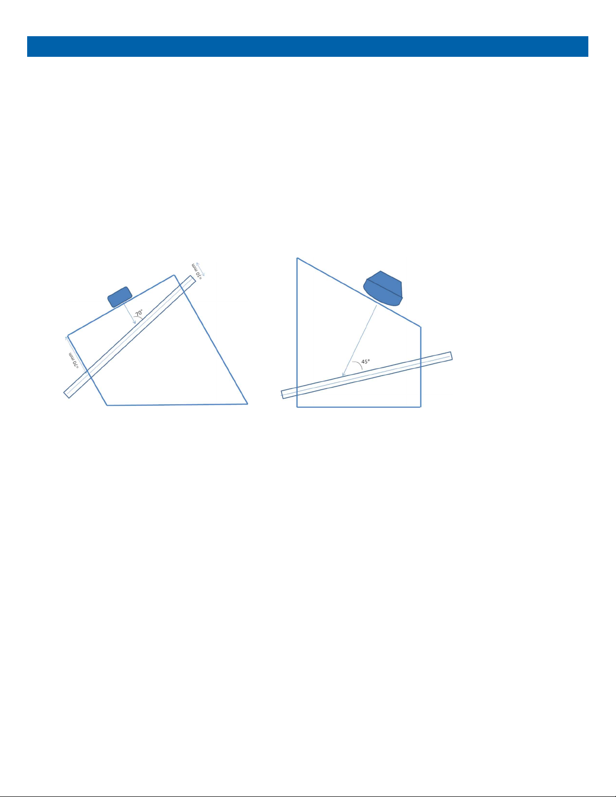
illustrates the two imaging configurations for the phantom.
Figure 1 Phantom used for peripheral Doppler imaging (left) and for abdominal applications (right).
The simulated vessel is embedded in tissue equivalent Zerdine® gel with the following acoustic properties:
Speed of sound: 1540 m/s
Attenuation coefficient: 0.7 dB/cm/MHz
Relative backscatter: 0 dB with respect to CIRS liver parenchyma reference
HANDLING PRECAUTIONS AND END OF LIFE DISPOSAL
With proper care, the tissue mimicking phantom enclosed with the Doppler Flow Simulator will withstand
years of normal use. Below are some guidelines to follow:
The scanning surface is the most important item on the phantom to protect. It can withstand normal scanning
pressure but DO NOT press on the scanning surface with your fingernails or any other sharp objects. If the
scanning surface becomes damaged, seal the phantom in an airtight container and IMMEDIATELY contact
CIRS for return authorization. Call 800-617-1177, email at rma@cirsinc.com or fax RMA Request form to 757-
857-0523.
The phantom may be cleaned with mild soap and water ONLY. Avoid solvent-based, alcohol-based, or
abrasive cleaning agents.

For longest life, the phantom should be stored at room temperature. The phantom SHOULD NOT be
subjected to freezing or boiling conditions such as those encountered in the trunk of a car during a South
Dakota winter or Arizona summer. The most accurate measurements will be made with the phantom 22˚C ±
1˚C (70˚F – 73˚F).
Always store the phantom with the removable storage cover attached and in the airtight carry case provided
to maximize life expectancy.
Zerdine® will desiccate over time if the phantom is not stored properly. If there is a noticeable change in the
phantom the phantom should be returned IMMEDIATELY for repair or replacement.
Inspect your phantom regularly for signs of damage.
Regular inspection for weight loss is essential to maintaining your phantom. At least once a
year, weigh your phantom and com- pare to original weight noted on certificate of compliance.
If phantom has lost or gained more than 1% of its original weight and you notice a difference in
vertical distance measurements, or the scan surface appears depressed, call CIRS at (800)
617-1177.
This product contains Zerdine, a non-flowing water-based, polyacrylamide material which is
fully sealed within the phantom housing. Zerdine contains trace amounts of residual monomer
acrylamide CAS#79-06-1. There are no known hazards when the phantom is used and stored
as intended. Zerdine is fully cured and will not leak from the housing. Damage to the integrity of
the housing may expose the user to Zerdine containing trace monomer acrylamide below levels
necessary to cause adverse health effects. Nonetheless, it is advised to wear protective gloves
if handling exposed Zerdine gel. It is also advisable to wash hands and all surfaces with soap
and water after handling exposed Zerdine gel.
Regulations regarding disposal of materials with trace acrylamide monomer vary by locality.
Contact your local authority for instructions. If assistance is desired in the proper disposal of
this product, including accessories and components, after its useful life, please return to CIRS.

Handling and Care
The phantom may be stored with the rest of the flow circuit connected, so long as the pump is used often. If
you do not anticipate further testing for several weeks, we recommend purging the circuit of blood mimicking
fluid to prevent particle agglomeration. To do so, follow the steps below:
1
.
Disconnect the reservoir outlet from the pump and leave the tube in the air.
2
.
Run the pump pumping until all remaining fluid is returned to the reservoir.
3
.
Turn off the pump, disconnect the reservoir cap and place it over a container of water. Turn the pump back
on and clean any remaining blood mimicking fluid from the circuit. When complete, turn off the pump. DO NOT
DRAIN THE REMAINING WATER FROM THE TUBES IN THE PHANTOM
.
This will prevent the tubing from
collapsing and extend the phantom lifetime.
4. Store the Doppler Flow Pump in accordance with the Model 769 User Manual.

TESTING PROCEDURES
Below is a description of the three most common Doppler ultrasound performance tests that may be
conducted with this phantom: sensitivity, velocity accuracy and angle error. Additional Doppler performance
tests of interest are described in detail in the following references.
1
.
Performance Criteria and Measurements for Doppler Ultrasound Devices: Technical Discussion; Second
Edition. AIUM Technical Standards Committee, 2002.
2
.
Testing of Doppler Ultrasound Equipment. Institute of Physical Sciences in Medicine, Report No. 79, ed.
PR Hoskins, SB Sherriff and JA Evans, 1994.
3
.
IEC TS 61895: Ultrasonics – Pulsed Doppler diagnostic systems – Test procedures to determine
performance. First edition, 1999-10.
For sensitivity, velocity accuracy and angle error tests described below, there will be considerable variability
based on the system settings and operator technique. In addition, there may be some measurement bias
between the pump settings and the velocity measurement. There- fore, it is recommended that when using
this phantom as part of a QA program, the user should conduct a series of baseline measurements to
establish the measurement error bars. These error bars are essential for establishing realistic pass/fail criteria
for annual QA checks of system performance, or when comparing the performance of different Doppler
ultrasound systems. For best results, we recommend archiving image data for future comparison, as the
image data contains more information about the measurement than a single-valued output.
SENSITIVITY (DEPTH OF PENETRATION)
1
.
Set the flow circuit for constant velocity flow.
2
.
Set pump flow rate to a clinically relevant flow condition. For instance, the internal carotid artery will
typically produce a peak systolic velocity of 100-120 cm/s. This is equivalent to a pump setting of 9-11 ml/s
(540 – 660 ml/min).

This pair of images shows cross section of tube 1 in color flow mode while be imaged at 10 MHz with
a linear array probe
.
The first image shows a clear color flow image at a depth of 2 cm
.
When moving
the transducer down the length of the tube, the color flow image disappears at a depth of 4 .5 cm
.
3
.
Increase scanner power output to 100% (maximum output)
4
.
For multi-frequency probes, use a mid-frequency Doppler transmit frequency set- ting. If no mid-frequency
setting is available, deviate to the most used frequency.
5
.
Place the ultrasound transducer over the deepest tube that is detectable with your transducer. A cross-sectional view
of the vessel is recommended for the most consistent results. Move the transducer down the length of the scanning
surface so that the vessel depth increases. Check for flow periodically until flow can no longer be detected (in pulse wave
Doppler, adjust gate position over vessel before each test). Note that during the first test, the Doppler gain and/ or
flow rate may need to be lowered until there is a loss of detectability.
6
.
Record the flow rate, Doppler settings and vessel depth when the flow signal was no longer detectable.
Subsequent tests should be conducted at the same flow rate and Doppler settings to determine if there is a
change in Doppler system sensitivity. Due to the subjectivity of this measurement, it is recommended that
users save images from each test to assist in comparing image quality over time.

VELOCITY ACCURACY
1
.
Set flow pump so that the average flow velocity is 20 cm/s. See “Pump Calibration” (page 11) for
instructions on converting volume flow rate to average flow velocity.
2
.
To ensure laminar flow, the scan region should be placed outside the minimum entrance length (>6 cm at
maximum flow velocity).
3
.
Enable Pulse-Wave mode. Image the tube in cross-section, set angle correction to that vessel angle and
set the pulse wave window to encompass the entire lumen. Estimate the maximum velocity (center of the
tube). For laminar flow, the maximum velocity will be double the average flow velocity.
4
.
Enable Color Flow mode. Scan flow tube in the cross-sectional position. Set the pulse repetition frequency
(PRF) to avoid aliasing and decrease until aliasing sets in. The maximum velocity corresponding to the PRF
setting is the maximum velocity in the flow tube.
Note: Color Flow only yields an average velocity, which should match the calibrated average flow velocity of
the flow pump.
ANGLE ERROR TEST
1. Set the flow circuit for constant velocity flow.
2
.
Enable Color Flow mode. Scan the flow tube in the longitudinal sectional position.
3
.
For orientation 1, which tests for abdominal applications, the angle between the membrane and the vessel
is 45°. Thus, the Doppler angle is 45° if the probe is placed normal to the membrane. The transducer should
be placed closer to the shallow end to measure the angle at the middle region of the tubing.
4
.
For orientation 2, which tests for peripheral applications, the angle between the membrane and the vessel is
20°. The Doppler angle is 70° if the probe is placed normal to the membrane.
5
.
Position the Doppler window on the center of the tube and correct the angle to that of the vessel. Record the
observed angle and freeze the image.
6
.
Measure the angle between the membrane and beam direction by using the caliper application. The corrected
Doppler angle is given by the equation given below:
Dopplercorrected =Dopplerrelative -(90°-probe)
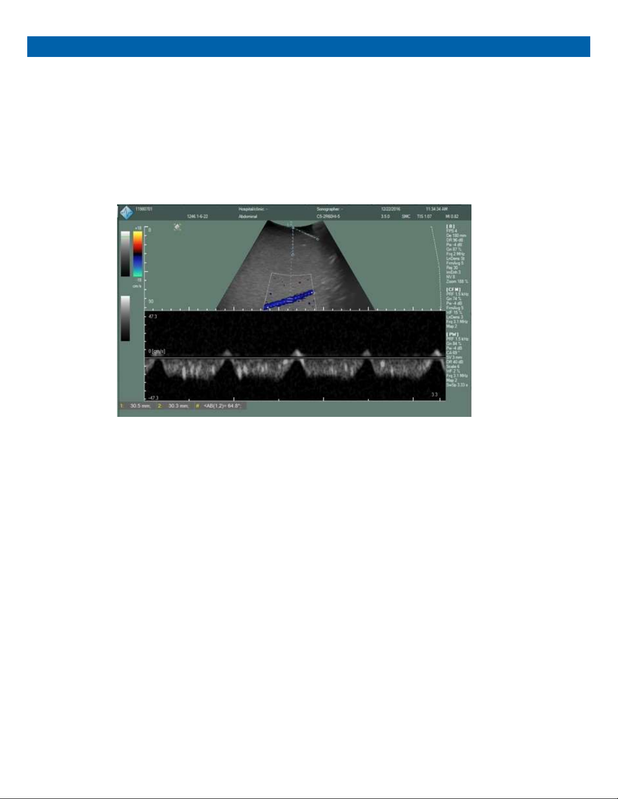
For linear transducers, the measurement will usually not be required since the probe angle will be
perpendicular. For curved transducers, it will be necessary to measure the probe angle for each
measurement. An example of a Doppler angle measurement with a curved transducer is shown in the image
below.
7
.
Compare the observed angle with the given angle.
Doppler angle error test with curved transducer. Calculations are provided below:
Dopplerrelative = 69°probe =64.8° Dopplercorrected =69°-(90°-64.8°) =43.8°

ZERDINE®
The Model 040GSE is constructed from a patented, solid elastic material developed at CIRS called Zerdine.
Phantoms constructed from Zerdine will not melt or leak when punctured and they do not require refrigeration.
Zerdine is also more elastic than other materials and allows more pressure to be applied to the scanning surface
without subsequent damage to the material. At normal room temperatures, Zerdine will accurately simulate the
ultrasound characteristics found in human liver tissue. Specific proprietary fabrication procedures enable close
control over the homogeneity of Zerdine and the reliability of its acoustic characteristics from batch to batch.
The formulation system established at CIRS is geared to independently control: • The speed of sound in the optimal
range of 1510 to 1700 m/s.
• Attenuation in the optimal range of 0.05 and 1.5 dB/cm-MHz.
• Scatter or relative contrast in the optimal range of -15 to +15 dB in relation to a scatter baseline equivalent to
human liver tissue.
• Elasticity with a Young Modulus in the optimal range of 4 to 90 kPa.
At normal room temperature, Zerdine response to ultrasonic excitations will simulate the ultrasonic response of
human tissue. The relation between the acoustic attenuation, A, and the acoustic frequency, F, is of the form A =
AoFn with values of the power coefficient, n, in the range of 0.8 to 1.10, indicating the proportional increase of the
acoustic attenuation with frequency. Backscatter characteristics can be adjusted through the addition of
predetermined amounts of calibrated scatter material and are fully compatible with harmonic imaging. Zerdine can
be molded into very intricate shapes, and the material can be cured in layers allowing the production of “multi-
tissue” phantoms. Zerdine, like most other phantom materials, will desiccate if unprotected; thus, all phantoms
must be stored properly. If stored in the case provided, your phantom should last many years.

WARRANTY
All standard CIRS products and accessories are warranted by CIRS against defects in material and
workmanship for a period as specified below. During the warranty period, the manufacturer will repair or, at its
option, replace, at no charge, a product containing such defect provided it is returned, transportation prepaid,
to the manufacturer. Products repaired in warranty will be returned transportation prepaid.
PRODUCT WARRANTY PERIOD
Electrical Products & Dynamic Phantoms 12 Months
There are no warranties, expressed or implied, including without limitation any implied warranty of
merchantability or fitness, which extend beyond the description on the face hereof. This expressed warranty
excludes coverage of, and does not provide relief for, incidental or consequential damages of any kind or
nature, including but not limited to loss of use, loss of sales or inconvenience. The exclusive remedy of the
purchaser is limited to repair, recalibration, or replacement of the product at manufacturer’s option.
This warranty does not apply if the product, as determined by the manufacturer, is defective because of
normal wear, accident, mis- use, or modification.
NON-WARRANTY SERVICE
If repairs or replacement not covered by this warranty are required, a repair estimate will be submitted for
approval before proceeding with said repair or replacement.
RETURNS
If you are not satisfied with your purchase for any reason, please contact Customer Service or your local
distributor prior to returning the product. Visit https://www.cirsinc.com/distributors/ to find your local distributor.
Call 800-617-1177, email rma@cirsinc.com, or fax an RMA request form to 757-857-0523. CIRS staff will
attempt to remedy the issue via phone or email as soon as possible. If unable to correct the problem, a return
material authorization (RMA) number will be issued. Non-standard or “customized” products may not be
returned for refund or exchange unless such product is deemed by CIRS not to comply with documented
order specifications. You must return the product to CIRS within 30 calendar days of the issuance of the RMA.
All returns should be packed in the original cases and or packaging and must include any accessories,
manuals and documentation that shipped with the product. The RMA number must be clearly indicated on the
outside of each returned pack- age. CIRS recommends that you use a carrier that offers shipment tracking for
all returns and insure the full value of your package so that you are completely protected if the shipment is
lost or damaged in transit. If you choose not to use a carrier that offers tracking or insure the product, you will
be responsible for any loss or damage to the product during shipping. CIRS will not be responsible for lost or
damaged return shipments. Return freight and insurance is to be pre-paid.
With RMA number, items may be returned to:
CIRS
Receiving
900 Asbury Ave,
Norfolk, Virginia, 23513 USA

APPENDIX 1: CONVERSION OF FLOW
RATE TO FLOW VELOCITY
When used with the supplied phantom, which has 3/16” ID tubing, the pump flow rate may be converted to
flow velocity using the conversion chart supplied in the table below. The conversion from flow rate to average
flow velocity is made by dividing the flow rate by the cross-sectional area of the tubing, which is 0.18 cm2 for
3/16” tubing. For laminar flow, the flow velocity at the center of the tube is double the average flow velocity.
Thus, in constant velocity mode, the maximum flow velocity is double the average flow velocity. In pulsatile
mode, the maximum flow velocity depends on the shape of the pulse profile. Assuming a simple sine wave,
the peak flow velocity will be double the maximum flow velocity in constant velocity mode.
CONVERSION CHART FOR FLOW VELOCITIES
Flow Rate
(ml/s)
Flow Rate
(ml/min)
Average Flow
Velocity (cm/s)
Maximum Flow Velocity:
Constant Velocity Mode
(cm/s)1
Peak Flow Velocity:
Pulsatile Mode (cm/s)2
1 60 5.6 11.2 22.5
2 120 11.2 22.5 44.9
3 180 16.8 33.7 67.4
4 240 22.5 44.9 89.8
5 300 28.1 56.1 112.3
6 360 33.7 67.4 134.7
7 420 39.3 78.6 157.2
8 480 44.9 89.8 179.6
9 540 50.5 101.0 202.1
10 600 56.1 112.3 224.5
11 660 61.7 123.5 247.0
12 720 67.4 134.7 269.5
1Assume laminar flow
2Assumes simple sine wave pulse


Table of contents
Other Cirs Test Equipment manuals


