Jomox T-RACKONIZER User manual

T-RACKONIZER
EURO RACK FILTER MATRIX MODULE
Operating Manual

Thank you for using the Jomox T-Rackonizer! We hope that you will enjoy
this unique de ice and ha e lots of fun with it.
The T-Rackonizer is the eurorack successor of our ery sucessful T-
Resonator which did ery well o er the past years. It has been the least
possible implementation of the former experimental filter network
synthesizer called „Resonator Neuronium“. The number of 6 nodes had
been reduced to only two filter nodes – but still this structure offers a
tremendous ariety of sounds.
The module contains 2 analog T-ladder moog-like filters and a digital delay.
“T“ stands for “Time“.
“The T-Rackonizer transforms timely events into an analog filter feedback
network.“
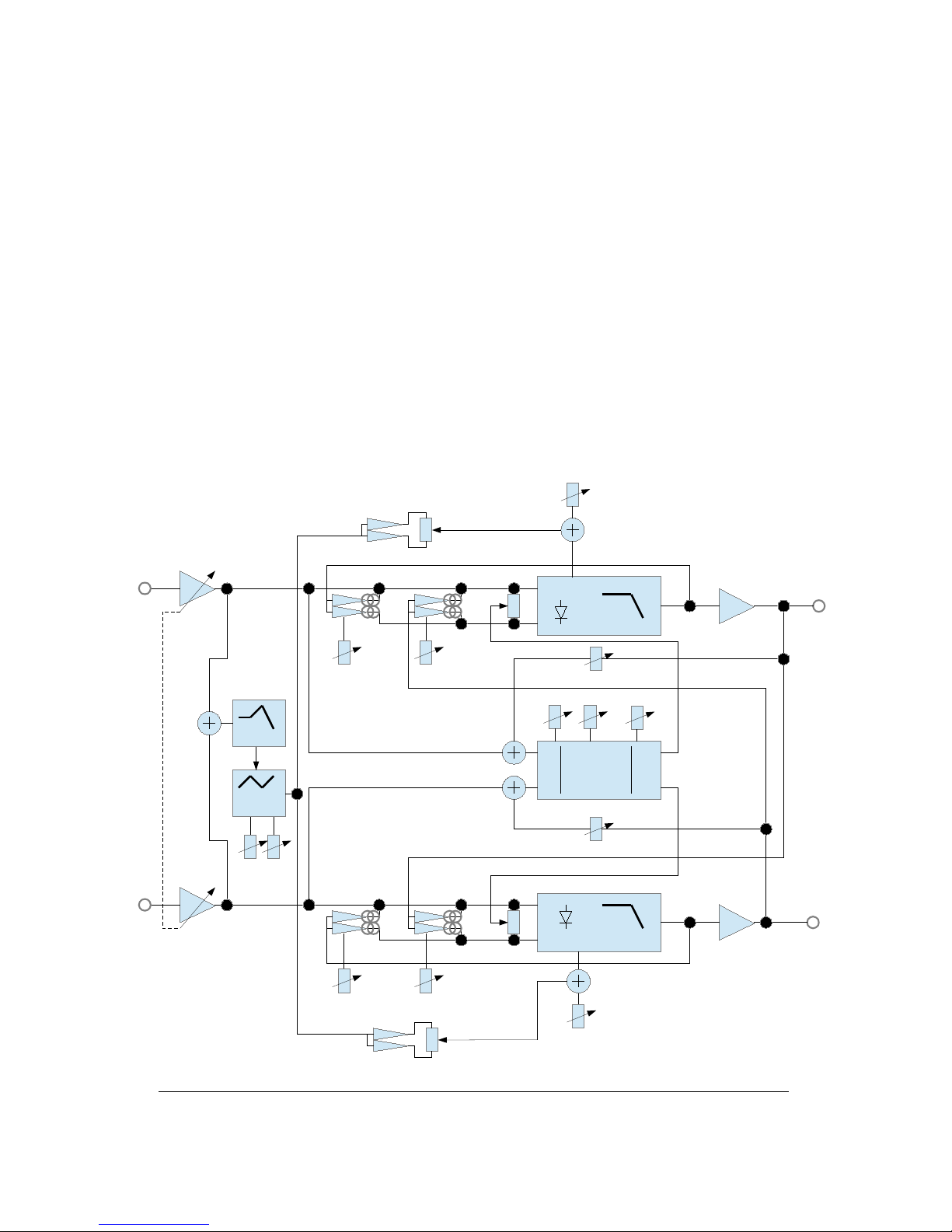
● What does that mean? The T-Rackonizer is a stereo filter made with
analog circuits and capable of feedback, with an integrated stereo digital
delay. The digital delay, which features analog feedback loops, is literally
“wo en” into the circuits.
● The stereo filter contains e ery possible internal feedback path, all
controlled using the Feedback and Mix 1 2 controls, with a dedicated knob
for each of them.
● The filters are two 4-pole, 24 dB/octa e transistor ladders made entirely
from discrete parts.
● On the T-Rackonizer, the mix, feedback and cutoff controls can be CV-
controlled (CV = control oltage). Once you insert a CV cable into the CV
jacks, the corresponding internal control knob (e. g. Cutoff) acts as an
amount to the external CV. Without CV input, the control knobs work o er
the full internal range.
On the mid-zeroed controls a oltage of 2.5 V represents the center
position. This only yields if the amount (= the corresponding control knob)
is fully turned clockwise.
● 8 different chorus/delay/re erb algorithms can be chosen for the delay
section, which includes 2 independent delay lines with different delay times
and feedbacks. The delay times extend from less than 1ms to 1 second,
the actual range and structure depending on the chosen algorithm.
● Also the program select can be CV-controlled. The control oltage is
added to the internal selection. If the range exceeds number 8, it rolls o er
to program 1.
2 T-Rackonizer Operating Manual

● Moreo er, the T-Rackonizer contains a sine wa e LFO that can run on its
own or be shaped by the audio en elope. All aspects of the LFO are
controlled by a single knob. In the center position the amount is zero,
turning to the left controls audio-en eloped LFO, and turning to the right
controls LFO running freely.
● The sine LFO gets retriggered by the audio signal depending on the input
gain. The en elope is generated by an audio en elope follower, and the
LFO and en elope can be combined.
● Extremely ersatile modulations are possible with this unique structure.
● The delay feedback routes back from the outputs of the analog filters into
the analog inputs of the delay line.
● You can easily create seesaw analog echoes, “Klingon”alien insect oices
using extreme feedback or membrane-like sounds by “wa e guide”
algorithm and many more.
● Because the feedback audio is analog, the resulting audio sounds ery
organic. The screaming analog feedback can repeat itself ia delay and
create new sound patterns by layering.
Caution: On some settings of filter feedback, extremely loud and powerful
bass signals or feedback sounds may occur that can damage your speakers
or ears! If you are not familiar with the device, please consider using a
limiting device or a lower mixing level!!
3 T-Rackonizer Operating Manual

Installation
Please turn off the euro rack prior to the installation! On the backside of
the T-Rackonizer module you can find these connections:
4 T-Rackonizer Operating Manual

Installation in the eurorack
Please connect the supplied ribbon cable to the eurorack system bus rails
as shown on the pictures. The module needs +/-12 Volts at a supply
current of maximum 130mA on +12V and about 70mA on -12 Volts. The
optional 5 Volts and the CV/Gate on the A-100 Doepfer bus are both not
wired inside the Jomox module and not needed.
Other 10 pin systems may be used as well if only the lower part of the 16
pin connector is connected.
Please pay attention for the position of the oltages and the ground pins!
The printed voltages must match, please check the wires again and
make sure no pin is left or bent.
There are protection diodes inside the modules but please take extra care
to protect the rack and the module!
A-100 Doepfer bus. (The
Doepfer GmbH
enterprise and all of
their shown products are
registered trademarks.
With friendly appro al of
Doepfer Musikelektronik
GmbH)
Jomox T-Rackonizer euro rack supply connector. Please connect the power
supply of the eurorack system bus here.
5 T-Rackonizer Operating Manual

Attention: DO NOT connect, under any circumstances, the power
supply cable to the omox Inter-D-module bus!!! The rack power
supply and the module could get seriously damadged!
Then please mount the module on the rack rails using the supplied metric
M3 screws.
6 T-Rackonizer Operating Manual

Audio inputs:
Please connect the audio signals to be processed here.
The T-Rackonizer has Hi-Z (high impedance) unbalanced inputs, allowing
you to plug in an instrument like an electric guitar or a bass directly
without any loss in sound. The gain reser e is enough to amplify a weak
guitar signal to dri e the filters. Unbalanced line audio signals of almost
any le el can also be processed.
Audio outputs:
The output signals of both filters are split out here.
7 T-Rackonizer Operating Manual
+
-
+
-
L
R
IN L
IN R
FX PROC
L
R
OUT R
OUT L
ENV
LFO
CUT
+
-
-
+
-
+
-
+
-
+
-
FEEDB MIX 2>1
FEEDB MIX 1>2
DELAY IN
DELAY IN
CUT
+
-
CUTOFF
ENV AMT
ENV AMT
CUTOFF
PROG 1-8P1 P2
DELAY FEEDB
DELAY FEEDB
CV
CV CV
CV
CV CV
CV
INT RATE
FILTER
FILTER
T-RACKONIZER BLOCK DIAGRAM
GAIN
GAIN
IN OUT

User Interface Analog Section
Gain:
This adjusts the sensi ity of the input. If the signal o erloads the input, all
8 LEDs of the program selection will light up. Howe er, the unit has
considerable headroom and is quite resisti e to o erloading. You can
(ab)use the distortion of filters creati ely without ha ing to fear that the T-
Rackonizer will be damaged.
LFO Intensity:
Controls the intensity of the LFO/en elope signal. At center position, the
intensity is zero. When you turn to the left, the resulting modulation signal
is a combination of audio en elope and LFO. The en elope masks the LFO.
So, the signal is dependent on the input signal and the LFO.
E n v + LF O
E n v e o pe
Turning to the right controls the LFO running freely on its own, fully
independent of the audio signal.
L F O
The sine LFO wa e is re-triggered by peaks in the audio signal. The
threshold itself is fixed, but it can be aried by the adjustment of the Gain
control.
LF O
A U D I O
R e st ar t
8 T-Rackonizer Operating Manual

LFO Rate:
This parameter controls the LFO frequency (period) and ranges from
approximately 0.15Hz (7sec) to about 22Hz (45ms).
If the LFO Rate is set ery low and the LFO Intensity is turned to the left,
the en elope alone determines the resulting modulation signal, so it is
possible to seamlessly adjust between a pure en elope signal and an LFO-
modulated en elope signal.
L F O R a te s m a E n v e o pe
L F O R a te = 0
E n v e o pe
Env Amt 1:
This knob determines how the en elope signal modulates the cutoff
frequency of the left filter (En elope Amount). In the center position, the
cutoff of the filter is not changed. As you turn it to the right, the filter
cutoff opens further, and the corresponding right LED lights up. If you turn
it to the left, the filter gets closed in the rhythm of the en elope signal, and
the left LED lights up.
The LEDs show the phase of the modulating signal. If LFO intensity and
Env Amount are set to high le els, both LEDs may light up alternating on
sine LFO. They light up in the rhythm of the phase of the modulation
signal.
Env Amt 2:
This operates exactly like En Amt 1, but affects only the cutoff frequency
of the right filter.
Mix 2-1:
With this knob, you can mix the output signal of the right filter with
positi e or negati e phase into the left filter. At center position the
intensity is zero. Turning to the left increases the negati e phase
9 T-Rackonizer Operating Manual

feedback, and turning to the right increases the positi e phase feedback.
Depending on the other parameters, e en small de iations from the
midpoint may lead to rather extreme changes of sound.
Mix 1-2:
This operates exactly like Mix 2-1, but with this knob, you can mix the
output signal of the left filter with positi e or negati e phase into the right
filter.
The two Mix knobs can bring some interesting results. When Mix 1-2 and
Mix 2-1 are turned in opposite directions, the outputs will be out of phase
with each other, resulting in ery narrow band screaming filters! On the
other hand, setting the two knobs similarly will create strong bass
enhancements ia phase doubling.
Experiment and ha e fun!
Cutoff:
These knobs change the corner frequency of both low pass filters. The
more either knob is turned to the left, the duller its signal will become (as
the high frequencies get filtered). The more either knob is turned to the
right, the more its filter will open up, and its signal will become brighter.
Howe er, other parameters may also affect the cutoff, for example
en elope amount. With the cutoff controls, you are just setting the basic
alue on which the other modulations add or subtract.
Feedback:
At center position there is no feedback. Turning to the right resembles the
typical resonance of a normal music filter. If you turn it to the left though,
the filter reaches a fairly unstable state by positi e feedback. Vibrations
appear that are similar to LFOs, and in extreme positions ery low bass
tones can result.
Caution: On some settings of filter feedback, extremely loud and powerful
bass signals or feedback sounds may occur that can damage your speakers
or ears! If you are not familiar with the device, please consider using a
limiting device or a lower mixing level!!
10 T-Rackonizer Operating Manual

User Interface Digital Delay Section
The built-in digital stereo delay takes a part of the input audio signal and
passes it through its arious delay, chorus or re erb algorithms.
The output signal from the delay can be fed into the filter with positi e or
negati e phase ia the knobs Delay In (1+2).
Then, the knobs Delay Feedback (1+2) feed the analog signal from the
filter back into the analog input of the delay.
Program:
This knob chooses the delay program. One of 8 LEDs arranged in a circle
light up for the currently selected program. Both parameters Para 1 and
Para 2 ha e different functions and ranges for different programs. Also,
the LFO may modulate single parameters in arious programs.
Please find more information about the different programs in the following
table:
No. Program Description Para 1 Para 2 LFO/Envelope
1 Tracker Audio VCO Tracker VCO
Volume
PLL
Tracking
Chorus
Intensity
2 Siner Sine Wa e en eloped
+ modulated by Audio
Sine
Frequency
Input->FM
Modulation
Sine Amount
En elope
3 Warp Audio VCO Tracker +
Pipes mixed to obtain
crazy effect
Pipe 1
length
Pipe 2
length
Pipe 3+4 length
4 Wa eguide 4 short wa e pipes
(delay lines)
delay range 0.6-30ms
Pipe 1
0.6-30ms
Pipe 2
0.3-15ms
Pipe 3+4 length
5 Delay I 2 equally long delays
3ms-0.5s
Delay 1 Delay 2
6 Delay II One long delay +
one short delay
Delay 1
3ms-1s
Delay 2
0.6-60ms
7 Re erb I Re erb program 1 HP Filter Re erb
Time
LP Filter
8 Re erb II Re erb program 2 HP Filter Re erb
Time
LP Filter
11 T-Rackonizer Operating Manual

Para 1 / Para 2:
These knobs adjust the alues for the defined parameters in the delay
programs. Please note that in some programs the LFO Intensity also has
an effect on the delay program.
Delay In (1+2):
With these knobs, you can mix the output signal of each delay into its
corresponding filter with either positi e or negati e phase. In center
position the intensity is zero.
As described in section Mix 1-2, you can obtain interesting effects using
either phase cancellation or phase doubling of the two delay lines.
Delay Feedback (1+2):
These knobs control the feedback from each filter output to the input of the
corresponding digital delay. Turned fully counterclockwise, the amount is
zero.
12 T-Rackonizer Operating Manual

CV Controlled Parameters
Opposing to the T-Resonator, the T-Rackonizer uses a CV (control oltage)
for the most important control knobs. The signal is not being attenuated by
a potentiometer but by a VCA ( oltage controlled amplifier) and uses a CV
for operation. Therefore, the internal control knobs only apply a CV to the
circuitries.
If you insert a plug into the corresponding jack, the external CV is
attenuated by the control knob, which makes them act as an amount to the
external CV. See diagram:
Feedback CV:
Please keep in mind that the internal Feedback knob is an amount to the
external CV once you ha e plugged in a CV cable.
As Feedback is a dual polarity control, the internal CV needs to reach 2.5
Volts for Feedback center position (=zero). This can be achie ed if you turn
up the internal control knob fully clockwise. With a CV range of 0..5 V you
can now go through e ery position of the Feedback parameter.
Howe er, if you only turn up the knob halfway to center position, you
would need to apply 5V to reach the center position and 10V to go across
into the positi e area. As most CV sequencers only deli er 0 to 5 Volts you
need to open the Feedback knob fully clockwise to ha e the full control
range.
13 T-Rackonizer Operating Manual
CV 0-5V
UNPLUGGED: CUTOFF
PLUGGED: CV AMOUNT
CV INPUT DIAGRAM
5V
CV JACK
POTENTIOMETER
TO CIRCUIT

Cutoff CV:
Please keep in mind that the internal Cutoff knob is an amount to the
external CV once you ha e plugged in a CV cable.
If you turn up the Cutoff control knob fully clockwise, the CV range goes
from 0..5 V. Howe er, if you only turn up the Cutoff knob halfway, you
would need a CV range of 0 to 10V to ha e the full range. Most CV
sequencer's CV ranges are limited to 5 Volts though.
Mix CV:
Please keep in mind that the internal Feedback knob is an amount to the
external CV once you ha e plugged in a CV cable.
As Mix is a dual polarity control, the internal CV needs to reach 2.5 Volts
for Mix center position (=zero). This can be achie ed if you turn up the
internal control knob fully clockwise. With a CV range of 0..5 V you can
now go through e ery position of the Mix parameter – which is important
as the mix parameter can cause se ere feedback and screaming sounds if
not smoothly adjusted.
Howe er, if you only turn up the knob halfway to center position, you
would need to apply 5V to reach the center position and 10V to go across
into the positi e area. As most CV sequencers only deli er 0 to 5 Volts you
need to open the Mix knob fully clockwise to ha e the full control range.
14 T-Rackonizer Operating Manual

Quick Start Guide
Turn both Env Amounts, Mix 2-1, Mix 1-2 and the Feedback knobs to the
center position. Turn Delay In on both sides to center position and select
Program 6 (Delay II), set LFO Intensity to 3 o’clock position, LFO Rate to
about 11 o’clock and Gain to center position.
If you apply a line le el signal to the inputs and tweak the cutoff knobs, the
M-Resonator will act like a normal stereo low pass filter.
Now let’s look at the feedback knobs. A turn to the right produces the
expected filter resonance whistling, but in the opposite direction, the knob
creates a totally different reaction. At low amounts you can hear an
increase in bass until the filter starts to create extremely deep ibrations
like a bass tone.
Welcome, Godzilla!
Re-center them again to get a neutral position.
Turn both filter cutoffs to the center position. As soon as you turn the Env
Amt (en elope amounts) to the left, the filters start to open and close in
the rhythm of the LFO. You can watch the LFO on the LEDs. If you turn Env
Amt to the right, the phase of the LEDs (and that of the filter cutoff)
changes. Watch and hear the filters close and open to the rhythm of the
LEDs.
Now turn Delay In 1 (affecting the left hand filter) a little bit to the left.
You can hear the echoed input signal. With Delay Feedback you can control
the number of echoes and with Para 1, the delay time.
You can do the same for the right side, but it will sound different, because
in this particular program there is only a ery short delay on this side. So,
just crank up Delay In and Delay Feedback on the right filter. Now apply a
little Mix 1-2 and Mix 2-1 in counter directions, and the little module will
already start to produce some pretty weird sounds ;)
Most of the other knobs cause ery complex interactions between both
filters and therefore it is not possible to describe these actions in an easy
way. They are ery much dependent on the audio material and knob
settings relati e to each other. Sometimes only a ery little change of one
knob causes the whole sound to change into something totally different.
At this point we would like to encourage you to tweak and twiddle and
experiment with this unique filter box. Note that the structure of the stereo
filter is symmetrical. So it is ery interesting to create ”mirrored” knob
settings that feed back signals in both ways and turn the 2 filters into a
multi-resonant complex feedback machine.
15 T-Rackonizer Operating Manual

Welcome to the wonderful world of the JoMoX T-Rackonizer!
Don't get discouraged too soon – we belie e that we ha e created a little
instrument of its own that wants to be learned and rehearsed. It rewards
you with a bunch of really organic sounding weird sci-fi sounds that would
require a lot more of modules and efforts if patched from single modules.
And finally...
Ser ice, tips and tricks:
JoMoX GmbH
Körtestr. 10
10967 Berlin / Germany
http://www.jomox.com
E-Mail [email protected]
May you ha e lots of fun and success with creati e usage on all of our
products!
Berlin, January 2016
Jürgen Michaelis
16 T-Rackonizer Operating Manual

T-RACKONIZER
EURO RACK FILTER MATRIX MODUL
Bedienungsanleitung

Wir freuen uns, dass Sie sich für einen T-Rackonizer on Jomox
entschieden haben und wünschen Ihnen iel Freude mit dem Gerät!
Der T-Rackonizer ist die Euro-Rack Version unseres äußerst erfolgreichen
T-Resonators, der sich in den letzten Jahren sehr gut erkauft hat. Er war
ursprünglich die kleinste mögliche Implementierung des experimentellen
Filternetzwerk-Synthesizers namens „Resonator Neuronium“. Die Zahl on
sechs Knoten wurde auf zwei Filterknoten begrenzt, und trotzdem bietet
diese relati einfache Struktur eine unglaubliche Vielzahl on Sounds.
Das Modul enthält 2 analoge Moog-ähnliche Filter und einen digitalen
Effektchip.
„T“ steht für „Time“.
„Der T-Rackonizer transformiert zeitliche Vorgänge in ein analoges
rückgekoppeltes Filternetzwerk.“
● Was bedeutet das? Der T-Rackonizer ist ein aus analoger
Schaltungstechnik aufgebautes rückkoppelbares Stereo-Filter mit einem
integriertem Stereo Digital Delay. Das Delay ist mit ebenfalls analogen
Rückkoppelungsschleifen in die Schaltung „eingewebt“.
● Das Stereo-Filter hat alle erdenklichen Rückkoppelungswege wie
Feedback und Mix1/2, die alle über eigene Potis eingestellt werden können.
● Die Filter sind zwei 24-pol Transistorkaskaden Tiefpassfilter, die
ollständig aus diskreten Bauteilen aufgebaut sind.
● Beim T-Rackonizer sind die Feedback-, Mix- und Cutoff-Regler als CVs
(CV = Control Voltage = Steuerspannung) ausgeführt. Sowie man einen
Stecker in die betreffende CV-Buchse steckt, arbeitet der interne Regler als
Amount für die eingehende CV. Ohne CV-Stecker arbeiten die internen
Regler über den gesamten CV-Bereich (0-5 Volt).
Bei den mittensymmetrischen Parametern wie Feedback und Mix ist die
Mittelstellung Null. Dies entspricht intern einer CV on 2.5 Volt, die man
am besten erreichen kann, wenn der interne CV-Regler oll aufgedreht ist.
● Für die Delay-Sektion können 8 erschiedende Chorus/Delay/Re erb
Algorithmen ausgewählt werden, bei denen jeweils 2 unterschiedliche
Delay Lines mit unterschiedlichen Zeiten und Feedbacks eingestellt werden
können.
Delays reichen on unter 1 ms bis zu einer Sekunde, der Bereich und die
Struktur sind abhängig om ausgewählten Algorithmus.
● Auch die Programmauswahl kann über CV gesteuert werden. Die
Steuerspannung wird zu der internen Programmauswahl hinzu addiert.
Wenn der Regelbereich über das Programm 8 hinausgeht, springt die
Auswahl wieder auf Programm 1 über.
T-Rackonizer Bedienungsanleitung
18

● Ferner enthält der T-Rackonizer noch einen Sinus-LFO, der sowohl
freilaufend sein kann als auch mit der Audio-Hüllkur e überlagert werden
kann. Alles wird über einen einzigen Regler eingestellt. In der
Mittenposition ist das Amount 0, nach links ist es Hüllkur e mit LFO, nach
rechts LFO allein.
● Der Sinus-LFO wird durch das Audiosignal neu getriggert, abhängig om
eingestellten Input Gain. Die Hüllkur e wird durch einen En elope Follower
aus dem Audiosignal generiert. LFO und Hüllkur e können kombiniert
werden.
● Extrem umfangreiche Modulationsmöglichkeiten sind durch diese
einzigartige Struktur möglich.
● Das Delay-Feedback geht über die Ausgänge der analogen Filter zurück
in die Analogeingänge der Delay Line.
● Damit können sich aufschaukelnde Analog-Echos, „Klingonen-Parties“
durch extremes Feedback oder saitenähnliche Sounds durch den „Wa e
Guide“ Algorithmus und ieles mehr erzeugt werden.
● Durch die analoge Rückkoppelung klingt alles organisch.
Die kreischenden Analog-Feedbacks können sich selbst delayen und dabei
neue Soundpattern bilden.
Vorsicht! Bei bestimmten Einstellungen der Filter-Feedbacks kann es zu
extrem lauten Bass-Signalen oder Rückkoppelungen kommen, die unter
Umständen Ihre Lautsprecher oder Ihre Ohren schädigen könnten! Wenn
Sie unerfahren in der Bedienung des T-Rackonizers sind, dann verwenden
Sie bitte einen Limiter oder leisere Einstellungen!
T-Rackonizer Bedienungsanleitung
19

Installation
Schalten Sie or dem Einsetzen des Moduls das Eurorack aus! Auf der
Rückseite des T-Rackonizers finden Sie folgende Anschlüsse:
T-Rackonizer Bedienungsanleitung
20
Other manuals for T-RACKONIZER
1
Table of contents
Languages: