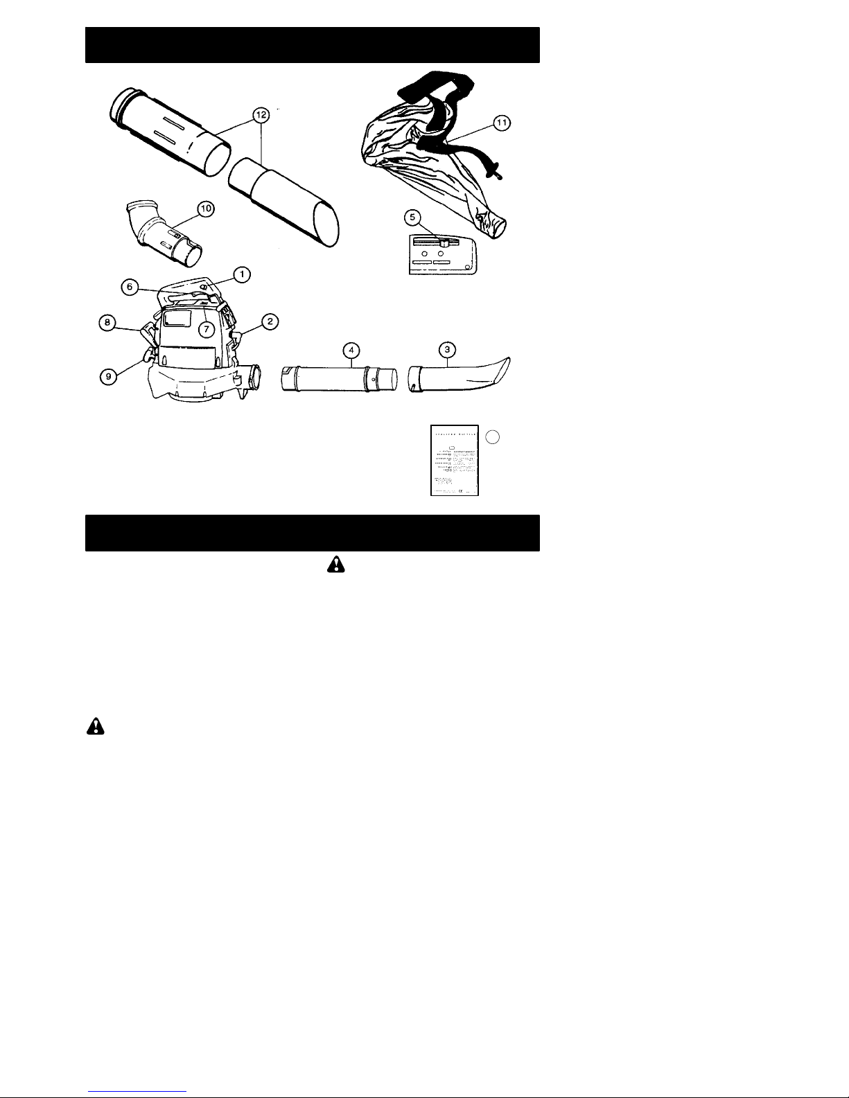
Jonsered BV32 User manual

Bedienungsanweisung
Manual de instrucciones
Libretto d’Istruzioni
Lesen Sie diese Hinweise zur Handhabung des
Geräts aufmerksam durch. Verwenden Sie es erst,
wenn Sie sicher sind, daß Sie alle Anweisungen
verstanden haben.
Lea atentamente las instrucciones y asegúrese de
entenderlas antes de utilizar este unidad.
Leggere attentamente queste istruzioni e accertarsi
di averle comprese prima di usare l’unità.
530088114 5/28/02
Deutsch
Italiano
Español
Instruction Manual
Manuel d’instructions
English
Français
Please read these instructions carefully and make
sure you understand them before using this unit.
Avant d’utiliser cet appareil, veuillez lire attentive-
ment les instructions et assurez--vous de les avoir
comprises.
ENGLISH FRANÇAIS DEUTSCH ITALIANO
ESPANOL
Lees deze instructies zorgvuldig en wees er zeker
van dat u ze begrijpt alvorens dit apparaat te gebrui-
ken.
Handleiding
Nederlands
NEDERLANDS
JONSERED SERVICE

-- 2 --
KEY TO SYMBOLS
WARNING! This blower
can be dangerous! Care-
less or improper use can
cause serious or even fa-
tal injury.
Read and understand the
instruction manual before
using the blower.
WARNING! Be sure the
bottom cover is secured
or the vacuum tube is
properly installed. Avoid
the impeller blade with
your hand or any foreign
object.
Instructions on how to
open vacuum inlet cover.
Use unleaded or quality
leaded petrol and two
stroke oil.
Always wear eye and ear
protection.
Checks and/or maintenance
should be carried out with
the engine switched off, with
the stop switch in the OFF
position.
SAFETY RULES
WARNING: Failure to follow all
Safety Rules and Precautions can result in
serious injury.
KNOW YOUR UNIT
SRead your instruction manual carefully until
you completely understand and can follow all
warnings and safety rules before operating
the unit.
DRestrict unit to users who understand and will
follow all warnings and safety rules in this
manual.
WARNING: Inspect area before start-
ing unit. Remove all debris and hard objects
such as rocks, glass, wire, etc. that can rico-
chet, be thrown, or otherwise cause injury or
damage during operation.
Use your unit as a blower for:
DSweeping debris or grass clippings from
driveways, sidewalks, patios, etc.
DBlowing grass clippings, straw, or leaves into
piles, around joints, or between bricks.
Use your unit as a vacuum for:
DPicking up dry material such as leaves, grass,
small twigs, and bits of paper.
DFor best results during vacuum use, operate
your unit at high speed.
DMove slowly back and forth over the material
as you vacuum. Avoid forcing the unit into a
pile of debris as this can clog the unit.
DKeep the vacuum tube about an inch above
the ground for best results.
PLAN AHEAD
DAlways wear eye protection when operating,
servicing, or performing maintenance on unit.
Wearing eye protection will help to prevent
rocks or debris from being blown or
ricocheting into eyes and face which can
result in blindness and/or serious injury. Eye
protection should be marked Z87.
DAlways wear foot protection. Do not go
barefoot or wear sandals.
DAlways wear respirator or face mask when
working with unit in dusty environments.
DSecure hair above shoulder length. Secure or
remove jewelry, loose clothing, or clothing
with loosely hanging straps, ties, tassels, etc.
They can be caught in moving parts.
DDo not operate unit when you are tired, ill,
upset, or if you are under the influence of
alcohol, drugs, or medication.
DKeep children, bystanders, and animals away
from work area a minimum of 10 meters when
starting or operating unit. Do not point blower
nozzle in the direction of people or pets.
The operator of the
machine must insure
that no one comes
within a 10 meter ra-
dius while working.
When several opera-
tors are working within
the same area, a safe-
ty distance of at least
10 meters must be ob-
served.

-- 3 --
WARNING!
The blower can throw
objects violently.
--You can be blinded
or injured.
--Always wear eye
protection.
Thrown
objects
HANDLE FUEL WITH CAUTION
DEliminate all sources of sparks or flame
(including smoking, open flames, or work that
can cause sparks) in the areas where fuel is
mixed, poured, or stored.
DMix and pour fuel in an outdoor area; store
fuel in a cool, dry, well ventilated place; use an
approved, marked container for all fuel
purposes.
DDo not smoke while handling fuel or while
operating the unit.
DMake sure the unit is properly assembled and
in good operating condition.
DDo not fill fuel tank while engine is hot or
running.
DAvoid spilling fuel or oil. Wipe up fuel spills
before starting engine.
DMove at least 3 meters away from fuel and
fueling site before starting engine.
DAlways store petrol in a container approved
for flammable liquids.
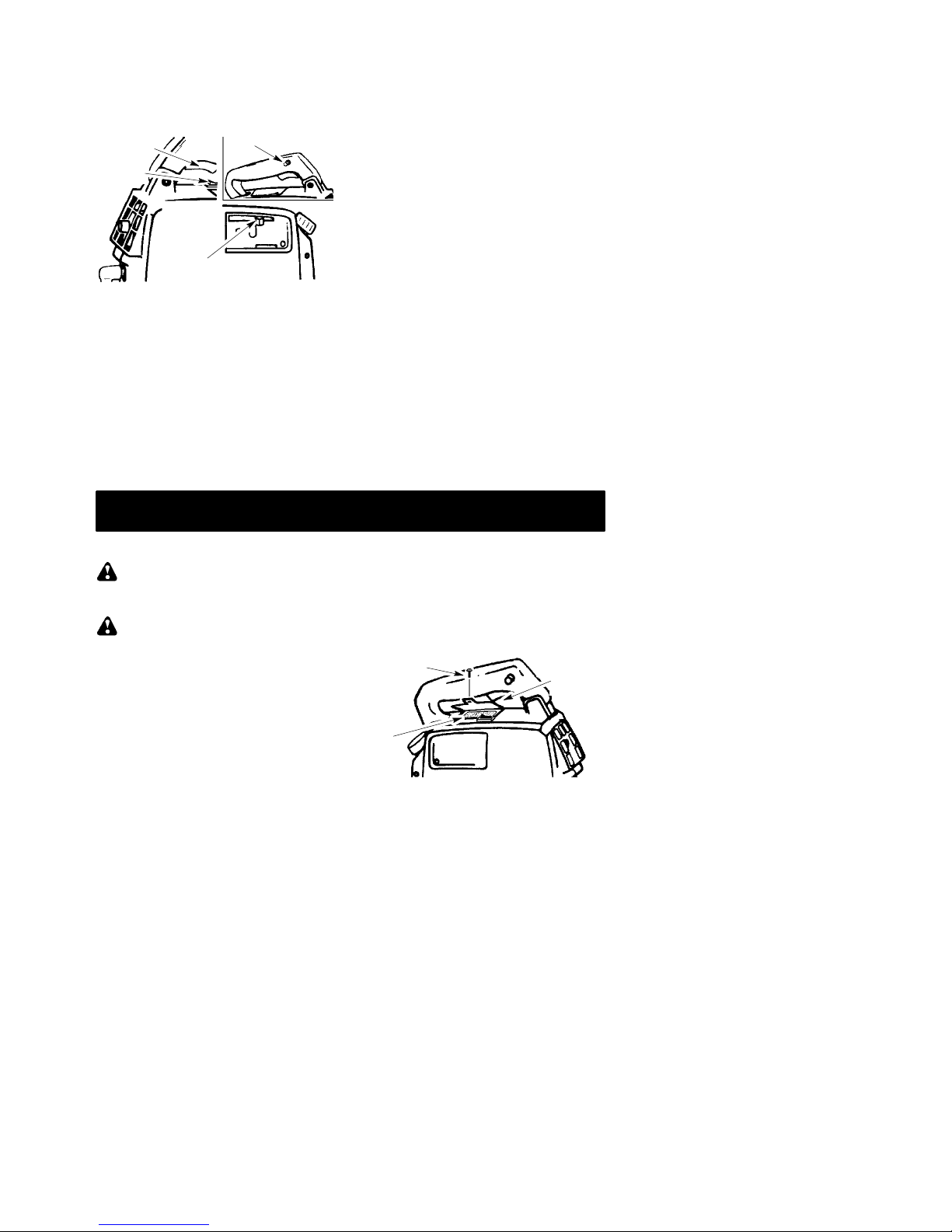
OPERATE YOUR UNIT SAFELY
WARNING: Stop the engine before
opening the vacuum inlet door. The engine
must be stopped and the impeller blades no
longer turning to avoid serious injury from the
rotating blades.
DInspect unit before each use for worn, loose,
missing, or damaged parts. Do not use until
unit is in proper working order.
DKeep outside surfaces free of oil and fuel.
DNever start or run engine inside a closed
room or building. Breathing exhaust fumes
can kill.
DTo avoid static electricity shock, do not wear
rubber gloves or any other insulated gloves
while operating unit.
DDo not set unit on any surface except a clean,
hard area while engine is running. Debris
such as gravel, sand, dust, grass, etc. could
be picked up by the air intake and thrown out
through discharge opening, damaging unit,
property, or causing serious injury to
bystanders or operator.
DAvoid dangerous environments. Do not use in
unventilated areas or where explosive vapors
or carbon monoxide build up could be
present.
DDo not overreach or use from unstable
surfaces such as ladders, trees, steep
slopes, rooftops, etc. Keep firm footing and
balance at all times.
DNever place objects inside the blower tubes;
always direct the blowing debris away from
people, animals, glass, and solid objects such
as trees, automobiles, walls, etc. The force of
air can cause rocks, dirt, or sticks to be
thrown or to ricochet which can hurt people or
animals, break glass, or cause other damage.
DNever run unit without the proper equipment
attached. When using your unit as a blower,
always install blower tubes. When using your
unit as a vacuum, always install vacuum
tubes and vacuum bag assembly. Make sure
vacuum bag assembly is completely zipped.
DCheck air intake opening, blower tubes,
vacuum tubes, and elbow tube frequently,
always with engine stopped and spark plug
disconnected. Keep vents and discharge
tubes free of debris which can accumulate
and restrict proper air flow.
DNever place any object in the air intake
opening as this could restrict proper air flow
and cause damage to the unit.
DNever use for spreading chemicals, fertilizers,
or other substances which may contain toxic
materials.
DTo avoid spreading fire, do not use near leaf or
brush fires, fireplaces, barbecue pits,
ashtrays, etc.
DUse only for jobs explained in this manual.
MAINTAIN YOUR UNIT PROPERLY
DHave all maintenance other than the
recommended procedures described in the
instruction manual performed by an
authorized service dealer.
DDisconnect spark plug before performing
maintenance except for carburetor
adjustments.
DUse only recommended Jonsered®
replacement parts; use of any other parts
may void your warranty and cause damage to
your unit.
DEmpty fuel tank before storing the unit. Use
up fuel left in carburetor by starting engine and
letting it run until it stops.
DDo not use any accessory or attachment
other than those recommended by
manufacturer for use with your unit.
DDo not store the unit or fuel in a closed area
where fuel vapors can reach sparks or an
open flame from hot water heaters, electric
motors or switches, furnaces, etc.
DStore in a dry area out of reach of children.
SAFETY NOTICE: Exposure to vibrations
through prolonged use of gasoline powered
hand tools could cause blood vessel or nerve
damage in the fingers, hands, and joints of peo-
ple prone to circulation disorders or abnormal
swelling. Prolonged use in cold weather has
been linked to blood vessel damage in other-
wise healthy people. If symptoms occur such as
numbness, pain, loss of strength, change in skin
color or texture, or loss of feeling in the fingers,
hands, or joints, discontinue the use of this tool
and seek medical attention. An antivibration
system does not guarantee the avoidance of
these problems. Users who operate power tools
on a continual and regular basis must monitor
closely their physical condition and the condition
of this tool.

-- 4 --
WHAT IS WHAT?
1. Throttle Lock 8. Rear Handle
2. Spark Plug 9. Starter Rope
3. Nozzle 10. Elbow Tube
4. Blower Tube 11. Collection Bag
5. Choke Lever 12. Vacuum tubes
6. Throttle Trigger 13. Instruction manual
7. ON/OFF Switch
WHAT IS WHAT?
13
ASSEMBLY
CARTON CONTENTS
Check carton contents against the following
list.
SBlower
SBlower tube
SNozzle
SUpper vacuum tube
SLower vacuum tube
SElbow tube
SVacuum bag
NOTE: It is normal for the fuel filter to rattle
in the empty fuel tank.
ASSEMBLY
WARNING: Stop engine and be sure
the impeller blades have stopped turning be-
fore opening the vacuum inlet door or at-
tempting to insert or remove the vacuum or
blower tubes. The rotating blades can cause
serious injury. Always disconnect the spark
plug before performing maintenance or ac-
cessing movable parts.
WARNING: If received assembled,
repeat all steps to ensure your unit is properly
assembled and all fasteners are secure. Fol-
low all safety information in the manual and on
the unit.
DA standard screwdriver is required for as-
sembly.
BLOWER TUBE ASSEMBLY
1. Locate the two retention posts on the side
of the blower tube.
2. Align the retention grooves on the nozzle
with the retention posts on the blower tube
and push the nozzle onto the blower tube.
3. Turn the nozzle clockwise until the parts
snap in place and are firmly tightened.
4. Align retention grooves on the blower tube
with the retention posts in the blower outlet
and push the blower tube into the blower
outlet.
5. Turn the blower tube clockwise until the
parts snap in place and are firmly tightened.

-- 5 --
Blower Tube
Nozzle Retention
Posts
VACUUM BAG ASSEMBLY
1. Open the zipper on the vacuum bag and
insert the elbow tube.
2. Push the small end of the elbow tube
through the small opening in the bag.
Small
Opening
Zipper Opening
Elbow Tube
Groove
NOTE: Make sure edge of the small open-
ing is flush against the flared area of the el-
bow tube.
3. Close the zipper on the bag. Make sure the
zipper is closed completely.
4. Remove blower tube from engine.
Elbow Tube
5. Align grooves on the elbow tube with the
retention posts inside the blower outlet.
NOTE: For proper alignment, be sure elbow
tube is curved to the right as shown.
6. Insert the elbow tube into the blower outlet;
twist the elbow tube counterclockwise un-
til the parts snap together.
VACUUM TUBE ASSEMBLY
1. Align the lower vacuum tube as shown.
Push lower vacuum tube into upper vacu-
um tube.
Upper vacuum tube
L
ower
v
acuum tube
2. Insert a screwdriver into the latch area on
the vacuum inlet cover.
Latch Area
Blower
Outlet
Vacuum
Inlet Cover
Latch
Area
3. Gently tilt the handle of the screwdriver to-
ward the back of the unit while pulling up
on the vacuum inlet cover with your other
hand.
4. Hold the vacuum inlet cover open until up-
per vacuum tube is installed.
5. Align the grooves on the upper vacuum
tube with the retention posts inside the
vacuum inlet.
6. Insert the upper vacuum tube into the vac-
uum inlet; twist the upper vacuum tube
clockwise until parts snap together.
Vacuum Inlet Cover
Upper Vacuum Tube
Lower Vacuum Tube
7. When converting back to the blower fea-
ture, make sure latch on the vacuum inlet
cover is securely fastened.
SHOULDER STRAP ADJUSTMENT
(for vacuum use only)
1. Hold the unit as shown.
2. Pass the shoulder strap over your head
and onto your left shoulder. Snap the hook
onto the strap retainer in the top handle.
Retainer
3. Extend your right arm toward the rear of
the vacuum bag.
4. Adjust shoulder strap until the vacuum
bag/shoulder strap seam lies between
your thumb and index finger.
5. Make sure air flows freely from the elbow
tube into bag. If bag is kinked, the unit will not
operate properly.

-- 6 --
OPERATION
OPERATING POSITION
B
L
OWER
Eye
Protection
V
A
CUUM
OPERATING TIPS
STo reduce the risk of hearing loss
associated with sound level(s), hearing
protection is required.
STo reduce the risk of injury associated with
contacting rotating parts, stop the engine be-
fore installing or removing attachments. Do
not operate without guard(s) in place.
SOperate power equipment only at reasonable
hours--not early in the morning or late at night
when people might be disturbed. Comply with
times listed in local ordinances. Usual recom-
mendations are 9:00 a.m. to 5:00 p.m.,
Monday though Saturday.
STo reduce noise levels, limit the number of
pieces of equipment used at any one time.
STo reduce noise levels, operate power
blowers at the lowest possible throttle
speed to do the job.
SUse rakes and brooms to loosen debris be-
fore blowing.
SIn dusty conditions, slightly dampen sur-
faces or use a mister attachment when wa-
ter is available.
SConserve water by using power blowers
instead of hoses for many lawn and garden
applications, including areas such as gutters,
screens, patios, grills, porches, and gardens.
SWatch out for children, pets, open windows,
or freshly washed cars. Blow debris away
safely.
SUse the full blower nozzle extension so the
air stream can work close to the ground.
SAfter using blowers and other equipment,
CLEAN UP! Dispose of debris in trash re-
ceptacles.
BEFORE STARTING ENGINE
WARNING: Be sure to read the fuel
information in the safety rules before you
begin. If you do not understand the safety
rules, do not attempt to fuel your unit. Contact
an authorized service dealer.
FUELING ENGINE
WARNING: Remove fuel cap slowly
when refueling.
This engine is certified to operate on
unleaded petrol. Before operation, petrol
must be mixed with a good quality 2-cycle
air-cooled engine oil. We recommend
Jonsered®brand oil mixed at a ratio of 40:1
(2.5%). A 40:1 ratio is obtained by mixing 5
liters of unleaded petrol with 0,125 liter of oil.
When mixing fuel, follow the instructions
printed on the container. Always read and
follow the safety rules before fueling your unit.
IMPORTANT
Experience indicates that alcohol blended
fuels (called gasohol or using ethanol or
methanol) can attract moisture which leads to
separation and formation of acids during stor-
age. Acidic gas can damage the fuel system
of an engine while in storage. To avoid engine
problems, empty the fuel system before stor-
age for 30 days or longer. Drain the gas tank,
start the engine and let it run until the fuel lines
and carburetor are empty. Use fresh fuel next
season. Never use engine or carburetor
cleaner products in the fuel tank or permanent
damage may occur.
STOPPING YOUR ENGINE
DTo stop the engine, move the ON/OFF
switch to the OFF position.
BEFORE STARTING THE ENGINE
WARNING: YouMUSTmakesurethe
tubes are secure before using the unit.
DFuel engine. Move at least 3 meters away
from the fueling site.
DHold the unit in the starting position as
shown. Make sure the blower end is di-
rected away from people, animals, glass,
and solid objects.
ST
A
RTING POSITION
BLOWER VACUUM
WARNING: When starting engine,
hold the unit as illustrated. Do not set unit on
any surface except a clean, hard area when
starting engine or while engine is running. De-
bris such as gravel, sand, dust, grass, etc.
could be picked up by the air intake and
thrown out through the discharge opening,
damaging the unit or property, or causing seri-
ous injury to bystanders or the operator.
STARTING A COLD ENGINE (or a
warm engine after running out of fuel)
1. Move the ON/OFF switch to the ON posi-
tion.

-- 7 --
2. Activate the throttle lock as follows:
SSqueeze and hold throttle trigger
SPress and hold throttle lock, then
SRelease the throttle trigger
3. Move choke lever to the FULL CHOKE
position.
Throttle
Trigger
Choke
Lever
Switch
Throttle Lock
4. Pull starter rope sharply until engine at-
tempts to run, but no more than 5 pulls.
NOTE: If engine attempts to start before the
5th pull, go to next step immediately.
5. Move the choke lever to the HALF
CHOKE position.
6. Pull the starter rope sharply until the en-
gine runs, but no more than 6 pulls.
7. Run engine for 10 to 15 seconds, then
move choke lever to the OFF CHOKE
position.
8. Release the throttle lock by squeezing and
releasing the trigger.
If engine has not started after 6 pulls (at HALF
CHOKE), repeat STARTING A COLD EN-
GINE procedure. If engine still does not start,
proceed to STARTING A FLOODED EN-
GINE.
9. To stop the engine, move the ON/OFF
switch to the OFF position.
STARTING A WARM ENGINE
1. Move the ON/OFF switch to the ON posi-
tion.
2. Activate the throttle lock as directed in
STARTING A COLD ENGINE.
3. Pull starter rope sharply until engine runs.
4. Release the throttle lock by squeezing and
releasing the trigger.
NOTE: If engine has not started, pull starter
rope 5 more pulls. If engine still does not run,
it is probably flooded.
5. To stop the engine, move the ON/OFF
switch to the OFF position.
STARTING A FLOODED ENGINE
Flooded engines can be started by placing
the ON/OFF position in the ON position and
the choke lever in the OFF CHOKE position.
Activate the throttle lock as directed in
STARTING A COLD ENGINE; then, pull rope
until engine starts. After the engine starts,
squeeze and release the throttle trigger to re-
lease the throttle lock and allow engine to idle.
Starting could require pulling the starter han-
dle many times depending on how badly the
unit is flooded.
If unit still doesn’t start, refer to the TROUBLE-
SHOOTING TABLE or contact an authorized
service dealer.
MAINTENANCE
WARNING: Avoid touching muffler
unless engine and muffler are cold. A hot
muffler can cause serious burns.
WARNING: Disconnect the spark
plug before performing maintenance except
for carburetor adjustments.
CHECK FOR LOOSE
FASTENERS AND PARTS
SSpark Plug Boot
SAir Filter
SHousing Screws
CHECK FOR DAMAGED OR
WORN PARTS
Contact an authorized service dealer for re-
placement of damaged or worn parts.
SON/OFF Switch -- Ensure ON/OFF switch
functions properly by moving the switch to
the OFF position. Make sure engine stops;
then restart engine and continue.
SFuel Tank. Discontinue use of unit if fuel
tank is damaged or leaks.
SVacuum Bag -- Discontinue use of vacuum
bag if it is torn or damaged.
INSPECT AND CLEAN UNIT & LABELS
SAfter each use, inspect complete unit for
loose or damaged parts. Clean the unit and
decals using a damp cloth with a mild deter-
gent.
SWipe off unit with a clean dry cloth.
CLEAN AIR FILTER
Air Filter
Cover
Air
Filter
Screw
Cleaning the air filter:
A dirty air filter decreases engine perform-
ance and increases fuel consumption and
harmful emissions. Always clean after every
5 hours of operation or yearly, whichever
comes first.
1. Clean the cover and the area around it to
keep debris from falling into the carburetor
chamber when the cover is removed.
2. Remove parts as illustrated.

-- 8 --
NOTE: Do not clean filter in gasoline or other
flammable solvent. Doing so can create a fire
hazard or produce harmful evaporative emis-
sions.
3. Wash the filter in soap and water.
4. Allow filter to dry.
5. Apply a few drops of oil to the filter;
squeeze filter to distribute oil.
6. Replace parts.
REPLACE SPARK PLUG
Replace spark plug each year to ensure the
engine starts easier and runs better. Set
spark plug gap at 0.025 inch. Ignition timing is
fixed, nonadjustable.
1. Twist, then pull off spark plug boot.
2. Remove spark plug from cylinder and dis-
card.
3. Replace with Champion RCJ-6Y spark
plug and tighten securely with a 19 mm
socket wrench.
4. Reinstall the spark plug boot.
REPLACE FUEL FILTER
To replace fuel filter, drain unit by running it dry of
fuel, then remove fuel cap/retainer assembly
from tank. Pull filter from tank and remove it from
fuel line. Install new fuel filter on fuel line; reinstall
parts.
CARBURETOR ADJUSTMENTS
Your carburetor is equipped with limiter caps.
Carburetor adjustment is a complicated task.
We recommend that you take your unit to an
authorized service dealer. Damage may occur if
you turn the needles beyond the limiter stops.
STORAGE
WARNING: Prepare unit for storage at
end of season or if it will not be used for 30 days
or more.
SAllow engine to cool, and secure the unit be-
fore storing or transporting.
SStore unit and fuel in a well ventilated area
where fuel vapors cannot reach sparks or
open flames from water heaters, electric mo-
tors or switches, furnaces, etc.
SStore unit with all guards in place. Position unit
so that any sharp object cannot accidentally
cause injury.
SStore unit and fuel well out of the reach of chil-
dren.
EXTERNAL SURFACES
SIf your unit is to be stored for a period of time,
clean it thoroughly before storage. Store in a
clean dry area.
SLightly oil external metal surfaces.
INTERNAL ENGINE
SRemove spark plug and pour 1 teaspoon of
2-cycle engine oil (air cooled) through the
spark plug opening. Slowly pull the starter
rope 8 to 10 times to distribute oil.
SReplace spark plug with new one of recom-
mended type and heat range.
SClean air filter.
SCheck entire unit for loose screws, nuts, and
bolts. Replace any damaged, broken, or worn
parts.
SStart each season using only fresh fuel hav-
ing the proper gasoline to oil ratio.
OTHER
SDo not store gasoline from one season to
another.
SReplace your gasoline can if it starts to rust.

-- 9 --
1.See “Fueling Your Unit.”
2.Replace with correct spark plug.
3.See “Carburetor Adjustments.”
4.Contact an authorized service dealer.
TROUBLE CAUSE REMEDY
Engine will not
start.
1.Engine flooded.
2.Fuel tank empty.
3.Spark plug not firing.
4.Fuel not reaching carburetor.
5.Compression low.
1.See “Starting Instructions.”
2.Fill tank with correct fuel mixture.
3.Install new spark plug.
4.Check for dirty fuel filter; replace.
Check for kinked or split fuel line;
repair or replace.
5.Contact an authorized service dealer.
Engine will not
idle properly.
1.Fuel not reaching carburetor.
2.Carburetor requires adjustment.
3.Crankshaft seals worn.
4.Compression low.
1.Check for dirty fuel filter; replace.
Check for kinked or split fuel line;
repair or replace.
2.See “Carburetor Adjustments.”
3.Contact an authorized service dealer.
4.Contact an authorized service dealer.
1.Air filter dirty.
2.Fuel not reaching carburetor.
3.Spark plug fouled.
4.Spark arresting screen clogged.
5.Carburetor requires adjustment.
6.Carbon build up.
7.Compression low.
Engine will not
accelerate,
lacks power, or
dies under a
load.
1.Clean or replace air filter.
2.Check for dirty fuel filter; replace.
Check for kinked or split fuel line;
repair or replace.
3.Clean or replace spark plug; re-gap.
4.Replace screen.
5.See “Carburetor Adjustments.”
6.Contact an authorized service dealer.
7.Contact an authorized service dealer.
Engine
smokes
excessively.
1.Choke partially on.
2.Fuel mixture incorrect.
3.Air filter dirty.
4.Carburetor requires adjustment.
1.Adjust choke.
2.Empty fuel tank and refill with
correct fuel mixture.
3.Clean or replace air filter.
4.See “Carburetor Adjustments.”
Engine
runs hot.
1.Fuel mixture incorrect.
2.Spark plug incorrect.
3.Carburetor requires adjustment.
4.Carbon build up.
TROUBLESHOOTING TABLE
WARNING: Always stop unit and disconnect spark plug before performing any of the
recommended remedies below other than remedies that require operation of the unit.
U.S. EPA / ENVIRONMENT CANADA
EMISSION CONTROL WARRANTY STATEMENT
YOUR WARRANTY RIGHTS AND OB-
LIGATIONS: The U. S. Environmental
Protection Agency, Environment Canada and
Jonsered are pleased to explain the emis-
sions control system warranty on your year
2001--2004 small off--road engine. Jonsered
must warrant the emission control system on
your small off--road engine for the periods of
time listed below provided there has been no
abuse, neglect, or improper maintenance of
your small off--road engine. Your emission
control system includes parts such as the
carburetor and the ignition system. Where a
warrantable condition exists, Jonsered will
repair your small off--road engine at no cost to
you. Expenses covered under warranty in-
clude diagnosis, parts and labor. MANUFAC-
TURER’S WARRANTY COVERAGE: If any
emissions related part on your engine (as
listed under Emissions Control Warranty
Parts List) is defective or a defect in the mate-
rials or workmanship of the engine causes the
failure of such an emission related part, the
part will be repaired or replaced by Jonsered.
OWNER’S WARRANTY RESPONSIBILI-
TIES: As the small off--road engine owner,
you are responsible for the performance of
the required maintenance listed in your in-
struction manual. Jonsered recommends that
you retain all receipts covering maintenance
on your small off--road engine, but Jonsered
cannot deny warranty solely for the lack of re-
ceipts or for your failure to ensure the perfor-
mance of all scheduled maintenance. As the
small off--road engine owner, you should be
aware that Jonsered may deny you warranty
coverage if your small off--road engine or a
part of it has failed due to abuse, neglect, im-
proper maintenance, unapproved modifica-
tions, or the use of parts not made or ap-
proved by the original equipment manufactur-
er. You are responsible for presenting your
small off--road engine to a Jonsered autho-
rized repair center as soon as a problem ex-
ists. Warranty repairs should be completed in
a reasonable amount of time, not to exceed
30 days. If you have any questions regarding
your warranty rights and responsibilities, you
should contact your nearest authorized ser-
vice center or call Jonsered at
1--916--383--3511. WARRANTY COM-
MENCEMENT DATE: The warranty period
begins on the date the small off--road engine
is purchased. LENGTH OF COVERAGE:

-- 1 0 --
This warranty shall be for a period of two
years from the initial date of purchase. WHAT
IS COVERED: REPAIR OR REPLACE-
MENT OF PARTS. Repair or replacement of
any warranted part will be performed at no
charge to the owner at an approved Jonsered
servicing center. If you have any questions
regarding your warranty rights and responsi-
bilities, you should contact your nearest au-
thorized service center or call Jonsered at
1--916--383--3511. WARRANTY PERIOD:
Any warranted part which is not scheduled for
replacement as required maintenance, or
which is scheduled only for regular inspection
to the effect of ”repair or replace as neces-
sary” shall be warranted for 2 years. Any war-
ranted part which is scheduled for replace-
ment as required maintenance shall be war-
ranted for the period of time up to the first
scheduled replacement point for that part.
DIAGNOSIS: The owner shall not be
charged for diagnostic labor which leads to
the determination that a warranted part is de-
fective if the diagnostic work is performed at
an approved Jonsered servicing center.
CONSEQUENTIAL DAMAGES: Jonsered
may be liable for damages to other engine
components caused by the failure of a war-
ranted part still under warranty. WHAT IS
NOT COVERED: All failures caused by
abuse, neglect, or improper maintenance are
not covered. ADD--ONORMODIFIED
PARTS: The use of add--on or modified parts
can be grounds for disallowing a warranty
claim. Jonsered is not liable to cover failures
of warranted parts caused by the use of add--
on or modified parts. HOW TO FILE A
CLAIM: If you have any questions regarding
your warranty rights and responsibilities, you
should contact your nearest authorized ser-
vice center or call Jonsered at
1--916--383--3511. WHERE TO GET WAR-
RANTY SERVICE: Warranty services or re-
pairs shall be provided at all Jonsered service
centers. Call 1--916--383--3511. MAINTE-
NANCE, REPLACEMENT AND REPAIR
OF EMISSION RELATED PARTS: Any
Jonsered approved replacement part used in
the performance of any warranty mainte-
nance or repair on emission related parts will
be provided without charge to the owner if the
part is under warranty. EMISSION CON-
TROL WARRANTY PARTS LIST: Carbure-
tor, Ignition System: Spark Plug (covered up
to maintenance schedule), Ignition Module.
MAINTENANCE STATEMENT: The owner is
responsible for the performance of all re-
quired maintenance as defined in the instruc-
tion manual.
The information on the product label indicates which standard your engine is certified.
Example: (Year) EPA Phase 1 or Phase 2 and/or CALIFORNIA.
This engine is certified to be emissions compliant for the following use:
Moderate (50 hours)
Intermediate (125 hours)
Extended (300 hours)

-- 11 --
DECLARATION OF CONFORMITY
relating to 2000/14/EC
EU Declaration of Conformity relating to 2000/14/EC
We, Poulan/Weed Eater, Division Electrolux North America, Inc., Texarkana, TX,
75501, USA, Tél. : +1 903 223 4100, declare under sole responsibility that the Jonsered
model BV32 leaf blower from serial numbers 2002--148N00001 and onwards, conforms
to the provisions of the DIRECTIVE. The nominal air flow is 0,096 m3/s. The measured
sound power is 106,3 dB and the guaranteed sound power is 112 dB.
Texarkana 02--05--28
Michael S. Bounds, Director
Product Safety and Standards
DECLARATION OF CONFORMITY
relating to 98/37/EC
Michael S. Bounds, Director
Safety and Standards
EU Declaration of Conformity (Directi
v
e98
/
37
/
EC,
A
nnex II,
A
) (Only applies to Europe)
We, Poulan/Weed Eater, Electrolux North America, Inc, Texarkana, TX, 75501, USA,
Tel: +1 903 223 4100, declare under sole responsibility that the Jonsered model BV32
leaf blower from serial numbers 2002--148N00001 and onwards, follows the provisions
of the DIRECTIVES: 98/37/EC (machinery) and 89/336/EEC (electromagnetic
compatibility), including amendments and is in conformity with the following standards: EN
292--2 and CISPR 12.
SMP, The Swedish Machinery Testing Institute, Fyrisborgsgatan 3 S--754 50 Uppsala,
Sweden, has carried out voluntary type approval. The certificate(s) are numbered:
SEC/94/082.
Texarkana 02--05--28

-- 1 2 --
TECHNICAL DATA
MODEL: BV32
ENGINE
Engine displacement 32 cm3
Maximum Engine Power, according to ISO 8893 0,522 kW
Rotational Speeds
Idle Speed +/-- 400 4200 rpm
Maximum recommended output shaft speed 7600 rpm
Engine speed at maximum recommended output shaft speed 7600 rpm
MASS
Unit without tube attachments, empty tank 5,7 kg
VOLUME
Fuel tank 500 cm3
SOUND PRESSURE LEVEL
According to prEN 31806
Idling: 71,6 dB(A)
Racing 86,1 dB(A)
SOUND POWER LEVEL
According to ISO/CD 10884
Idling: 91,9 dB(A)
Racing 106,3 dB(A)
VIBRATIONS
According to ISO 7916
Idling: Top 6,63 m/s2
Racing: Top 9,25 m/s2
YEAR OF CONSTRUCTION: 2002
MANUFACTURER’S ADDRESS: Jonsered
SE--561 82 Huskvarna
Huskvarna, Sweden
Other manuals for BV32
1
Table of contents