Jovision JVS-ND6604-DZ User manual

Network Video Recorder
User Manual
Copyright©2020 Jovision Technology Co., Ltd.
All rights reserved.
https://www.jovisionsecurity.com/

2
Copyright©2020 Jovision Technology Co., Ltd. All rights reserved.
Statement
Thank you for choosing Jovision, this user manual is intended for users of IP Camera. It includes instructions on
how to use the product. Before using the device, read the user manual carefully. Keep this manual for further
clarifications. The descriptions, images and technical parameters may vary with the actual devices. The software
embodied in the product is governed by the user license agreement covering that product.
Copyright
This Manual is subject to domestic and international copyright protection.
Jovision Technology Co., Ltd. (“Jovision”) reserves all rights to this manual. This manual cannot be reproduced,
changed, translated, or distributed, partially or wholly, by any means, without the prior written permission of
Jovision.
Privacy Notice
Surveillance laws vary by jurisdiction. Check all relevant laws in your jurisdiction before using this product for
surveillance purposes to ensure that your use of this product conforms. Please refer to the product specification
for camera parameters and functions.
Disclaimer
This quick start guide is for reference only. It may contain several technical incorrect places or printing errors,
and the content is subject to change without notice. All information in this guide has been thoroughly reviewed.
Jovision Technology Co., Ltd. is not liable for damage caused by improper use of this device.
Regulatory Information
FCC Caution.
This device complies with part 15 of the FCC Rules. Operation is subject to the following two conditions: (1)
This device may not cause harmful interference, and (2) this device must accept any interference received,
including interference that may cause undesired operation.
Any Changes or modifications not expressly approved by the party responsible for compliance could void the
user's authority to operate the equipment.
Note: This equipment has been tested and found to comply with the limits for a Class B digital device, pursuant
to part 15 of the FCC Rules. These limits are designed to provide reasonable protection against harmful
interference in a residential installation. This equipment generates uses and can radiate radio frequency energy
and, if not installed and used in accordance with the instructions, may cause harmful interference to radio
communications. However, there is no guarantee that interference will not occur in a particular installation. If
this equipment does cause harmful interference to radio or television reception, which can be determined by
turning the equipment off and on, the user is encouraged to try to correct the interference by one or more of
the following measures:
-Reorient or relocate the receiving antenna.
-Increase the separation between the equipment and receiver.
-Connect the equipment into an outlet on a circuit different from that to which the receiver is connected.
Consult the dealer or an experienced technician for help.
RF warning:
This equipment complies with FCC radiation exposure limits set forth for an uncontrolled environment. This
equipment should be installed and operated with minimum distance 20cm between the radiator & your body.

3
Copyright©2020 Jovision Technology Co., Ltd. All rights reserved.
Open Source Software License
This product contains software whose right holders license it under the terms of the GNU General Public License,
version 2 (GPLv2), version 3 (GPLv3) and/or other open source software licenses. If you want to receive the
complete corresponding source code, we will provide you and any third party with the source code of the
software licensed under an open source software license if you send us a written request by mail or email to
the following addresses:
Jovision OSS Support Team
Email: opensource@jovision.com
Postal: Jovision Technology Co., Ltd.
Floor 12 Building No.3, Aosheng Square, NO.1166 Xinluo Street, Jinan, Shandong, China
Detailing the name of the product and the firmware version for which you want the source code and indicating
how we can contact you.
Please note that we will ask you to pay us for the costs of a data carrier and the postal charges to send the data
carrier to you. The amount can be varied according to your location and Geniatech oss support team will notify
the exact cost when receiving the request. This offer is valid for three years from the moment we distributed the
product and valid for as long as we offer spare parts or customer support for that product model.
EU Conformity Statement
This product and if applicable, the supplied accessories too are marked with "CE" and
comply therefore with the applicable harmonized European standards listed under the
Low Voltage Directive 2014/35/EU, the EMC Directive 2014/30/EU, the RED directive
2014/53/EU, the RoHS Directive 2011/65/EU.
2012/ 19/ EU (WEEE directive): Products marked with this symbol cannot be disposed
of as unsorted municipal waste in the European Union. For proper recycling, return this
product to your local supplier upon the purchase of equivalent new equipment, or
dispose of it at designated collection points. For more information see:
www.recyclethis.info
2006/ 66/ EC (battery directive): This product contains a battery that cannot be
disposed of as unsorted municipal waste in the European Union. See the product
documentation for specific battery information. The battery is marked with this
symbol, which may include lettering to indicate cadmium (Cd), lead (Pb), or mercury
(Hg). For proper recycling, return the battery to your supplier or to a designated
collection point. For more information see: www.recyclethis.info

4
Copyright©2020 Jovision Technology Co., Ltd. All rights reserved.
Important Safeguards and Warnings
1. Electrical Safety
All installation and operation here should conform to your local electrical safety codes. We assume no liability
or responsibility for all the fires or electrical shock caused by improper handling or installation.
2. Transportation security
Heavy stress, violent vibration or water splash are not allowed during transportation, storage and installation.
3. Installation
Keep upwards. Handle with care.
Do not apply power to the NVR before completing installation.
Do not place objects on the NVR
4. Qualified engineers needed
All the examination and repair work should be done by the qualified service engineers. We are not liable for
any problems caused by unauthorized modifications or attempted repair.
5. Environment
The NVR should be installed in a cool, dry place away from direct sunlight, inflammable, explosive substances
and etc. This series product shall be transported, storage and used in the environment ranging from 00C to 500C
6. Accessories
Be sure to use all the accessories recommended by manufacturer.
Before installation, please open the package and check all the components are included.
Contact your local retailer ASAP if something is broken in your package.
7. Lithium battery
Improper battery use may result in fire, explosion, or personal injury!
When replace the battery, please make sure you are using the same model!
Change the default password
Default NVR Account:
Username: admin Password: <empty>
The NVRs are not password protected when unboxing. You must change this default
account settings to better protect against security risks, such as the unauthorized access
by others to the product that may prevent the product from functioning properly and/or
lead to other undesirable consequences.
For your privacy, we strongly recommend changing the password to something of your
own choosing (using a minimum of 8 characters, including upper case letters, lower case
letters, numbers, and special characters) in order to increase the security of your
product.
Proper configuration of all passwords and other security settings is the responsibility of
the installer and/or end-user.

5
Copyright©2020 Jovision Technology Co., Ltd. All rights reserved.
Contents
Statement .............................................................................................................................................................2
Open Source Software License ............................................................................................................................3
Important Safeguards and Warnings................................................................................................................... 4
1. Hardware Installation and Connection .......................................................................................................7
1.1. HDD Installation........................................................................................................................................7
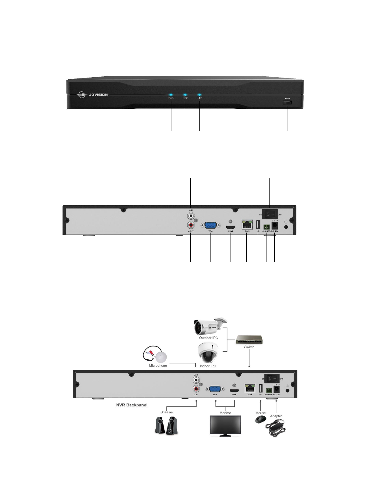
1.2. Front Panel and Rear Panel ......................................................................................................................8
1.3. Connection Sample ..................................................................................................................................8
2. Interface Instruction ....................................................................................................................................9
2.1. Menus.....................................................................................................................................................10
2.2. Live-View Icon.........................................................................................................................................10
3. Startup and Power off................................................................................................................................10
3.1. Boot up...................................................................................................................................................10
3.2. Login .......................................................................................................................................................10
3.3. Power off ................................................................................................................................................11
4. NVR System Configuration.........................................................................................................................11
4.1. Channel...................................................................................................................................................11
4.1.1 Channel...................................................................................................................................................11
4.1.2 Stream ....................................................................................................................................................12
4.1.3 Display ....................................................................................................................................................12
4.1.4 Audio ......................................................................................................................................................13
4.1.5 Image......................................................................................................................................................13
4.1.6 Privacy Mask...........................................................................................................................................14
4.1.7 PTZ..........................................................................................................................................................15
4.1.8 Camera ...................................................................................................................................................16
4.2. Recording and Playback..........................................................................................................................16
4.2.1 Recording................................................................................................................................................16
4.2.2 Playback..................................................................................................................................................17
4.3. Alarm ......................................................................................................................................................17
4.3.1 Motion....................................................................................................................................................17
4.3.2 Video Loss...............................................................................................................................................19
4.3.3 IPC Alarm Input ......................................................................................................................................19
4.3.4 Pre-record...............................................................................................................................................20
4.3.5 Alarm Input.............................................................................................................................................20
4.4. Storage....................................................................................................................................................21
4.4.1 Disk .........................................................................................................................................................21
4.4.1 S.M.A.R.T ................................................................................................................................................21

6
Copyright©2020 Jovision Technology Co., Ltd. All rights reserved.
4.5. Backup ....................................................................................................................................................22
4.4.1 Image Backup .........................................................................................................................................22
4.4.2 Record Backup........................................................................................................................................22
4.6. Network Setup........................................................................................................................................23
4.6.1 TCP/IP .....................................................................................................................................................23
4.6.2 CloudSEE.................................................................................................................................................23
4.6.3 DDNS ......................................................................................................................................................24
4.6.4 Email.......................................................................................................................................................24
4.7. System ....................................................................................................................................................25
4.7.1 General ...................................................................................................................................................25
4.7.2 Date & Time............................................................................................................................................25
4.7.3 User ........................................................................................................................................................26
4.7.4 Features..................................................................................................................................................27
4.7.5 Information.............................................................................................................................................27
4.8. Maintenance ..........................................................................................................................................27
4.8.1 Remote Channel.....................................................................................................................................27
4.8.2 Log ..........................................................................................................................................................28
4.8.3 System ....................................................................................................................................................28
4.8.1 Realtime Rate .........................................................................................................................................29
4.9. IVA..........................................................................................................................................................29
4.9.1 Action Analysis .......................................................................................................................................29
4.9.2 Exception Alarm .....................................................................................................................................31
4.9.3 Statistics..................................................................................................................................................31
4.9.4 Video Detection......................................................................................................................................32
5. Remote Connection ...................................................................................................................................34
5.1. VMS-6100 ...............................................................................................................................................34
5.2. CloudSEE Int’l APP ..................................................................................................................................36
6. Appendix ....................................................................................................................................................38

7
Copyright©2020 Jovision Technology Co., Ltd. All rights reserved.
1. Hardware Installation and Connection
1.1. HDD Installation
Loosen the screws of the
upper cover and side panel,
remove the upper cover.
Model A
Place the HDD in accordance
with the four holes in the
bottom. Fix the hard disk
firmly on the baseboard of
chassis with four screws.
Connect the HDD cable and
power cable.
Model B
Aim the power and data port
of Hard disk at HDD ports on
the DVR motherboard, and
insert it cautiously. Fix the
hard disk firmly on the
baseboard of chassis with
four screws.
Put the cover in accordance
with the clip and then place
the upper cover back, secure
the screws.

8
Copyright©2020 Jovision Technology Co., Ltd. All rights reserved.
1.2. Front Panel and Rear Panel
Note: This model is for reference only, appearance and ports may vary due to different models.
1.3. Connection Sample
①
②
③
④
① Power LED
② HDD LED
③ Network LED
④ USB Port
①
②
③
④
⑤
⑥
⑦
⑧
⑨
① Audio In
② Audio Out
③ VGA
④ HDMI
⑤ RJ45
⑥ USB Port
⑦ RS485
⑧ On/Off Switch
⑨ DC Power

9
Copyright©2020 Jovision Technology Co., Ltd. All rights reserved.
2. Interface Instruction
Connect the NVR to the monitor and then plug mouse and power cable, NVR will boot up and video output will
display. You can use the mouse to implement some simple GUI operation. After device booted up, the system
is in multiple-channel display mode.
Note: The number of displaying channel may vary. The following figure is for reference only.

10
Copyright©2020 Jovision Technology Co., Ltd. All rights reserved.
2.1. Menus
1. Task Bar
Move the mouse to the bottom of the screen, the Task bar will pop-up. You can access the start menu,
Chanel sort, View layouts, Channel auto switch, Network Information, HDD Information and NVR
Information.
2. Right click menu
Right click on the screen, the menu will show. With right click menu, you can access Main menu, Quick
access (Recently used five operations), Screen layouts (Single and Multi), Playback and Backup.
3. Quick access menu
Click on the channel with live video, the Quick access menu will pop-up, in which you can access PTZ,
Instant Playback, Snapshot, Digital Zoom, Volume Control, Record and Camera settings.
4. Main menu
In Main menu, you can access the Channels, Playback, Record, Alarm, Storage, Backup, network, IVS,
System and Maintenance settings.
2.2. Live-View Icon
There will be some icons showing on the channel live view window, which indicate the channel recording
or alarming status. You can refer to the following sheet for channel recording or alarming status
information.
Icon
Instruction
Icon
Instruction
Recording...
Alarm enabled, but not triggered
Connected by remote client
Alarming...
3. Startup and Power off
3.1. Boot up
Make sure all the devices in the environment have been configured and connected properly. Power-on the
NVR. NVR system will search and connect network camera in the environment automatically. After
searching and adding, the system will display live-video of the cameras added.
Notes:
Only when the NVR boot up for first time, or there is no network camera added before, will the NVR search
and add network camera automatically.
3.2. Login
After booting up and connecting the network cameras, the system is in multiple-channel display mode.
You need to login for further operations. Click any item in menu, the Login dialog box appears.
Note: Three consecutive login attempt failure will result system alarm and mouse lock for 30sec.

11
Copyright©2020 Jovision Technology Co., Ltd. All rights reserved.
3.3. Power off
Click the Start menu and navigate to Power You can Logout, Reboot and Shutdown the NVR
system.
4. NVR System Configuration
4.1. Channel
In this Channel Menu, you can manage IP cameras, channel properties and IP Camera display settings etc.
4.1.1 Channel
All the network cameras in the LAN can be automatically detected and listed by NVR. On the Main menu,
click Channel, and Channel management dialog box appears. Click Search to detect all the network
cameras in the LAN.
Select one camera and click Add video source, the camera will be added. Click Add All to add all detected
cameras, but the number of added cameras cannot be more than the limit of NVR. Use Advanced Add to
add ONVIF protocol network camera or add by CloudSEE ID.
Select one added camera and click Delete video source to remove the camera and click Remove All to
delete all added devices.
The NVR will connect camera with default account: admin & 123456, if the account of the camera is not
admin & 123456, the status will display password wrong, please select the camera and click Input Pwd to
input username and password of the camera.
Icon
Instruction
Icon
Instruction
Add video source
Delete video source
Add All
Remove All

12
Copyright©2020 Jovision Technology Co., Ltd. All rights reserved.
4.1.2 Stream
Our network camera supports dual stream for different usage, you can change the video settings for better
performance, network transmission or longer-time storage.
Main Stream: Also called recording stream, used for recording, and if there is one channel full-screen displaying,
this stream will be displayed.
Sub Stream: Also called Second stream or Minor stream, used for the live view if there are multi-channels
displaying.
You can adjust the streaming property (Main Stream Resolution, Bitrate, FPS, Bitrate Control, Coding, Sub
Stream Resolution etc.) of each channel here.
4.1.3 Display
In this menu, you can adjust the OSD and Display settings of each channel.
•OSD
In OSD, you can modify the Channel Name, Name Position, Time Format, Time Position, OSD Font Size
and Advanced OSD options.

13
Copyright©2020 Jovision Technology Co., Ltd. All rights reserved.
•Display
In this setting, you can manage the Icon Position, Live Video Quality and Hide Channels etc.
4.1.4 Audio
If an IP Camera with built-in microphone or an external microphone connected to the IP Camera, you can enable
audio recording or audio monitoring here. Also, you can change the Audio Coding Type and Mic correction
values.
4.1.5 Image
In this Image settings, you can adjust the video display properties of each channels.
•Style: Adjust the image style with three predefined modes. Standard, Soft and Vivid.
•Exposure Mode: There are three exposure modes available. Auto, HLC and BLC.
•Rotation: Support rotate None, 90°, 180°, 270°.
•Max. Exposure: The maximum exposure value you can adjust from 1/3 ~ 1/100000
•Min. Exposure: The minimum exposure value also you can adjust from 1/3 ~ 1/100000
•Day & Night: There are 4 options available. Auto, Color, Black&White. Scheduled Color.
•Light Mode: This option to choose IR LED or bright LED lights in the camera (Support only specific

14
Copyright©2020 Jovision Technology Co., Ltd. All rights reserved.
models)
•Switch Sensitivity: You can adjust the IP Cameras night vision switching sensitivity.
•Brightness: Set the brightness of the video
•Contrast: Set the difference in luminance or color that makes display distinguishable.
•Saturation: Saturation (Chroma) is the colorfulness of a color relative to its own brightness.
•Sharpness: Set the subjective perception of sharpness that is related to the edge contrast of the image.
•AWB, Mirror, Defog, Flip, Low Light Optimize, WDR, Face Mode: These are the additional option to
adjust the IP camera according the scene.
4.1.6 Privacy Mask
This function allows you to cover an area with a black block, both in live view and recording. Supports up to 4~8
private areas. Enable this function and click setting, setting page will appear.
Drag the mouse and draw a rectangle covering the area you want, double-click to confirm. Right click on the
rectangle to cancel the area.

15
Copyright©2020 Jovision Technology Co., Ltd. All rights reserved.
4.1.7 PTZ
There are two ways to access the PTZ (Pan Tilt Zoom) menu in this device. By Quick access menu or by Main
menu.
1. By Quick access menu
Click on the channel with live video, and click the PTZ on the Quick access menu.
2. By Main menu
Click on Main menu -> Channel -> PTZ to access the PTZ controls.
Here you can set PTZ direction, Speed, Focus, Zoom, Iris, Preset, Patrol, Pattern, Watch, Scan, Task and RS485
etc. Please click direction arrows to adjust PTZ position. There are 8 direction arrows. Click + and – to adjust
Zoom, Focus and Iris.
•Preset: Preset is a basic unit in PTZ function, it contains PTZ position and status information, with which
a PTZ camera can turn to the position you set when clicking Call (or go to preset). You can also set a
patrol line with several presets.
•Patrol: You can edit a patrol line with presets and stay time, the PTZ camera can rotate and zoom
according to your setting.
•Pattern: Pattern (Trail) is set a patrol path pattern manually by using direction arrows instead of presets,
the system will remember the path and save it.

16
Copyright©2020 Jovision Technology Co., Ltd. All rights reserved.
•Watch: Watch (Guard) is to set a view position and duration to watch the point.
•Scan: The PTZ cameras can be programmed to move within the configurable PTZ limits (left/right,
up/down). When scan limits are set, the H-Scan, V-Scan, Variable Scan, Random Scan, Frame Scan is
performed only in the limited surveillance area.
•Task: A scheduled task is a preconfigured PTZ action that can be performed automatically at a specific
time.
•RS485: You can set RS485 protocols here. (Please contact the local retailer or PTZ camera provider for
proper settings.). Also, you can swap the PTZ controls here.
4.1.8 Camera
You can vide the IP camera information and Logs. Also, manage IP Camera users update IP camera here.
4.2. Recording and Playback
4.2.1 Recording
Note: After the system booted up, it is in 24-hour regular recording mode by default. If necessary, you can set
record type and time in Record Settings: Main menu -> Record

17
Copyright©2020 Jovision Technology Co., Ltd. All rights reserved.
4.2.2 Playback
Main Menu -> Playback, then system will open video playback interface, shown as below:
Motion detection detects the moving objects in the configured surveillance area, and a series of actions can be
taken when the alarm is triggered.
Click on the date and check-box of the channel needed. Then click on “Play” button. System will start video
playback. Right-click to quit the video playback.
Note: For 16Ch NVR and above Playback, go to Right Click menu-> Playback.
4.3. Alarm
In this menu, you can set and manage alarm related options.
4.3.1 Motion
Motion detection detects the moving objects in the configured surveillance area, and a series of actions can be
taken when the alarm is triggered.
Click Status Switch to enable the function for the channel. Press mouse button and drag to select the area. You
can choose 4 areas at most for one channel. Sensitivity can also be set here. Click OK to save the settings.
You can enable White LED for light up the when motion detects. (It supports only some specific models).

18
Copyright©2020 Jovision Technology Co., Ltd. All rights reserved.
You need to set Alarm Action for each alarm function and channel separately to configure alarm actions the
NVR should take when the alarm is triggered.
•Alarm Duration: Set a time the alarm will last for when the alarm is triggered, the new alarm will not
be triggered until the previous alarm is finished.
•Buzzer: The buzzer inside the NVR will buzz when alarming.
•Send to PC Client: The remote client will alarm when alarming.
•Send Alarm Email: NVR will send alarm E-mail when alarming.
•With Snapshot: NVR will send alarm E-mail with a screenshot when alarming.
•Call Preset: NVR will call preset point when alarming. (For PTZ camera only)
•Start Alarm Recording: NVR will start recording when alarming.
•Trigger Alarm Output: Alarm device connects to NVR will work when alarming. (For some model with
RS-485 port only)
•Trigger Ch.: Select the channel to take alarm action.
You can choose a time range during which the motion detection or no video alarm will be enabled. The alarm
will be disabled automatically in another time period.

19
Copyright©2020 Jovision Technology Co., Ltd. All rights reserved.
4.3.2 Video Loss
Click Status Switch to enable the function for the channel. if the camera is disconnected or lost video, NVR will
alarm.
You need to set Alarm Action to configure alarm actions the NVR to take when the alarm is triggered. Also, you
can schedule the alarm. Please refer to 4.3.1 Motion.
4.3.3 IPC Alarm Input
If the IP Camera support Alarm Input, you can manage the alarm input here.
For Alarm Action and Schedule, please refer to 4.3.1 Motion

20
Copyright©2020 Jovision Technology Co., Ltd. All rights reserved.
4.3.4 Pre-record
Here you can set the amount of time that will be recorded before an event occurs. Click Status Switch to enable
the function for the channel and you can set the Pre-record Length as 10, 30 or 60 Sec.
4.3.5 Alarm Input
In this menu, you can configure and manage NVR alarm input. (It supports only some specific models)
Click Status Switch to enable the function for the channel then select Work Mode. For Alarm Action and
Schedule, please refer to 4.3.1 Motion
This manual suits for next models
4
Table of contents
Popular Network Hardware manuals by other brands

Innodisk
Innodisk SATA Slim 3MG2-P Series manual

Pleora Technologies
Pleora Technologies iPORT Analog-Pro IP Engine user guide

Super Circuits
Super Circuits DMR 1 user guide

Linksys
Linksys VELOP MX5500 Series user guide

ADTRAN
ADTRAN BR1/10 PAU Installation and Maintenance

Viking
Viking DNA-510 Technical practice