JPI EGT-701 User manual

FAA APPROVED INSTALLATION MANUAL FOR THE EGT-701 Report 103
INSTALLING THE EGT-701 SCANNER® 1/20/09 Rev-E
THE OWNER OF THIS EDM-700/800/730/830
MUST KEEP THIS MANUAL
TABLE OF CONTENTS
Page
1) INSTALLING THE INDICATOR 3
2) EXHAUST GAS TEMPERATURE PROBE 3
3) TURBINE INLET TEMPERATURE PROBE 3
4) CYLINDER HEAD TEMPERATURE PROBE 4
5) SPARK PLUG GASKET CHT PROBE 4
6) INDUCTION AIR TEMPERATURE PROBE 4
7) OIL TEMPERATURE PROBE 5
8) OIL PRESSURE TRANSDUCER 7
9) OUTSIDE AIR TEMPERATURE PROBE 7
10) FUEL FLOW OPTION 8
11) WIRING 9
12) EGT AND CHT PROBE WIRING 9
13) ROUTING THE WIRING HARNESS 11
14) MANIFOLD PRESSURE INSTALLATION & CALIBRATION 12
15) RPM SENSOR INSTALLATION 13
16) OPERATING INSTRUCTIONS 14
17) INDICATOR INSTALLATION & RECORD 16
18) ENGINE OPERATION 16
19) LIMITATIONS & OPERATION 16
20) COMPONENT PARTS LIST FOR EGT PROBE 17
21) COMPONENT PARTS LIST FOR CHT PROBE 17
22) COMPONENT PARTS LIST FOR OIL PROBE 17
23) COMPONENT PARTS LIST FOR OAT PROBE 17
24) COMPONENT PARTS LIST FOR MANIFOLD PRESSURE 17
25) COMPONENT PARTS LIST FOR RPM 17
26) COMPONENT PARTS LIST FOR SINGLE ENGINE EGT/CHT 17
27) WEIGHT AND BALANCE DATA 17
28) CHANGING PROGRAMMED LIMITS 18
29) TROUBLE-SHOOTING 20
FIG-1 INSTRUMENT BEZEL TEMPLATE 22
FIG-2 EGT/CHT/TIT PROBE PLACEMENT 23
FIG-3 EGT PROBE INSTALLATION 24
FIG-6 EGT/CHT PICTORIAL LAYOUT 25
FIG-7 WIRING DIAGRAM DRAWING 300701 26
FIG-9 DRAWING 700744 FUEL FLOW WIRING 27
INSTRUCTIONS FOR CONTINUED AIRWORTHINESS (ICA) 28
J.P.INSTRUMENTS Inc.
PO BOX 7033
HUNTINGTON BEACH CA 92646
FAA APPROVED 10-28-09
Last printed 05/16/13

FAA APPROVED INSTALLATION MANUAL FOR THE EGT-701 Report 103
INSTALLING THE EGT-701 SCANNER® 1/20/09 Rev-E Page 2 of 30
READ THIS FIRST
The following notes apply to a new installation. Read this section before proceeding.
a) The JPI warranty found in the back of the pilots guide clearly states that JPI will replace defective parts
under warranty, but does NOT cover labor to remove or install any parts.
b) To prevent damage to the display it is essential that the four mounting screws not penetrate the
instrument more than 0.12 inches. Damage caused by screw penetration is not covered under
warranty.
c) You must be an FAA certified aircraft mechanic to install this instrument.
d) Check that any necessary FAA approvals (STC’s, etc) are available for the aircraft before beginning the
installation.
e) The most common cause of probe problems is poor terminal crimps. Crimp ring terminals with AMP part
45518 crimp tool or equivalent. Fold back the wire double before crimping terminals.
1/4" 1 1/2"
Fold back wire
double before
crimping terminals
2 1/4"
Thermocouple wire harness
red
yellow
f) This installation will require some parts unique to your aircraft that are not supplied with the kit,
(including but not limited to tie-wraps, hoses and fittings). Acquire all the necessary parts prior to
beginning the installation.
g) Do NOT use aluminum fittings with the FXT-201 or FXT-231 fuel flow transducer.
h) Write down the K-factor engraved on the side of the fuel flow transducer here _______. Once the
transducer is installed and covered with the fire sleeve, you will not be able to access this K factor.
i) Determine the locations of all holes before drilling to ensure that nothing interferes with the probe,
clamp, clamp screw or wire.
j) Provide service loops at the instrument.
k) Thermocouple wire length is not critical. Trim to required length, allowing for service loops at the engine
so that probes can be swapped with probes on adjacent cylinders for troubleshooting purposes.
l) Dress all wires away from high temperature components such as exhaust stacks.
m) Never splice thermocouple wire using copper wire. Use only K-type thermocouple wire. Solder using
zinc chloride flux such as Nokorode brand – rosin flux alone won’t work.
n) Observe correct polarity on all probe wires. Connect like colors together (red to red, yellow to yellow).
o) This instrument must be grounded at the engine, not at the avionics ground.
p) If a spark plug gasket probe is used, expect the CHT reading on that cylinder to be somewhat higher
than on the cylinders with bayonet probes. At additional cost an adapter probe (bayonet or screw-in) is
available that permits the factory CHT probe and the JPI probe to be placed in the same bayonet
location.

FAA APPROVED INSTALLATION MANUAL FOR THE EGT-701 Report 103
INSTALLING THE EGT-701 SCANNER® 1/20/09 Rev-E Page 3 of 30
1) INSTALLING THE INDICATOR Installation
Should Be Done In Accordance With Advisory Circular AC43.13-1A. All Models have the same basic
Part No. EGT-701 ( ).
EDM-700/800 Model :A steel template supplied with the installation kit is used as a guide for drilling two button holes
in the instrument panel. Align and Mount the Template into the instrument panel hole. First drilling a 0.125 hole.
Remove the template and check the instrument alignment, if OK redrill with a 0.147 drill. Buttons can be removed by
pulling off. The EGT-701 mounts in a standard 2.25” or 3 1/8” instrument hole. The instrument configures itself
automatically for 4 to 9 cylinders, 14/28 volt aircraft. The instrument is 7.5” deep less connectors and is 2.6 square
behind the panel.
TO PREVENT DISPLAY DAMAGE IT IS ESSENTIAL THAT THE FOUR MOUNTING SCREWS NOT PENETRATE
THE INSTRUMENT MORE THAN .12 INCHES.
DAMAGE OF THIS NATURE IS NOT COVERED UNDER WARRANTY.
EDM-730/830 Model: Mounts in a standard 3.1/8” instrument hole. First place the mounting bracket on the
instrument and tighten the clamp hex screw until you can just remove the instrument from the bracket. The Mounting
bracket is then placed behind the instrument panel hole and screwed (6-32 x ½” screws) in place using the existing
holes. Three screws should be used leaving one hole vacant on either side of the hex screw. Locate the hex screw in
a location that you can easily get to from the rear of the panel. The body of the instrument is 3.0 inches and 2.0 inches
deep less connectors. The body of the instrument is 3.0 inches and 2.0 inches deep less connectors.
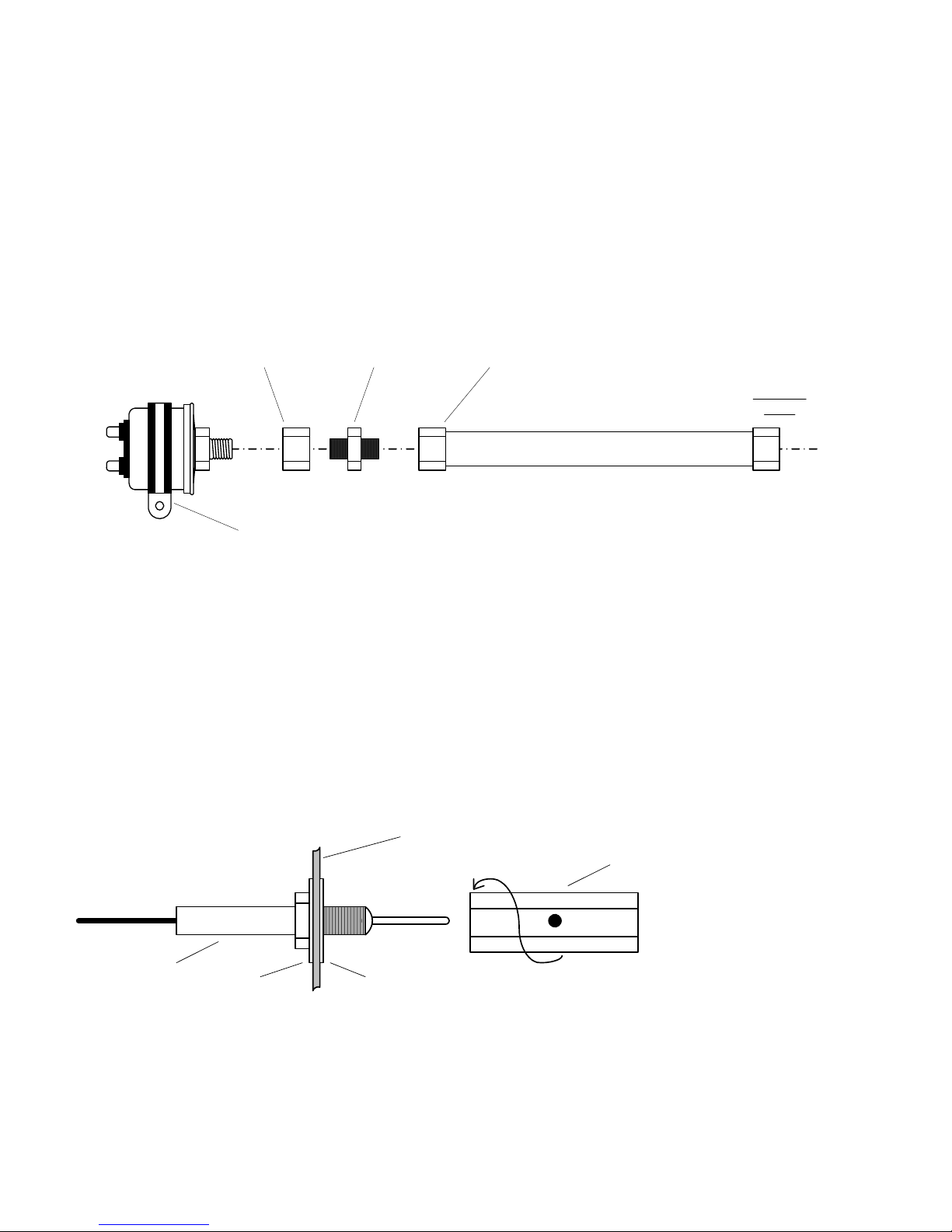
2) EXHAUST GAS TEMPERATURE PROBE (EGT)
The Model M-111 Probe will fit any existing holes in the exhaust stack in any engine having the diameter of 1/8" to
1/4". If no hole exists, it will require the drilling of a 1/8" diameter hole and ream to fit. It is important that each probe
be mounted a uniform distance from the exhaust stack flange. A nominal distance of 2 to 4 inches from the exhaust
flange is recommended. (See fig-2). If the recommended distance is impractical because of obstructions, slip joints or
bends in the exhaust system then position the probes a uniform distance from the flange as space permits. Be
certain to locate all holes BEFORE drilling to ensure that nothing interferes with the probe, clamp, clamp screw or wire.
Careful matching of probe position will provide best temperature readings. Insert the probe in the exhaust or
previously drilled hole (see fig-3) so that the tip of the probe is in the center of the exhaust stream. Tighten the
stainless steel clamp to a torque of 45 in/Lbs. Cut off the excess strap close to the screw. Probe warranty is void if
mounted in a slip-joint of any kind.
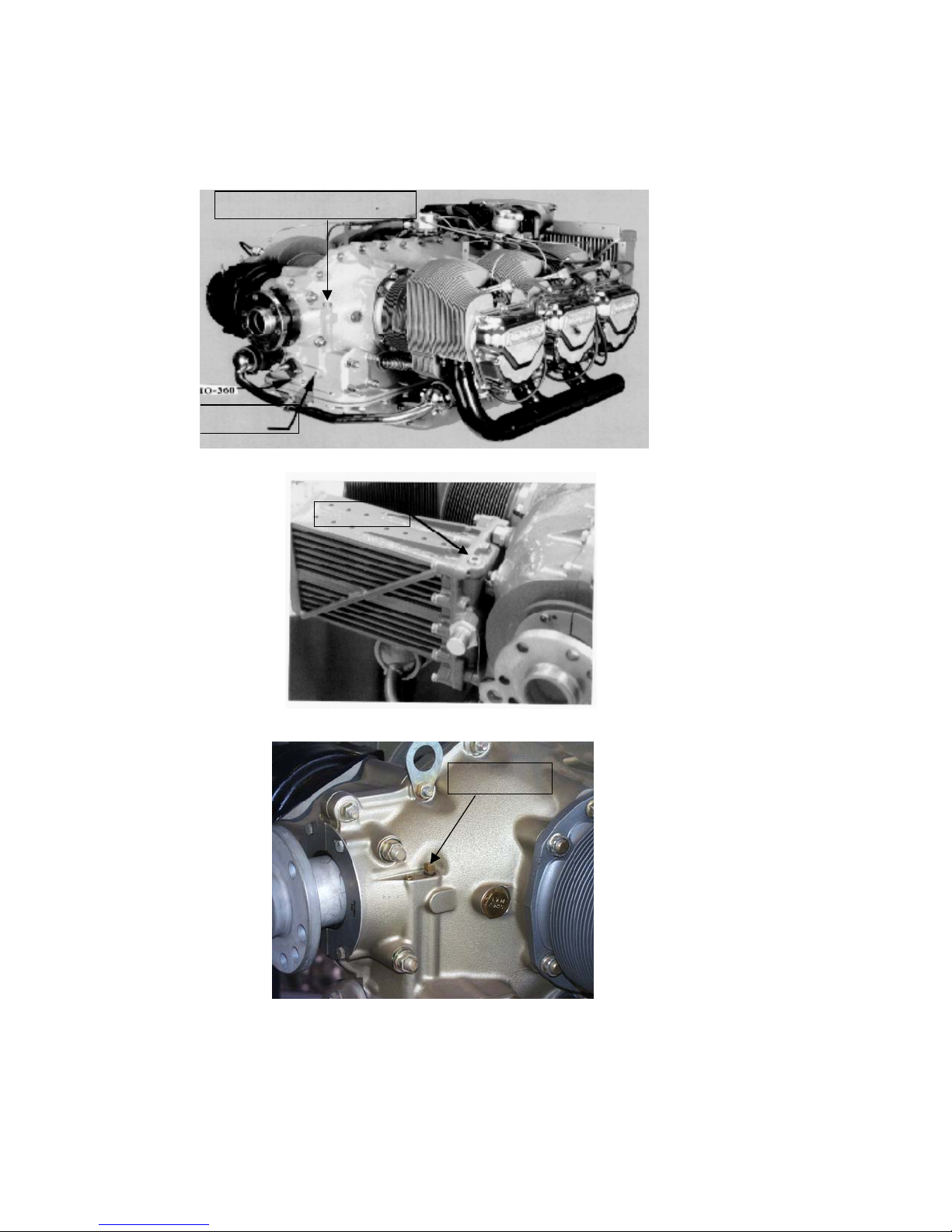
RADIAL ENGINES , EGT
Radial engine exhaust, require a larger EGT clamp (supplied) to fit the 2.5 inch exhaust pipe. The EGT probe is
installed in the same fashion as a Lycoming or Continental engine and should be placed between the exhaust pipe
flange and the accumulator at a distance of 2 to 3 inches form the engine exhaust flange. Cylinder head temperatures
are measured with a spark plug gasket type probe placed under the front sparkplugs. Refer to the engine
manufactures red line and set the EDM-700 appropriately. Front spark plugs will read 15 to 20 degrees cooler than
the rear plugs. Do not route the EGT/CHT harness in with the ignition harness. Do not extend the yellow
thermocouple leads with copper wire.
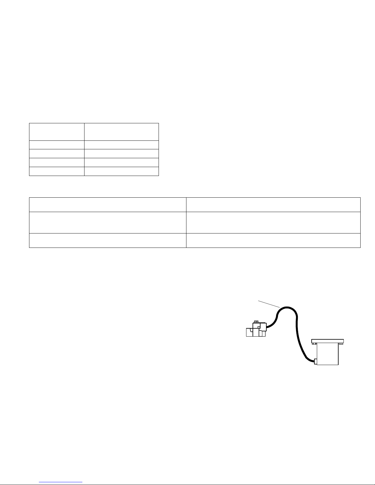
3) TURBINE INLET TEMPERATURE PROBE (TIT)
The standard TIT probe P/N M-111-T with a special clamp is placed in the exhaust stack accumulator to a maximum
depth of 1/2 inch and approximately four (4) inches from the Turbine inlet if possible, on the wastgate side of the
turbine. TIT will appear as the seventh column “T “and the expression “1650 TIT” will be seen when the dot is in place
over it. The EDM-700 input is also compatible with the aircraft’s factory TIT and may be piggy backed.
The EDM-700 TIT cable may be connected in parallel (piggyback) at the TIT probe (preferred), or at the ship's TIT
gage. Check the TIT readings between the EDM and the ships TIT gage in flight, then do the following calibration
procedure. (This may be done in flight or on the ground.)

FAA APPROVED INSTALLATION MANUAL FOR THE EGT-701 Report 103
INSTALLING THE EGT-701 SCANNER® 1/20/09 Rev-E Page 4 of 30
Press & hold 'STEP' and 'LF' keys simultaneously until you see
'PROGRAM' and 'RATE 4'. (Note: Bargraph disappears)
Now press & hold 'STEP' and 'LF' simultaneously again until you see
'ORIG. TIT' and 'ORIG. T-N'.
Tap 'LF' once to change to
'ORIG. T-Y'.
Tap 'STEP' once to display
'CAL TIT' and 'TIT+ 0'.
This is the correction added to (+), or subtracted from (-) the EDM reading for TIT (at high temperatures).
Hold in 'LF' to raise the correction, or tap 'LF' to lower it.
For example, if the EDM read 100 less than the ship's TIT,
Then hold in 'LF' until you see
'TIT+100'.
Adjust the correction slightly if a difference between the EDM
and the ship's gage still exists.
Now tap 'STEP' once to complete setup.
4) CYLINDER HEAD TEMPERATURE PROBE (CHT), BAYONET
The Bayonet probe 5050-T has the 3/8-24 adaptor boss as part of the probe and is screwed into the base of the
cylinder (See fig-2). The bayonet probe has a screwdriver slot to facilitate tightening.
NOTE: Required original equipment that has a Red Line may not be replaced by the EGT-701 TIT or CHT installation.
This includes but is not limited to all aircraft with adjustable cowl flaps and on aircraft with placards on the instrument
panel showing a climb air speed, for cooling, different from the best rate of climb air speed.
If a previously installed TIT, CHT or EGT is listed on the aircraft equipment list as Optional Equipment or not listed at
all, it may be replaced by the EGT/CHT SCANNER.
5) CYLINDER HEAD TEMPERATURE PROBE (CHT) SPARK PLUG GASKET
Most factory installed cylinder head temperature gauges utilize a bayonet or screw-in resistive type probe that
occupies one of the bayonet sockets. This probe is not compatible with the thermocouple probes required for the
EGT-701.
The spark plug gasket probe, P/N M-113, replaces the standard copper spark plug gasket on one spark plug. The
plug chosen, upper or lower, should be the one that provides the best correlation with the other temperature probes.
Due to the spark plug location, the gasket probe may read 25oF higher or lower than the factory probe. The probe is
usually placed on the plug that receives the most direct cooling air. After many removals the probe may be annealed
for re-use. Heat and quench in water. At additional cost an adapter probe P/N M-113-3/8 is available that permits the
factory CHT probe and a JPI probe to fit the same bayonet location.
6) INDUCTION AIR TEMPERATURE PROBE (IAT) / CARB TEMP.
Induction Air temperature probe, IAT, is installed just after the inter-cooler (OUT) and the Compressor Discharge
Temp (CDT) just before the inter-cooler (IN). The probe is an EGT probe and installed the same way as an EGT
probe. A large clamp is supplied to fit around the airport leaving the inter-cooler or a 1/8 NPT is available. IAT option
is displayed as an independent digital temperature like "125 IAT". On non-turbo engines the IAT in reality is the
Carburetor temperature and displayed as “34 CRB”.

FAA APPROVED INSTALLATION MANUAL FOR THE EGT-701 Report 103
INSTALLING THE EGT-701 SCANNER® 1/20/09 Rev-E Page 5 of 30
7) OIL TEMPERATURE PROBE
The Oil Temperature Probe PN 400505-C or 400505-L is installed as a supplemental oil temperature indicator.
Lycoming Engines: The -L part number is for all Lycoming direct drive engines and is installed in the right (passenger
side) front oil galley by removing the existing 1/8 NPT plug on the passenger side of the engine and inserting the
optional JPI oil probe supplied with the kit. Oil temperature will be displayed as an independent temperature like "230
OIL" and will be displayed In the seventh column automatically if TIT is not available. The original oil temperature
gauge and sensor must remain. Check for oil leaks and safety wire before first flight.
Oil Probe Location Alternate Oil Probe
Location
Lycoming Engines
front view
Continental Engines: The -C part number is for all Continental direct drive engines and is installed in the left (pilot
side) front oil galley by removing the existing 3/8 or 1/8 inch NPT plug (see figure below) located on the front, pilots
side of the engine. Insert the optional JPI oil probe supplied in the kit. For 3/8 inch NPT installations, use the supplied
brass adapter. An alternate location is on the top, front of the engine on the pilot’s side, where the probe is inserted
vertically. There are two 1/8 NPT plugs close together. Install the probe in the position that is above and to the rear of
the nearby position.
Alternate Oil Probe
Location
Oil Probe Location
Continental Engines
Alternate Oil Probe
Location
front view

FAA APPROVED INSTALLATION MANUAL FOR THE EGT-701 Report 103
INSTALLING THE EGT-701 SCANNER® 1/20/09 Rev-E Page 6 of 30
Continental Engines Oil probe location
Std oil IO-360
A
lt location IO-520/550
IO-360
Alt location
O-470
Requires ¼NPT to 1/8 NPT reducer Oil reports after thermostat opens
IO-520/550
The oil probe P/N 400505-C is installed by removing the 3/8 or 1/8 pipe plug located on the front of the engine inline
with the push rods. This oil galley feeds the valve lifters. Insert the JPI 1/8 NPT probe supplied with the kit. Check for
leaks after installation. Due to cowling restrictions the alternate oil location may be chosen. The probe leads are
routed back to the cockpit along with the EGT wires. Do not install the Oil Probe in the rear of the engine near the
vernatherm (oil temperature regulator).
Alternate Oil
Location
IO-520/550

FAA APPROVED INSTALLATION MANUAL FOR THE EGT-701 Report 103
INSTALLING THE EGT-701 SCANNER® 1/20/09 Rev-E Page 7 of 30
8) Oil Pressure Sensor Installation
Use the J3 connector harness 790420 labeled OIL-P for a VDO pressure sensor (shown in diagram below). Oil
pressure sensor mounts using an aluminum clamp MS21919. Mount to firewall or tie wrap to existing wiring bundle.
Mount the pressure sensor to the pressure line using a flexible hose and fittings (not supplied) as depicted in the
drawing below. Use aluminum clamp to mount the pressure sensor to firewall. Do not mount the sensor directly to
the engine. Connect the other end of the hose to the engine manufacturer’s recommended location for engine oil
pressure. An alternate method of installation is to install a T-fitting (not supplied) in the aircraft’s oil pressure gage line
in the cockpit near the oil pressure gage. Their is no polarity on the oil pressure transducer wires.
9) OUTSIDE AIR TEMPERATURE PROBE, OAT
Install the OAT probe, P/N 400510 in the airframe manufactures recommended location. If this is not possible, it is
recommended that the OAT probe be placed in clean airflow such as in a cabin air scoop or below the underside of
the wing away from engine heat or exhaust. In this case it is recommended that the installation be done similar to the
antenna installation instructions of AC 43.12-2a "Acceptable Methods, Techniques and Practices". The outside
aluminum tube is used to both hold the probe in place and shield it from radiated heat. OAT option is displayed as an
independent digital temperature like "75 OAT". Be sure that when testing the OAT it is not in direct sun and the engine
is running.
washer
aircraft sheet metal
washer
probe
shield tube
used to secure
probe
flexible tube 6 inch (AEROQUIP 303)
AN-910-1D
1/8 NPT coupling
AN-816-4D
1/8 NPT to flared
MIL-H-8794 hose
MS-24587 fitting (AEROQUIP 491, 2 req'd)
to engine
fitting
DO NOT MOUNT SENSOR DIRECTLY TO ENGINE
Transducer supplied by JPI, all other hardware supplied by
installer.
pressure
sensor
mount using
MS21919 -DG24
1.5 inch clamp
PN 30601

FAA APPROVED INSTALLATION MANUAL FOR THE EGT-701 Report 103
INSTALLING THE EGT-701 SCANNER® 1/20/09 Rev-E Page 8 of 30
10) FUEL FLOW OPTION
The EGT-701 receives signal from any installed Flowscan Transducer of the following Flowscan P/N’s embossed on to
the top of the transducer. The K-Factor is engraved on the side of the Transducer. Wire per drawing 700744, Route
the JPI wires along the existing wiring bundle lacing every foot.
Flowscan Instruments, Seattle WA 98106
FlowScan PN Shadin equivalent
PN
201-A
201-B 680501/680600
201-C
231 680503
Install the function switch in the panel per drawing 700124.
Select the appropriate installation configuration from the three following fuel system categories:
For gravity feed systems without a fuel pump use transducer FXT-231 (yellow plastic top). Connect the
transducer between the fuel tank and carburetor.
For pump feed or fuel injected systems without
vapor return lines
use transducer FXT-201 (black plastic top). Connect the
transducer between the engine driven pump and
servo/throttle body or carburetor.
For all fuel injected engines with vapor return
lines to the fuel tank before the servo/throttle.
use transducer FXT-201 (black plastic top). Connect the
transducer between the throttle body and the fuel flow divider.
The transducer output port should be mounted lower or level with the carburetor inlet port (or fuel servo on a fuel
injected engine). If this is not possible, an anti-siphon loop should be put in the fuel line between the fuel flow
transducer and the carburetor or fuel servo.
Find a convenient location within 8 inches of a
hose support or fitting to suspend the fuel flow
transducer. Mount it away from any hot exhaust
pipes. The hose support or fitting may be on the
input or output line of the fuel flow transducer.
Secure the end of the transducer to any
convenient point on the engine with MS21919
clamps or equivalent. Do not place an
angled elbow joint immediately
prior to the input port of the fuel
flow transducer. There should be two
inches of straight flow immediately before the transducer input port.
For a carbureted engine: remove the fuel hose which connects the carburetor to the fuel tank. Purchase two new
hoses — one to connect the carburetor to the fuel flow transducer, and the other to connect the fuel flow transducer to
the fuel tank. Before connecting the fuel hose to the carburetor, verify that the boost pump delivers at least 125
percent of takeoff fuel flow at minimum fuel pressure as marked on the fuel pressure gage.
For a pump-fed carbureted or fuel injected engine without vapor return lines: remove the fuel hose which
connects the engine-driven pump and the servo/throttle body or the carburetor. Purchase two new hoses one to
connect the engine-driven pump to the fuel flow transducer, and the other to connect the fuel flow transducer to the
servo/throttle body or the carburetor.
For a fuel injected engine with vapor return lines before the servo/throttle: remove the fuel hose which connects the
throttle body and the flow divider. Purchase two new hoses one to connect the throttle body to the fuel flow transducer,
and the other to connect the fuel flow transducer to the flow divider. For Continental fuel injected engines adjust the
fuel pressure to account for the pressure drop across the transducer per Continental Service Bulletin M89-10.
IN
OUT
carburetor
or servo
transducer
If the transducer is higher than the
carburetor or fuel servo, put a loop
between the transducer and carburetor
or servo
SIDE VIEW

FAA APPROVED INSTALLATION MANUAL FOR THE EGT-701 Report 103
INSTALLING THE EGT-701 SCANNER® 1/20/09 Rev-E Page 9 of 30
There must be flexible hose into and out of the fuel flow transducer. The hoses must meet TSO-C53a type C or D FAA
specification. The new hoses must be the same size as the current hose in the aircraft. The fuel flow transducer must
be wrapped with fire sleeving. Cut a 1 inch slit in the center of the fire sleeve and pass the transducer connector and
cable through it. Seal with high temperature silicone RTV sealant.
The placard “Do not rely on fuel flow instrument to determine fuel levels in tanks” must be mounted on the
aircraft instrument panel near the EGT-701. If the aircraft is equipped with a primary fuel flow instrument, the following
placard must be mounted on the aircraft instrument panel near the EGT-701 “Refer to original fuel flow
instrumentation for primary information.”
11) WIRING (12 / 24 volt)
The EGT-701 automatically accommodates both 14 and 28 volt electrical systems. Connect the power lead (red) to a
separate 5 amp circuit breaker (or 2 amp slow blow in-line fuse) connected to the avionics power buss. The avionics
master switch will then be used to turn off the instrument during engine start-up. The EDM-700 has a 10-second
warm-up. If the panel lacks an avionics master switch we recommend that one be installed or a circuit breaker switch
be provided to turn off the EGT-701 during engine start-up. If the voltage fall below 9.8 vdc the instrument will turn off
automatically. The Instrument should be grounded at the engine. No connection to the aircraft dimmer system is
required because the instrument dims automatically with reductions in ambient light.
12) EGT and CHT Probe Wiring
The EGT-701 is supplied with special Teflon insulated Chromel Alumel factory assembled wiring harness configured
for the correct number of cylinders. The wire harness is marked E-1= EGT-1, C-1= CHT-1, etc. TIT is marked “T”,
Oil I = “O” and OAT = “A”. For retrofits of the EGT-100 SCANNER or bar graph instruments, where only the
indicators are being exchanged, the old harness wires need to be pinned with AMP P/N 665049 and fitted into AMP
D-SUB connector P/N 205207-1 with hood per drawing 300701 fig-6 or connected directly via an adapter connector.
NOTE: Unlike most other EGT & CHT installations the probe wire length is not critical and should be trimmed to any
length as required for a clean installation.
The Temperature probes must be wired with the correct polarity. Each wire is marked with the cylinder number. The
EGT and CHT probes connect to the temperature indicator with yellow jacket Teflon Chromel Alumel wire supplied.
Strip the wires according to drawing 5057 and terminate with the crimp-on ring terminals provided. Verify the quality of
each crimp with a sharp pull on the wire. The terminal should be almost impossible to pull off when crimped correctly.
With in a few inches of the instrument terminal strip a connector may be installed.
NOTE: The ring terminals may be crimped with a “service type” tool, however AMP part number 48518 tool is
recommended. Be sure to test each crimp by pulling on the wire to assure it will not come out.
The most common installation problems are poor quality terminations.
The EGT-701 must be grounded to the engine block, not at a ground point under the instrument panel. No
connection to the aircraft dimmer system is required or permitted because the instrument dims automatically with
reductions in ambient light.
Install the data port connector in the instrument panel. This is the 2.5 mm ID, 5.5 mm OD on the
twisted white and black wires on J1. See Installing the Instrument section earlier in this manual.

FAA APPROVED INSTALLATION MANUAL FOR THE EGT-701 Report 103
INSTALLING THE EGT-701 SCANNER® 1/20/09 Rev-E Page 10 of 30
Before you begin, note that the most common cause of probe problems is poor
terminal crimps.
When cutting each pair of leads in the wiring harness to the proper length to connect to the probes, leave enough
slack in the harness so that probes from adjacent cylinders may be interchanged if necessary for trouble-shooting and
servicing. Thermocouple wire length is not critical and should be trimmed to any length as required for a clean
installation.
The Temperature probes must be wired with the correct polarity. Each wire is marked with the cylinder number. The
EGT and CHT probes connect to the temperature indicator with yellow jacket Teflon Chromel Alumel wire supplied.
Strip the wires as shown below, observing color codes. Important: fold back the wire double before
crimping terminals.
1/4" 1 1/2"
Fold back wire
double before
crimping terminals
2 1/4"
Thermocouple wire harness
red
yellow
Terminate each wire with a crimp-on ring terminal, provided. The ring terminals may be crimped with a “service-type”
tool, however AMP part number 48518 crimp tool is recommended. Verify the quality of each crimp with a sharp tug on
the wire. The terminal should be impossible to pull off when crimped correctly.
shrink tubing
shrink tubing
ring terminal
Place a ¼x 4 inch sleeve over each pair of wires in the harness. Connect the harness ring terminal to the probe ring
terminal using the supplied number 4 screws and nuts, placing the star washer between the ring terminals, not against
the nut.
Important: place star waster between two ring
terminals and tighten nut and bolt as
necessary
to instrument
to probe
Slide the sleeve over the joint and secure with three tie-wraps.
1/4 x 4" sleeve
tie-wrap 3 places
Cut red lead if
transducer is
also connected
to another fuel
flow instrument
IN
OUT
WHT
BLK
RED
WHT
BLK
RED
fuel flow option
connector
1
1
9
8
15
FF
COM
EGT
+12/24 avionic bus
GPS
RS-232 input to EDM-700
GPS output
GPS input
(some KLN series only)
RS-232
output from
EDM-700
8
7
6
5
4
3
2
1
Fuel Flow Transducer
FloScan 201 -A, -B, -C, or 231
Alarm lamp or enunciator
(customer supplied option)
11
9
panel
mounted
switch
(alarm wire not supplied)
EGT
ALL
FF

FAA APPROVED INSTALLATION MANUAL FOR THE EGT-701 Report 103
INSTALLING THE EGT-701 SCANNER® 1/20/09 Rev-E Page 11 of 30
13) ROUTING THE WIRING HARNESS
Route the wires from the probes and sensors through the firewall using fireproof rubber grommets and flame retarding
silicone. Use an existing hole if possible. Following the existing wiring harness and connect to the indicator marking
each lead with the cylinder number. All wires must be routed away from high temperature areas (exhaust stacks,
turbochargers, etc.). Secure Probe leads to a convenient location on the engine approximately 8 to 12 inches from the
probe, being sure there is sufficient slack to absorb engine torque. It is essential in routing the probe wire that this
wire not be allowed to touch metal parts of the airframe or engine since abrasion will destroy this high temperature
wire.
Connect the JPI RPM sensor to the wiring harness using the 3-pin connector supplied.
Secure thermocouple wires along the route to the indicator. Secure wire using original clamps, tie wrap if possible.
CAUTION: Be sure the wiring does not obstruct the controls under the panel.
The probe wires must not be tied in with ignition, alternator or twin engine cabin heater ignition wires because of
potential interference with temperature readings.
Temperature probe wiring harness is made of Chromel-Alumel alloy wire (yellow) that must not be substituted or
extended with normal copper wire. The power and ground wire are normal copper. Leads may be spliced with
additional Chromel-Alumel wire using copper butt splices.
When the installation is complete all wires should be secured using ties and carefully checked for interference,
rubbing or chaffing with flight control cables or other moving parts.

FAA APPROVED INSTALLATION MANUAL FOR THE EGT-701 Report 103
INSTALLING THE EGT-701 SCANNER® 1/20/09 Rev-E Page 12 of 30
from engine
MP Sensor
T-fitting
connector
MP gage
14) Manifold Pressure (MP) Sensor
Install a T-fitting (not supplied) in the aircraft’s MP gage line in the cockpit near the MP gage. Install the JPI MAP
sensor
P/N 604010 on the T-fitting. Connect the JPI MP sensor to the wiring harness using the 4-pin connector supplied. The
MAP sensor uses a 1/8 NPT fitting. Note: this is eligible for installation on all 4 & 6 cylinder engines only. There are
no alarm limits.
Manifold Pressure Calibration
The manifold pressure must be calibrated to the ambient air pressure. Enter the current ambient barometric pressure. The engine
must not be running. This setting is not the same as the altimeter setting that you receive from ATIS or unicom. It will vary with
field elevation. Use the chart below to calculate the MP FACTOR. Multiply this MP FACTOR by the altimeter setting that you
receive from ATIS or unicom. For example if the field elevation is 1700 ft and the altimeter setting is 30.1, the MP FACTOR is
0.9400 from the table. Multiply 30.1 x 0.9400 to get the ambient MP of 28.29.
Field Elev MP FACTOR
-500 1.0182
-400 1.0145
-300 1.0109
-200 1.0073
-100 1.0036
0 1.0000
100 0.9964
200 0.9928
300 0.9892
400 0.9856
500 0.9821
600 0.9785
700 0.9750
800 0.9714
900 0.9679
1000 0.9644
1100 0.9609
1200 0.9574
1300 0.9539
1400 0.9504
1500 0.9469
1600 0.9435
1700 0.9400
1800 0.9366
1900 0.9332
2000 0.9298
2100 0.9264
2200 0.9230
2300 0.9196
2400 0.9162
2500 0.9129
2600 0.9095
2700 0.9062
2800 0.9028
2900 0.8995
3000 0.8962
3100 0.8929
3200 0.8896
3300 0.8863
3400 0.8830
3500 0.8798
3600 0.8765
3700 0.8733
3800 0.8700
3900 0.8668
4000 0.8636
4100 0.8604
4200 0.8572
4300 0.8540
4400 0.8508
4500 0.8477
4600 0.8445
4700 0.8414
4800 0.8382
4900 0.8351
5000 0.8320
5100 0.8289
5200 0.8258
5300 0.8227
5400 0.8196
5500 0.8165
5600 0.8135
5700 0.8104
5800 0.8074
5900 0.8043
6000 0.8013
6100 0.7983
6200 0.7953
6300 0.7923
6400 0.7893
6500 0.7863
6600 0.7833
6700 0.7804

FAA APPROVED INSTALLATION MANUAL FOR THE EGT-701 Report 103
INSTALLING THE EGT-701 SCANNER® 1/20/09 Rev-E Page 13 of 30
15) RPM Sensor installation
There are four types of magnetos commonly in use. You must have the correct RPM sensor for the magneto installed
in the aircraft. The following part numbers apply: Slick – pressurized 4000, -6000 series use JPI P/N 420809. For the
Bendix pressurized -1200 series use P/N 420807. Dual magnetos use JPI PN 420808. For the Bendix -20 series and
Slick 600 use JPI P/N 420806. Mount the sensor as shown in the appropriate diagram below. Note: this is eligible for
installation on all 4 & 6 cylinder engines only.
Bendix Magnetos Slick Magnetos
Bendix Dual Magneto
JPI PN 420808
non-pressurized
engine
Mount sensor side of bracket towards
magneto body
Bendix -20, -21, -200, 1200 series
non-pressurized
JPI 420815-2
Connector to harness
engine
Connector to harness
Slick 6000, 4000 series
pressurized
JPI 420809
engine
TOP
Sensor ring munted under vent plug.
Stem at right angles to magneto center line
Mount sensor side of bracket towards
magneto body
Alternate bracket location
Vent plug
Spacer ring
Sensor ring bracket
Magneto body
Connector to harness
Slick 6000, 4000 series
non-pressurized
JPI 420815-1
engine
Bendix 1200 series
pressurized
JPI 420807
Connector to harness
engine
Alternate bracket locations
TOP
position limit
position limit
Mount sensor side of bracket towards
magneto body, positioned over the magnet
armature
rev Dec 2010
engine
Slick 600 series
JPI PN 420806
non-pressurized
Sensor must be over
moving magnet armature
Remove this screw
to mount sensor
bracket

FAA APPROVED INSTALLATION MANUAL FOR THE EGT-701 Report 103
INSTALLING THE EGT-701 SCANNER® 1/20/09 Rev-E Page 14 of 30
16) DESCRIPTION / OPERATING INSTRUCTIONS
The EGT-701 temperature indicator displays temperature digitally and in analog format. The EGT as displayed is
based on probes located near the exhaust outlet for each cylinder and the TIT probe, if installed, is adjacent to the
turbo charger. These probes are not necessarily collocated with the primary probes therefore; EGT-701 may not
indicate the same as the aircraft primary instruments. The analog display is an electronic bar graph (vertical columns,
one per cylinder) of EGT & TIT temperatures presented as a percentage of 1650oF. Below the vertical columns the
specific value for EGT and CHT are displayed digitally. The dot over the column indicates which cylinder’s digital
information is presently displayed. The missing bars at the base of the columns indicate the hottest and coldest
Cylinder Head temperature trend. During Lean Find mode the leanest cylinder is displayed along with the fuel flow
(optional) at that time. Depressing the LF and STEP button simultaneously brings up the adjustable scan rate
function, OAT in oC or oF. Depress the LF button will change the value of the rate or Oat in oC or oF. Exit by
Depressing STEP.
If the EGT-701 buttons are not depressed for 10 minutes the system will start scanning automatically. Depressing the
STEP button will stop the automatic scan and index through all the functions available. During constant power cruise,
if the LF button is depressed for five seconds the Bargraph will level at mid scale. The leveled bars represent the
peaks of each column. Each bar represents 10 oF and now acts as an EGT & TIT trend monitor, quickly showing an
increase or decrease in temperature. Depress again to return to normal; nothing else is affected. With the fuel flow
option there is a three position toggle switch. The positions are: 1) EGT, digital and Bargraph display of temperatures,
2) FF, digital display of GPH, REM and USED Fuel. Temperature Bargraph remains. 3) Both, cycles through
everything installed. The data port output sends RS232 serial data every 6-sec.
Options of Fuel Flow, TIT, OAT, IAT (induction air temp.), OIL, BAT (voltage) and are displayed digitally with headlines
after the number, as “230 OIL” or “14 GPH”. A large value (50 +) of “CLD” indicates shock cooling usually associated
with rapid descents at low power. Optional functions not installed will not display. The same acronyms are
incorporated in the TFT flat panel display.
EDM-800 Plasma display
RPM 2700
CH 376 F
EGT 1340 F
switc

FAA APPROVED INSTALLATION MANUAL FOR THE EGT-701 Report 103
INSTALLING THE EGT-701 SCANNER® 1/20/09 Rev-E Page 15 of 30
EDM-830 TFT Flat panel display
Portrait
EDM-830 TFT Flat panel display
Landscape
EDM-830 system mounts in a 3.125 inch instrument panel hole in either a portrait or landscape position
depending on panel hole location.
By holding the Step button (white) for approx. 10 seconds and arrow will appear on the display showing
which way is up. Use the LF button to index the arrow. When the proper position is achieved, press the
step button and the system will reboot in the direction chosen.
switc
switc

FAA APPROVED INSTALLATION MANUAL FOR THE EGT-701 Report 103
INSTALLING THE EGT-701 SCANNER® 1/20/09 Rev-E Page 16 of 30
17)Installation Record
The indicator and probes FAA TSO approved, as a temperature indicator under TSO-C43b. Record the
installation of the EGT-701 per STC# SA 2586NM. Make an appropriate entry in the aircraft log book. FAA form 337
may be required.
18)Operation
Airplane flight manual limitations based on primary instrument indication take precedence over those of the EGT-701.
CAUTION: Comply with manufacturer’s airplane/rotorcraft flight manual leaning procedure. Do not exceed
applicable engine or aircraft limitations.
CAUTION
Complywithmanufacturer’sAirplane/Rotorcraft
FlightManualleaningprocedure.
Donotexceedapplicableengine
oraircraftlimitations.
After establishing desired cruise power depress the LF button to activate the Lean Find Mode. As the mixture is
leaned, the column display on the EGT-701 for one cylinder will begin blinking; indicating the exhaust gas temperature
for that cylinder has peaked. Continue with the leaning procedure as recommended by the aircraft manufacturer while
monitoring the primary engine instruments and the EGT-701 display. Once the leaning procedure has been
completed, depress the Step button briefly to exit the Lean Find Mode and enter the Monitor Mode.
ENGINE OPERATION: Operate and lean the engine in accordance with the manufacturers’ recommendations
for different power settings. Lycoming recommends running peak EGT only at 75% power or less. Continental recommends
running peak EGT at 65% power or less.
19) EGT-701 SPECIFICATIONS and LIMITATIONS
OUTPUT FUNCTIONS (ALL OPTIONS): FACTORY LIMITS
EGT (Exhaust Gas Temp.,K ,Max. limit 2500oF) 1650 oF
CHT (Cylinder Head Temp., J/K Max. limit 600oF) 450 oF
TIT (Turbine Inlet Temperature, K, Max. limit 2500oF) 1650 oF
OIL (Oil temperature, K, Max. limit 600oF) (Hi/Lo) 230/90oF
OAT (Outside Air Temp., K, Limit -40 to 300oF)
IAT (Induction Air Temp., K, Max. Limit 600oF.)
CLD (Rate of change of CHT) -60o/minute
DIF (Maximum EGT differential) 500 oF
LFM (Lean Find Mode, detects first EGT peak)
BAT (Voltage, 0 to 40 volts.) Not FAA Approved under TSO-C43b 15.5/11.0 or 31.0/22.0 Hi/Lo
RPM Tested under TSO-C43b (Does not comply with TSO-C49a)
MAP Tested under TSO-C43b ( Does not comply with TSO-C45)
The conditions and test required for TSO approval of this article are minimum performance standards. It is the
responsibility of those desiring to install this article either on or within a specific type or class of aircraft to determine
that the aircraft installation conditions are within the TSO standards.
An alarm causes the digital function to flash when the particular limit is exceeded. Factory set alarm limits for CHT
(450oF) and OIL (230oF) are lower than the actual aircraft limits. The values may be adjusted to suit individual
preference by pressing the reset button. Other factory set alarm limits are: “BAT” Voltage 15.5/11.0 or 31.0/22.0 Hi/Lo
as appropriate; “DIF” (differential Hi/Lo EGT) 500oF; “TIT” 1650oF Hi; “OIL” Lo 90oF; “CLD” (Rate of change of
cylinder head temperature in degrees per minute) -60 degrees/minute. The pilot should be aware of the setting of each
alarm for his particular aircraft. An alarm is “Canceled” by holding the step button in for 5 seconds and seeing
the word “OFF”. Then, only that particular alarm is canceled. Canceled alarms will not appear again until the power

FAA APPROVED INSTALLATION MANUAL FOR THE EGT-701 Report 103
INSTALLING THE EGT-701 SCANNER® 1/20/09 Rev-E Page 17 of 30
has been removed and reapplied to the EGT-701. The entire display dims automatically depending on the ambient
lighting.
20) Component Parts List for EGT PN-1280, TIT PN-1200, IAT PN-1300 Probe in polybag
1 Thermocouple probe PN M-111
1 Stainless Steel Clamp Thimble
1 Stainless Steel Exhaust Seal Washer
1 Stainless Steel Screw Type Clamp
2 Ring Terminals
2 Screws and nuts 6-32 X 1/4
1Fiberglass tube 1/2” X 4”
21) Component Parts list for CHT probe PN 1260
1 Bayonet Probe Spring loaded PN-5050
1 Or Gasket thermocouple probe PN M-113
2 Ring Terminals
2 Screws and Nuts 6-32 X 1/4”
1 Fiberglass tube 1/2” X 4”
22) Components Parts list for OIL probe PN 1240
1 P/N 400505 –C or –L, OIL probe
2 Ring Terminals
2 Screws and Nuts 6-32 X 1/4”
1 Fiberglass tube 1/2” X 4”
22) Components Parts list for OIL pressure PN 306018
1 P/N 306018 OIL pressure transducer
2 Ring Terminals
23) Components Parts list for OAT probe PN 1220
1 P/N 400509, OAT probe
2 Ring Terminals
2 Screws and Nuts 6-32 X1/4”
1 Fiberglass tube 1/2” X 4”
24) Components Parts list for Manifold pressure sensor probe P/N 604010
1 P/N 604010, Manifold pressure sensor with 1/8 NAP termination.
25) Components Parts list for RPM sensor P/N depends on Magneto make and model.
1) Bendix magneto series 20,21………………….…P/N 420806
2) Bendix magneto series 1200,………………..…...P/N 420807
3) Bendix magneto Plug Std and Dual ……………...P/N 420815-1
4) Slick magneto series 4000 or 6000 P/N 420809 or Plug PN 420815-2
26) Component Parts list for Single Engine, EGT and CHT
P.N. EGT-701 -4C -6C -7C -8C -9C
Temperature Indicator 1 1 1 1 1
EGT probe KIT PN 1280 4 6 7 8 9
CHT probe KIT PN 1260 3 5 6 7
CHT Gasket probe KIT PN 1260 1 1 1 1 9
Oil probe with option O KIT 1240 1 1 1 1 1
TIT probe with option T KIT 1200 1 1 1 1
OAT probe with option A KIT 1220 1 1 1 1 1
IAT probe with option I KIT 1300 1 1 1 1 1
Oil pressure transducer PN 306018 11111
MAP P/N 604010 1 1 1 1 1
RPM one of P/N 420806, 7, 9, 15-1,-2 1 1
TC Harness PN 700702 1 0 0 0 0
TC Harness PN 700700 0 1 1 1 1
TC Harness PN 700200 1 1 1 1 1
TC Option wire PN 700201 0 0 2 4 6

FAA APPROVED INSTALLATION MANUAL FOR THE EGT-701 Report 103
INSTALLING THE EGT-701 SCANNER® 1/20/09 Rev-E Page 18 of 30
27) Weight and Balance Data
TSO C43b, Temperature Indicator EGT-701 30 oz. / 1.9 lbs
EGT probe MM-111 2.0 oz. Each / 0.125 lbs
CHT probe 5050 1.5 oz. each / 0.094 lbs
Wire P.N. WK.-24 Harness 8 ft. 14.0 oz. each / 0.88 lbs
RPM, MAP, and Oil pressure 1.5 oz each / .094 lbs
40 CHANGING THE PROGRAMMED LIMITS
Setting the K-factor (Fuel Flow Option)
You must set the K factor before using the EGT-701 with fuel flow. Note the K-factor that was engraved on the fuel flow
transducer.
1. Turn on the EGT-701 and after self-test, press STEP until the instrument is cycling normally.
2. Place the select toggle switch in the FF position.
3. Start the Pilot Programming Procedure by simultaneously holding the STEP and LF buttons for five seconds. You
will see the word PROGRAM for two seconds.
4. Tap the STEP button repeatedly until you see KF-SET.
5. Hold STEP and LF for five seconds. First digit blinks: 29.00
6. Tap or Hold LF to change flashing digit (for example): I9.00
7. Tap STEP for next digit: I9.00
8. Tap or Hold LF to change flashing digit: I8.00
9. Tap STEP for next digit: I8.00
10. Repeat steps 7 and 8 for the remaining two digits.
11. Verify the K-factor that was engraved on the fuel flow transducer is now displayed.
12. Hold STEP and LF for five seconds to exit.
13. Tap STEP
Setting the Data Recording Option Parameters
(Data Recording Option only)
If you haven’t already done so, start the pilot programming procedure; simultaneously hold the STEP and LF buttons
for five seconds. You will see the word PROGRAM for two seconds. To change the date, time and user id for the Data
Recording Option, tap the STEP button until the display shows DUMP? N. Next, simultaneously hold the STEP and
LF buttons for five seconds. Then set the date and time as show below
Tap STEP to
next item
LF sequences
through these values
Comments
MNTH I I2 Month
DAY I 3I Day
YEAR 80 79 1980 through 2079
HOUR OO 23 24 hour time. We suggest you set Zulu time.
MIN OO 59
Tapping the step will also zero the seconds (not shown)
USER ID N I2345 Hold both STEP and LF buttons simultaneously until the first character flashes.
Use LF to select the first character. STEP moves to the next character.
Hold both STEP and LF to exit.

FAA APPROVED INSTALLATION MANUAL FOR THE EGT-701 Report 103
INSTALLING THE EGT-701 SCANNER® 1/20/09 Rev-E Page 19 of 30
Setting the Alarm Limits
Turn on the EGT-701 and after self-test, press STEP until the instrument is cycling normally.
To start the Alarm Limit Procedure, with the EGT-701 powered up, do the following:
Hold both
buttons for 5
seconds until
the words
FAC LI
M
Tap STEP
button until
the words
END Y
Hold both
buttons for 5
seconds until
the word
PROGRAM
Tap the STEP button to advance to the next item in the list. Tap the LF button to select alternate values of that item. Hold the LF
button to rapidly back up. Prompts listed in the first column are displayed for only two seconds.
Changing the Alarm Limits:
STEP to next
item
LF sequences through these values
Description
FAC LIM Factory Limits.
FAC? N FAC? Y Restore factory defaults
REV X.XX Firmware rev. number.
TYPE K TYPE KTYPE J
Hold STEP and LF for five seconds to toggle
Type K or Type J CHT probes. USE THIS WITH CAUTION.*
EGT-CHT ENG F ENG C Select F or C degrees for all engine temps.
BATTERY I0.0 H BAT 35.0 H BAT Battery high voltage limit, set in 0.5 volt increments.
8.5 L BAT 30.0 L BAT Battery low voltage limit.
EGT DIF 30 DIF 990 DIF EGT difference limit set in 10° increments.
CHT HI 90 H CHT 500 H CHT CHT high limit set in 5° increments.
COOL CHT -5 CLD -200 CLD Cooling limit set in 5°/min. increments.
TIT HI 650 TIT 2000 TIT Both EGT and TIT hi limits are the same.
OIL TEMP 40 H OIL 500 H OIL Oil temperature high limit, set in 5° increments.
I0 L OIL 250 L OIL Oil temperature low limit set in 5° increments
OIL PRESS Oil pressure low limit
FUEL FLW FUEL GALFUEL KGSFUEL
LTRFUEL LBS
Selects the units in all parameters where fuel quantity or
fuel rate is displayed
MAIN TK MAIN=50 Main tank capacity, in units selected
AUX TNK AUX? NAUX? Y Y - Yes - aircraft has auxiliary tanks
AUX=0 Auxiliary tank capacity
LO TIME MIN =45 Alarm limit in minutes for low time in tanks
LO FUEL REM =I0 Alarm limit for low fuel quantity in tanks, in units selected
CARB? N CARB? Y Y - Yes: carbureted engine
RECRD? RECRD? YRECRD? N Data Recording Option Y-only data recording. N – Only real-
time data output.
END Y END N Y - Yes to exit; N - No to review list again
*CHT will read incorrectly if the wrong probe type is selected. Type K probes generally have red and yellow wires; type J probes
have black and white wires.

FAA APPROVED INSTALLATION MANUAL FOR THE EGT-701 Report 103
INSTALLING THE EGT-701 SCANNER® 1/20/09 Rev-E Page 20 of 30
Fuel Flow Units (Fuel Flow Option)
Selects the units in all parameters where fuel quantity or fuel rate is displayed. If you change this parameter, it does not change the
numerical value of the fuel tank capacity. You must do this manually. For example if you change from Gal. to Lbs., the tank
capacity will be interpreted as 50 Lbs. rather than 50 gallons; the EGT-701 will not convert 50 Gal to equivalent pounds.
Main Tank Capacity (Fuel Flow Option)
Enter the total capacity of the main tanks in the fuel flow units selected. If you have tank tabs (but no auxiliary tanks) and
sometimes fill only to the tabs, set the main tank capacity to the capacity up to the tabs.
Auxiliary Tanks (Fuel Flow Option)
If you do not have auxiliary tanks or tank tabs, answer “No.” If you answer yes, you will be asked to input the capacity of the
auxiliary tanks in the fuel flow units selected. If you have tank tabs and sometimes fill only to the tabs, set the auxiliary tank
capacity to the difference between full tank capacity and tab capacity.
Low Time Alarm Limit (Fuel Flow Option)
Select the value of the time remaining, in minutes, that triggers the alarm. Time remaining is calculated at the current fuel flow
rate.
Low Fuel Alarm Limit (Fuel Flow Option)
Select the value of the fuel remaining, in the selected fuel flow units, that triggers the alarm. Fuel remaining is calculated at the
current fuel flow rate.
Carburetor? (Fuel Flow Option)
Different response filters are used depending on whether your engine is carbureted or fuel injected. The filter for a carbureted
engine has a slower response time to reduce sudden fluctuations in readings.
29) Troubleshooting
a) A missing column in the display on start up indicates that the diagnostic routine has found an open
wire or probe with a poor connection. The error message will indicate which channel to examine.
b) A missing column in the display during flight indicates a widely varying or erroneous temperature
value. The probe is deleted from the indexing to prevent false alarms.
c) Start up OPEN PRB message. If one of the temperature probe circuits is open, the display indicates
OPEN PRB followed by one of these messages: EGT 1, EGT 2, EGT 3, EGT 4, EGT 5, EGT 6, EGT 7,
EGT 8, EGT 9, CHT 1, CHT 2 , CHT 3, CHT 4, CHT 5, CHT 6, CHT 7, CHT 8, CHT 9, OIL, IND, OAT,
TIT. Check the connector at the instrument and verify that a female pin is not recessed in the connector.
Check the crimps where the probe is connected to the wiring harness.
d) A negative reading (- in front of the number) indicates reverse polarity on the red and yellow
thermocouple wire to probe.
e) Ohmmeter check. Remove the connector from the rear of the instrument and measure the resistance
of the probe lead pairs. The reading should be about 10 ohms. At the connections between the probe
and the wiring harness in the engine compartment, the resistance should read about 2 ohms.
f) All readings varying rapidly. Verify that the Instrument is grounded at the engine block for single
engine installations. If an adapter probe is being used insure that it is screwed in tightly and grounded.
Remove the factory original probe that is in the adapter and note if problem is resolved. If so an ohm
ground exists between the engine and the adapter probe.
Table of contents