7
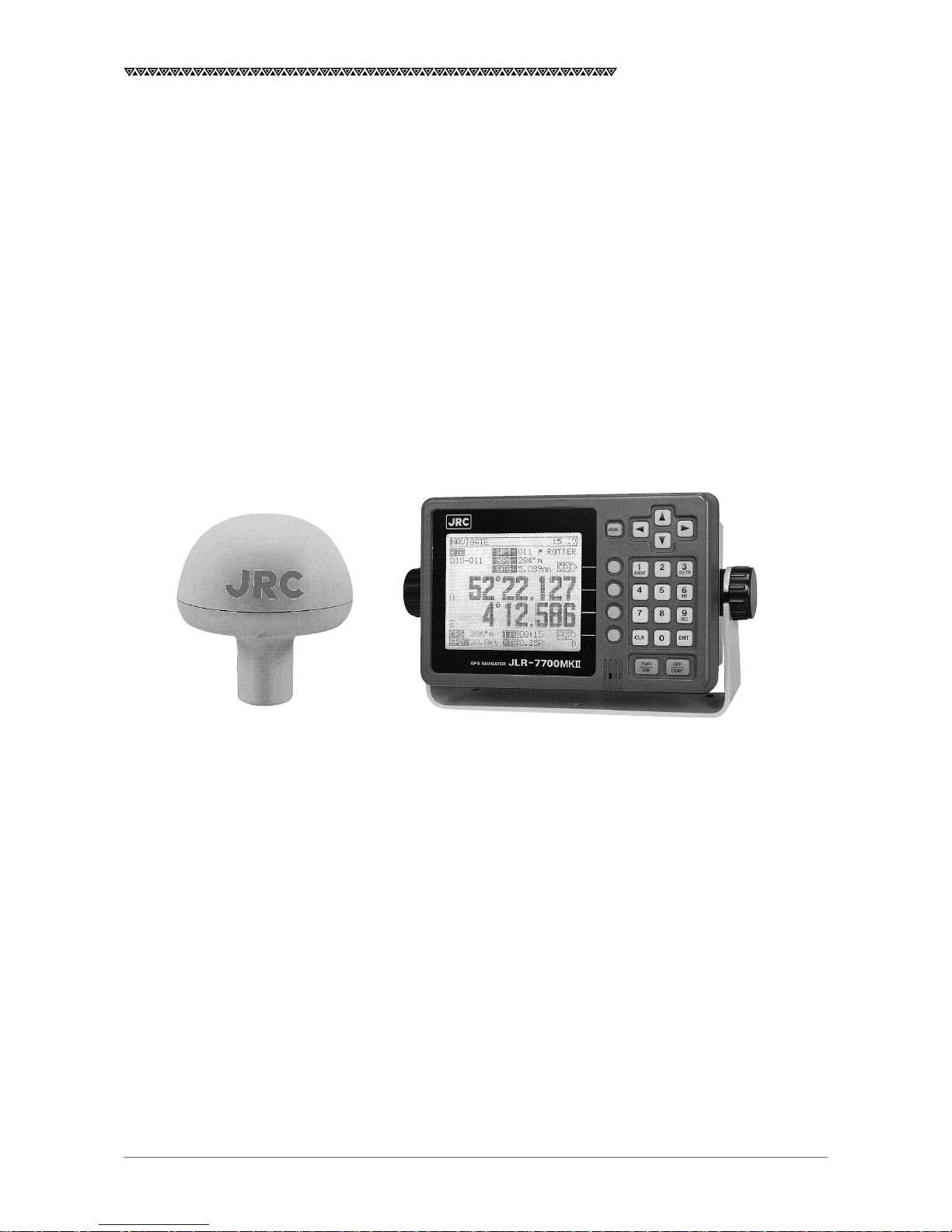
JLR-7700 MK2GPS Navigator
4. Operation Method ....................................................................................................... 39
4.1 Basic Operations ...........................................................................................................................39
4.1.1 Turning the Power ON and OFF ..............................................................................................39
4.1.2 Selection of the Language .......................................................................................................39
4.1.3 Contrast Adjustment ................................................................................................................39
4.1.4 Backlight Adjustment ...............................................................................................................40
4.1.5 Return to the SELECT MODE Screen.....................................................................................40
4.2 Screens ..........................................................................................................................................40
4.2.1 Display and Operation List for the NWZ-4570B Navigator ......................................................41
4.3 How to use the Navigation Information Screens ............................................................................ 42
4.3.1 NAVIGATE Screen ...................................................................................................................42
4.3.1.1 Setting a Destination .........................................................................................................43
4.3.1.2 To Change the Leg (Manual Leg Change) ........................................................................ 45
4.3.1.3 To Skip (Omit) a Destination .............................................................................................. 45
4.3.1.4 Canceling the Route ..........................................................................................................46
4.3.1.5 Storing the Current Position (Event) ..................................................................................46
4.3.2 COURSE DEVIATION IND. Screen .........................................................................................47
4.3.2.1 Switching the CDI Meter Scale .......................................................................................... 47
4.3.2.2 Switching the Display on the Two Bottom Lines ................................................................47
4.3.3 NAVIGATE AUX Screen ...........................................................................................................49
4.3.3.1 Magnetic Compass Correction .......................................................................................... 49
4.3.3.2 Setting the Display Unit .....................................................................................................50
4.3.3.3 Selection of the Data Output Format .................................................................................50
4.4 PLOT Screen (Tracked Line Screen) .............................................................................................51
4.4.1 PLOT Screen ...........................................................................................................................51
4.4.1.1 Setting the Horizontal Scale Range...................................................................................51
4.4.1.2 Setting the Plot Interval .....................................................................................................51
4.4.1.3 Erasing the Tracked Line ...................................................................................................52
4.4.1.4 Setting a Destination .........................................................................................................52
4.4.1.5 To Store the Current Position ............................................................................................. 52
4.4.1.6 Turning ON and OFF the Display for the Two Bottom Lines .............................................. 52
4.4.1.7 To Display the Current Position at the Center of the Screen .............................................52
4.4.2 PLOT AUX Screen ...................................................................................................................53
4.4.2.1 Setting the Geodetic System .............................................................................................53
4.4.2.2 Entering the Correction Values for Latitude and Longitude ............................................... 53
4.4.2.3 Setting the DGPS BEACON ..............................................................................................54
4.5 Registration the Waypoint ..............................................................................................................55
4.5.1 WAYPOINT Screen ..................................................................................................................55
4.5.2 WAYPOINT LIST Screen .........................................................................................................57
4.5.2.1 Copying the Waypoint Data ............................................................................................... 57
4.5.2.2 Erasing the Waypoint Data ................................................................................................57
4.5.3 ROUTE SEQUENCE Screen ................................................................................................... 58
4.5.3.1 Setting the Route Plan ....................................................................................................... 58
4.5.3.2 Canceling the Route Plan ..................................................................................................58
4.5.3.3 Setting the Arrival Alarm Range ........................................................................................59
4.5.3.4 Switching between the Automatic and Manual Leg Change .............................................59
4.5.3.5 Switching between Great-circle and Rhumb-line ............................................................... 60