Jrco 753 User manual

MODEL 753 Operator’s Manual
20195 South Diamond Lake Road, STE 100
Rogers, MN 55374
800.966.8442
1
Operator’s Manual
7918-3.JRC
WARNING
READ AND UNDERSTAND THE OPERATOR’S MANUAL COMPLETELY BEFORE USING
THIS ATTACHMENT. ASSEMBLE, TEST AND USE ONLY IN ACCORDANCE WITH THE
OPERATOR’S MANUAL INSTRUCTIONS.

MODEL 753 Operator’s Manual
20195 South Diamond Lake Road, STE 100
Rogers, MN 55374
800.966.8442
2
Table of Contents
1 Introduction................................................................................................................................................4
1.1 ....Application............................................................................................................................................................4
1.2 ....Navigating This Manual .................................................................................................................................4
1.3....Operation References/Terminology..........................................................................................................4
1.4 ....Owner Assistance ...............................................................................................................................................5
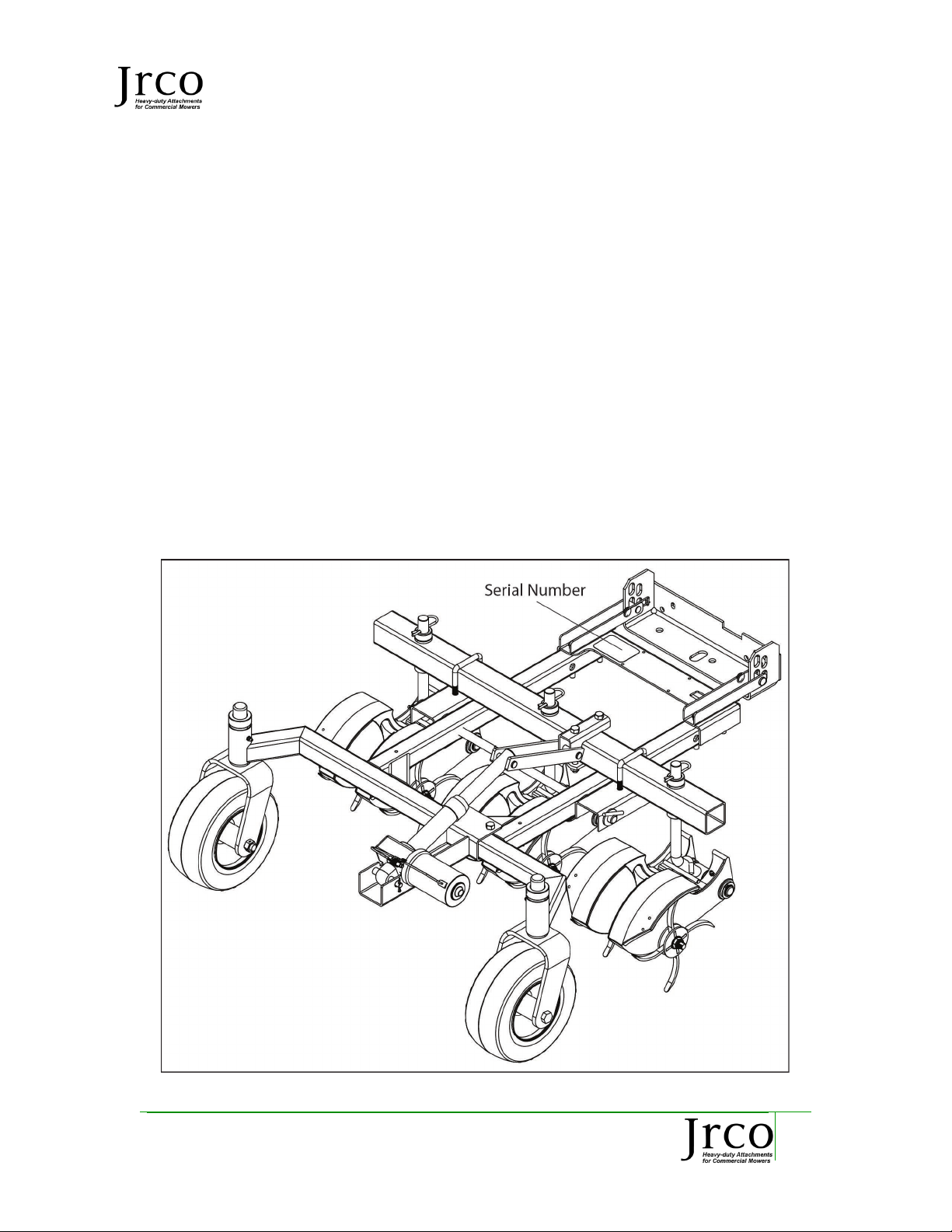
1.5 ....Model Identification .........................................................................................................................................5
1.6 ....Further Assistance.............................................................................................................................................6
2 Assembly and Set-up ...............................................................................................................................7
2.1 ....Frame Assembly Parts .....................................................................................................................................7
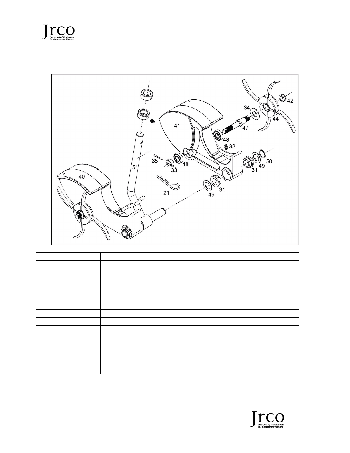
2.2 ....Caster Head Assembly Parts .........................................................................................................................9
2.3 ....Tools Required..................................................................................................................................................10
2.4 ....Power Unit Requirements...........................................................................................................................10
2.5 ....Unpacking Your Attachment.....................................................................................................................10
2.6 ....Torque Requirements ...................................................................................................................................10
2.7 ....General Assembly............................................................................................................................................10
2.8 ....Stabilizer Frame to Tow Tongues Assembly ......................................................................................11
2.9 ....Pivot Arms to Actuator Mount to Extension Harness Assembly................................................11
2.10..Wheels to Yokes Assembly ..........................................................................................................................11
2.11..Caster Bar to Top Pivot Assembly ...........................................................................................................12
2.12..Connecting Actuator .....................................................................................................................................12
2.13..Aerator Heads Assembly..............................................................................................................................12
2.14..Mount Hitch to Tow Vehicle.......................................................................................................................13
2.15..Connecting Power Wire to Vehicle Battery ........................................................................................13
2.16..Aerator to Hitch...............................................................................................................................................13
2.17..Battery Harness to Switch ..........................................................................................................................13
3 Operation Instructions ........................................................................................................................ 14
3.1 ....Before Operation.............................................................................................................................................14
3.2 ....Operator Safety................................................................................................................................................14
3.3 ....Operation............................................................................................................................................................15

MODEL 753 Operator’s Manual
20195 South Diamond Lake Road, STE 100
Rogers, MN 55374
800.966.8442
3
4 Attachment Instructions..................................................................................................................... 16
5 Mounting Instructions ......................................................................................................................... 16
6 Dismounting Instructions................................................................................................................... 16
6.1 ....Removing Hooker Aerator..........................................................................................................................16
7 Storage Instructions ............................................................................................................................. 16
7.1 ....Storing Your Hooker Aerator....................................................................................................................16
8 Transporting Instructions.................................................................................................................. 17
8.1 ....Transporting Your Hooker Aerator .......................................................................................................17
9 Field Use Set-up and Instructions................................................................................................... 17
9.1 ....Field Preparation Hooker Aerator..........................................................................................................17
10 Maintenance Instructions................................................................................................................... 18
10.1..General.................................................................................................................................................................18
10.2..Daily Maintenance .........................................................................................................................................18
10.3..Seasonal Maintenance..................................................................................................................................18
11 Specifications........................................................................................................................................... 19
12 Warranty ................................................................................................................................................... 20

MODEL 753 Operator’s Manual
20195 South Diamond Lake Road, STE 100
Rogers, MN 55374
800.966.8442
4
1Introduction
JRCO takes pride in its attachments and have designed and engineered quality, commercial
built attachments designed to help you efficiently and effectively be more productive at tasks.
1.1 Application
The JRCO Hooker Aerator, used for years as a front-mounted attachment for landscape
aeration, is now available in a 38”, three head tow-behind version.
The soft-plug style aeration is ideal for golf fairways, sports fields or anywhere true plug
aeration is needed, without the messy compacted core clean-up of a hollow tine aerator.
The JRCO Hooker Aerator is many times faster than traditional hollow tine aerators, and is
low maintenance with few moving parts and no engine.
The tines pierce deep into the soil, hooking and lifting loose plugs of dirt that disperse on
the surface, spreading nutrients over the surface. The turf can be played immediately after
aeration. Some operators choose to pull a drag over the surface one to three hours after
aeration to smooth the aerated surface. Use it in combination with over-seeding for
renovating distressed or diseased turf. Holes are approximately ½” wide by 1-1/4” long and
up to 3” deep. Soil volume removed is comparable with a 5/8” hollow tine core.
The Hooker tow-behind aerator comes complete with a two-point hitch, rigid frame and
swiveling caster wheels that allow the aerator to track directly behind the tow vehicle and
prevents jackknifing when backing up. The aerator caster heads swivel, allowing them to
turn while aerating. The six floating rotor heads lift independently over rocks and other
obstacles, while the other heads continue to aerate. An electric actuator lifts the heads into
the transport position.
1.2 Navigating This Manual
1. Use this manual to help familiarize yourself with safety, assembly, operation,
adjustments, troubleshooting, maintenance, specifications and warranty
information. It is very important that you read this manual and follow the
instructions to ensure safe operation of the attachment.
2. Please visit www.jrcoinc.com for updated information.
1.3 Operation References/Terminology
References throughout this manual referred to as “Right” or “Left” are determined by being
seated face-forward on Mower and facing the direction the unit will operate while in use.

MODEL 753 Operator’s Manual
20195 South Diamond Lake Road, STE 100
Rogers, MN 55374
800.966.8442
5
1.4 Owner Assistance
Please complete the Warranty/Product Registration at the time of purchase. You will need
to fill out a new warranty card for your new unit and send it in, or you may visit our website
www.jrcoinc.com and complete our online registration form. We require this information
so we can keep you update to date with any important information about your attachment
and provide you with the best customer service possible.
The parts and components used on your JRCO Attachment have been specifically
engineered for JRCO Attachments and should only be replaced with JRCO parts. Contact
your local JRCO Dealer for replacement parts or contact our customer service department
for assistance in parts, locating your local servicing dealer and more. Your local dealer is
equipped and trained to handle service and repair for your attachment.
1.5 Model Identification
Please fill in your model and serial number below for future reference. This will help assist
in prompt service when ordering parts and service for your local JRCO Dealer.
Model No.___________753_______________________ Serial No. ________________________________________
Refer to the image below for location of your serial number plate:

MODEL 753 Operator’s Manual
20195 South Diamond Lake Road, STE 100
Rogers, MN 55374
800.966.8442
6
1.6 Further Assistance
Your dealer and all of us at JRCO want you to be pleased with your attachment. Should you
require further assistance or have questions regarding your attachment, please contact your
local dealer where you purchased your attachment. If you are unable to satisfy your needs
by your local dealer, please contact us at:
JRCO
20195 South Diamond Lake Road, STE 100
Rogers, MN 55374
800-966-8442
info@jrcoinc.com
www.jrcoinc.com

MODEL 753 Operator’s Manual
20195 South Diamond Lake Road, STE 100
Rogers, MN 55374
800.966.8442
7
2Assembly and Set-up
2.1 Frame Assembly Parts

MODEL 753 Operator’s Manual
20195 South Diamond Lake Road, STE 100
Rogers, MN 55374
800.966.8442
8
Ref
Part No.
Description
Qty
Ref
Part No.
Description
Qty
1
5026.JRC
Box Hitch
1
23
8093.JRC
HH Bolt, ½ x 5 ½”
2
2
7805-2.JRC
Stabilizer Frame
1
24
4233.JRC
2-way locknut, ½-13
2
3
8281.JRC
Frame Assembly
1
25
7915.JRC
Shaft Collar, 1”
2
4
7883.JRC
Tow Tongue
2
26
7583-1.JRC
Flange Bushing, 1”
4
5
7803-1.JRC
Pivot Arm
2
27
7281.JRC
Set Screw, 5/16-18 x
5
6
4003.JRC
Clevis Pin, ½ x 1 ¼”
2
28
7845.JRC
Clevis Pin 3/8 x2”
2
7
4009.JRC
Safety Clip
2
29
7251.JRC
Cotter Pin, 1/8 x 1 ½
1
8
7278.JRC
HH Bolt, 3/8 x 2 ½”
6
30
3047.JRC
Washer, 5/8” SAE
4
9
4236.JRC
2-way locknut, 3/8-16
10
31
7873.JRC
Flange Bushing, ¾”
18
10
7806-1.JRC
Pivot Rod
1
32
7816.JRC
Grease Fitting
8
11
7842-3.JRC
Aerator Head Assembly
3
33
7949.JRC
Extension Harness
1
12
7809-2.JRC
Actuator Mount
1
34
7851.JRC
Switch Harness
1
13
7833.JRC
Actuator
1
35
7430-4.JRC
Battery Harness
1
14
7914.JRC
Yoke
2
Fuse AGC-20
1
15
7867.JRC
Wheel, 9 x 3.5 x 4
2
36
7846.JRC
Cotter pin 1/8 x ¾”
3
16
7844-1.JRC
Caster bar Assembly
1
37
7243.JRC
Cable Tie, 11”
8
17
7808.JRC
Top Pivot
1
38
4671-3.JRC
Clamp Bar 3.3”
1
18
7308.JRC
HH Bolt, 3/8 x 3 ½”
2
39
8299.JRC
Reducer bushing
2
19
4684.JRC
Clevis Pin, 3/8 x 2 ¾”
1
52
7947-1.JRC
Actuator Link
2
20
7811.JRC
U-bolt, 3/8-16 x 2 x 2 ¾”
2
53
8261.JRC
Switch Bracket
1
21
3045.JRC
Hairpin cotter
3
54
4235.JRC
3/8” SAE washer
2
22
7828.JRC
Shaft Collar, ¾”
6
7859.JRC
Velcro Tie
2

MODEL 753 Operator’s Manual
20195 South Diamond Lake Road, STE 100
Rogers, MN 55374
800.966.8442
9
2.2 Caster Head Assembly Parts
Ref
Part No.
Description
Qty/Unit
Qty/Head
31
7873.JRC
Flange bushing, ¾”
18
4
32
7816.JRC
Grease fitting
8
2
33
8288.JRC
Castle Nut, ½-20
6
2
34
3047.JRC
SAE Flatwasher, 5/8”
6
2
35
7846.JRC
Cotter Pin, 1/8 x ¾”
6
2
40
7904R.JRC
Casting, Right
3
1
41
7904L.JRC
Casting, Left
3
1
42
7908.JRC
Nylon Locknut, ½-20
6
4
44
7860.JRC
Tine Rotor
6
2
47
8267.JRC
Axle
6
2
48
8270.JRC
Bearing, 1 1/8 x 5/16 x ½”
12
4
49
7819.JRC
Machine Bushing, ¾”
12
4
50
7942.JRC
Snap Ring, ¾” External
6
2
51
7823-1.JRC
Caster Pin
3
1

MODEL 753 Operator’s Manual
20195 South Diamond Lake Road, STE 100
Rogers, MN 55374
800.966.8442
10
2.3 Tools Required
•Socket Wrench: 9/16” & ¾”
•Open or Box Wrench: 9/16” & ¾”
•Pliers
•Allen Wrench: 5/32”
•Grease gun
2.4 Power Unit Requirements
The Hooker Soft-Plug Aerator is designed to be attached to the JRCO hitch for mounting on zero
turn mowers, UTVs and lawn tractors.
2.5 Unpacking Your Attachment
Your Hooker Aerator will ship in 2 boxes. Carefully set the boxes on a flat working area. Carefully
unbox the attachment and verify that all fasteners and components are included.
2.6 Torque Requirements
Please reference the Torque Chart below for correct values when assembling your attachment.
3/8”
HH Bolts and Nuts
30 ft.-lbs.
¼”
HH Bolts and Nuts
8 ft.-lbs.
2.7 General Assembly
This attachment is shipped partially assembled. If purchased from a JRCO Dealer, the dealership
may assist in assembly of attachment. Review all safety and assembly instructions in this manual
before assembly.
CAUTION
Sharp edges
Heavy

MODEL 753 Operator’s Manual
20195 South Diamond Lake Road, STE 100
Rogers, MN 55374
800.966.8442
11
2.8 Stabilizer Frame to Tow Tongues Assembly
Refer to Figure 1-1
1. Align holes in stabilizer frame, tow tongue and
aerator frame.
2. Secure with four 3/8-16 x 2 ½” hex bolts and two-
way locknuts.
2.9 Pivot Arms to Actuator Mount to Extension
Harness Assembly
Refer to Figure 1-2
1. Insert pivot rod through two pivot arms and aerator
frame using 5/8” SAE flatwashers on each side of Figure 1-1
the pivot arms. Secure with cotter pin.
2. Slide actuator mount onto the aerator frame and
align the right mount hole with the triangular hole
at the right of the frame. Secure with two 3/8-16 x 2
½” hex head bolts and 3/8 two-way locknuts.
3. Attach the extension harness to the underside of the
frame. Put the cord through the rectangular hole in
the stabilizer frame and route the cable along the
underside of the right hand frame leg. Secure with
cable ties. Figure 1-2
2.10 Wheels to Yokes Assembly
Refer to Figure 1-6
1. Use ½-13 x 5 ½” hex head bolt and ½-13 two-way
locknut to install wheel in each yoke.
NOTE: do not over tighten. Wheel should spin freely in yoke.
2. Slide yoke through flange bushings in aerator frame
and secure with 1” shaft collar.
3. Fill spindle housing with all-purpose grease
Figure 1-3

MODEL 753 Operator’s Manual
20195 South Diamond Lake Road, STE 100
Rogers, MN 55374
800.966.8442
12
2.11 Caster Bar to Top Pivot Assembly
Refer to Figure 1-4
1. Center the caster bar over aerator frame and pivot
arms. Use two 3/8-16 x 2 ¾” square u-bolts and 3/8-
16 two-way locknuts to install caster bar.
2. Attach actuator top pivot to caster bar using two 3/8-
16 x 3 ½” hex head bolts, a 3.3” clamp bar and 3/8”
two-way locknuts as show in figure 1-4. Do not
tighten at this time, it will be tightened when aligned
with the actuator.
Figure 1-4
2.12 Connecting Actuator
Refer to Figure 1-5
1. Fully extend the actuator. Place actuator into
actuator mount with the motor to the right as
shown. Insert a 3/8 x 2 ¾” clevis pin through the
reducer bushings and the actuator and secure with
a 1/8 x 3/4” cotter pin.
2. Install two actuator link plates between the actuator
and top pivot. Attach with 3/8 x 2” clevis pins and
cotters. Center the top pivot and tighten. Connect
power wire from the extension harness to actuator
plug. Figure 1-5
2.13 Aerator Heads Assembly
Refer to Figure 1-6
1. Retract the actuator and pivot the bar into the
transport position. Slide each aerator head assembly
into the aerator bar, place a ¾” shaft collar over the
stem and secure with a hairpin cotter. Adjust the
lower shaft collar to the bottom of the caster bar and
tighten the set screw.
Figure 1-6

MODEL 753 Operator’s Manual
20195 South Diamond Lake Road, STE 100
Rogers, MN 55374
800.966.8442
13
2.14 Mount Hitch to Tow Vehicle
NOTE: Park mower/UTV close to clevis area.
1. Position hitch so clevis pin slots are approximately
11 ½” from ground and slots are vertical.
2. Drill holes in hitch and attach hitch to vehicle
framework or drawbar using 5/16” bolts.
2.15 Connecting Power Wire to Vehicle Battery
1. Connect supplied battery wire directly to battery
terminals. Route battery cable, back to hitch, along
vehicle frame. Safely away from pinch points and
rotating parts, and secure with cable ties.
2.16 Aerator to Hitch
1. Align the tow tongues with the slots in the hitch.
Choose the slots that will keep the aerator level.
Attach with clevis pins and safety clips.
2.17 Battery Harness to Switch
Plug the battery harness and power wire into the switch
harness. Route the switch harness up to the vehicle
operator. Figure 1-7
Secure with cable ties and hook and loop ties.
Figure 1-9

MODEL 753 Operator’s Manual
20195 South Diamond Lake Road, STE 100
Rogers, MN 55374
800.966.8442
14
3Operation Instructions
3.1 Before Operation
Safety, hazard and accident prevention is essential. You must use awareness, concern, and proper
training when operating and utilizing this attachment. You must NOT use this attachment without
reading and understanding the Operator’s Manual. Make sure the operator has completed and
understands the contents of this manual before operation. Refer to the chart below for key areas
and ensure they are understood:
3.2 Operator Safety
CAUTION
•Know the Aerator’s controls and how to stop quickly. READ THE
OWNER’S MANUAL.
•Shut off the engine before attaching, adjusting or disconnecting the
Hooker Aerator.
•Reduce speed on uneven ground.
•DO NOT operate the Hooker Aerator on concrete or asphalt surfaces.
•DO NOT ride or stand on aerator.
•Keep all bolts and nuts tightened.
•Check and replace broken parts before operating the mower and
aerator.
•Watch mower speeds. Do not operate the Hooker Aerator at a speed that
is too fast for maintain safe control. Do not go too fast for conditions.
•Do not operate the Hooker Aerator on slopes steeper than 30 degrees.
•Be careful when lowering the aerator to the ground. Keep feet clear of
the tines when lowering the cater heads.
•Wear safety glasses for protection against flying dirt and debris.
•DO NOT allow others, including children and pets, in the area while
operating the Hooker Aerator
•For added Hooker Aerator stability and to prevent loss of control of
when using Hooker Aerator: Aerate up and down the face of slopes –
never across the face of any slope. Do drive at reduced speeds on uneven
ground and when turning corners.

MODEL 753 Operator’s Manual
20195 South Diamond Lake Road, STE 100
Rogers, MN 55374
800.966.8442
15
3.3 Operation
Now you should have read your Operator’s Manual and properly attached your Hooker Aerator.
Using the Hooker Aerator is simple, but there are things you need to consider before use. If you are
using the attachment in an area that has large stumps, rocks, debris, exposed electrical or gas lines
or foreign material that could cause damage to the attachment should be marked. You will want to
avoid any sizable objects to avoid damage or injury. Mark location of irrigation sprinkler heads or
control boxes and avoid.
Now that you know where you are going to use your Hooker Aerator and have taken the necessary
precautions surveying the area, you are ready to begin use. Begin by ensuring your attachment is in
field ready position.
1. To operate the aerator, lower the caster heads to the ground while moving forward. As you
move forward, the caster heads will move into the aeration position.
NOTE: Ensure that the actuator is in the fully extended position and the caster bar is resting fully on
the support frame. Failure to do this may result in the caster pins not being in the correct, vertical
position and maneuverability will suffer. When the caster heads are not fully down, they can turn
sideways on uneven terrain, which will put side loads on the tines.
2. The caster heads will swivel and track with the turning of the tow vehicle. The heads must
be raised before backing up.
3. Straighten the track of the aerator
heads some-what before lifting the
caster bar to the transport position. If
the heads are lifted while they are
turned, it will put extra load on the
lifting actuator and may result in a
blown fuse.
4. Lower the heads to the floor when
trailering, to take the load off the
actuator.
Figure 1-10
DANGER
DO NOT work over any area that has exposed electrical wiring or gas lines.
Making contact with electrical wiring or gas lines/pipes can cause serious
injury or death.

MODEL 753 Operator’s Manual
20195 South Diamond Lake Road, STE 100
Rogers, MN 55374
800.966.8442
16
4Attachment Instructions
1. Use the Hooker Aerator for its intended purposes only. Never use it to carry, push, pull or
drag any object other than its intended purpose.
2. Misuse can lead to damage of the attachment.
3. Do not exceed speeds of 8 mph.
4. Mark and avoid obstacles including sprinkler heads.
5Mounting Instructions
6Dismounting Instructions
6.1 Removing Hooker Aerator
To remove Hooker Aerator, follow these steps:
1. Park Hooker Aerator and Mower on a solid level surface. Engage parking brake and shut
engine off and remove key.
2. Ensure feet are clear from beneath the attachment. Remove clevis pins and detach battery
plug. With a strong grip, lower attachment to ground.
3. Replace clevis pins to avoid lost or misplaced pins.
4. Be sure attachment is clear of Mower before moving power unit away from attachment.
7Storage Instructions
7.1 Storing Your Hooker Aerator
Ensure your attachment is clear of debris, inspect for damage or repairs needed and service as
necessary before storage. This will ensure the attachment is ready for use the next time it’s in the
field and ensure repairs are not accidentally forgotten or overlooked.
1. Carefully clear all dirt, grease and debris that may be on your Hooker Aerator.
DANGER
A Crush Hazard exists when mounting attachment to mount bar. Do Not
allow anyone to stand between tractor and attachment while mounting.
Always make sure the clevis pins are secure before operation.
Always make sure the parking brake is engaged on mower/UTV, engine is
turned OFF and key is removed before mounting the attachment.

MODEL 753 Operator’s Manual
20195 South Diamond Lake Road, STE 100
Rogers, MN 55374
800.966.8442
17
2. When finished cleaning dirt and debris, wash the surfaces thoroughly with a garden hose.
3. Repaint parts where paint is worn or chipped to prevent rust from forming. A coting of oil
may also be applied to minimize oxidation.
4. Replaced all damaged or missing decals.
5. Store Hooker Aerators indoors if possible. Inside storage will reduce maintenance and
extend life of attachment.
6. Inspect for loose or worn parts and adjust or replace as needed.
8Transporting Instructions
8.1 Transporting Your Hooker Aerator
Transporting with aerator
1. Lower the caster heads to the floor when trailering the aerator to take the weight off the
actuator.
2. Secure aerator to trailer with strap
9Field Use Set-up and Instructions
The following procedures should be carried out by the operator. Other persons should be
cleared of the area.
9.1 Field Preparation Hooker Aerator
1. Ensure your Hooker Aerator is level front to back.
2. Only aerate with the caster bar lowered fully to frame. Do not aerate with heads lowered
part way.
DANGER
Failure to secure aerator can cause equipment damage or personal injury

MODEL 753 Operator’s Manual
20195 South Diamond Lake Road, STE 100
Rogers, MN 55374
800.966.8442
18
10 Maintenance Instructions
10.1 General
Proper servicing and adjustment is key to extending the life of your attachment. Carefully insect
and routinely maintenance to avoid costly downtime and repairs.
Check all bolts and nuts after using for several hours to ensure they are secure. Replace any worn,
damaged or missing safety labels.
The parts on your JRCO Hooker Aerator have been designed specifically for your attachment and
should be replaced with genuine parts from your local JRCO Dealer. Do not alter the equipment in
any way.
10.2 Daily Maintenance
Clean, inspect, service and repair any necessary parts that are
necessary. This will ensure it is ready for use the next time
mounted.
1. Check tines for wear and bearings for looseness. Replace
tine rotors if the tines have worn to less than 2 ½” long.
2. Add grease to each of the fittings at the front of each
casting, wheel spindle and wheel
3. The tines should be cleaned immediately after operation.
10.3 Seasonal Maintenance
1. Spray caster pins and flange bushings with silicone
lubricant.
2. Replace the battery harness fuse with an AGC-20 or
equivalent only.
Figure 1-11

MODEL 753 Operator’s Manual
20195 South Diamond Lake Road, STE 100
Rogers, MN 55374
800.966.8442
19
11 Specifications
Model 753 Hooker Soft-Plug Aerator
Approximate Shipping Weight
198 lbs.
Aeration Width
38”
Aeration Pattern
5” x 6”
Hole Size
½” wide x 1.25” long, up to 3” dep
Tines
3/8” wide x 3” long hardened high carbon
alloy steel
Productivity
1.5 acres per hour @ 5 mph (66,000 sq. ft.
per hour)
Dimensions
38.25” x 35” x 16”

MODEL 753 Operator’s Manual
20195 South Diamond Lake Road, STE 100
Rogers, MN 55374
800.966.8442
20
12 Warranty
Table of contents