JTX Fitness Cyclo 5 User manual

JTX Cyclo 5
User Guide

1. Introduction & Safety
2. Safety & Maintenance Summary
3. Exploded Assembly Diagram
4. Main Parts List
5. Assembly
6. Operation
7. Training Notes
CONTENTS

INTRODUCTION &
SAFETY
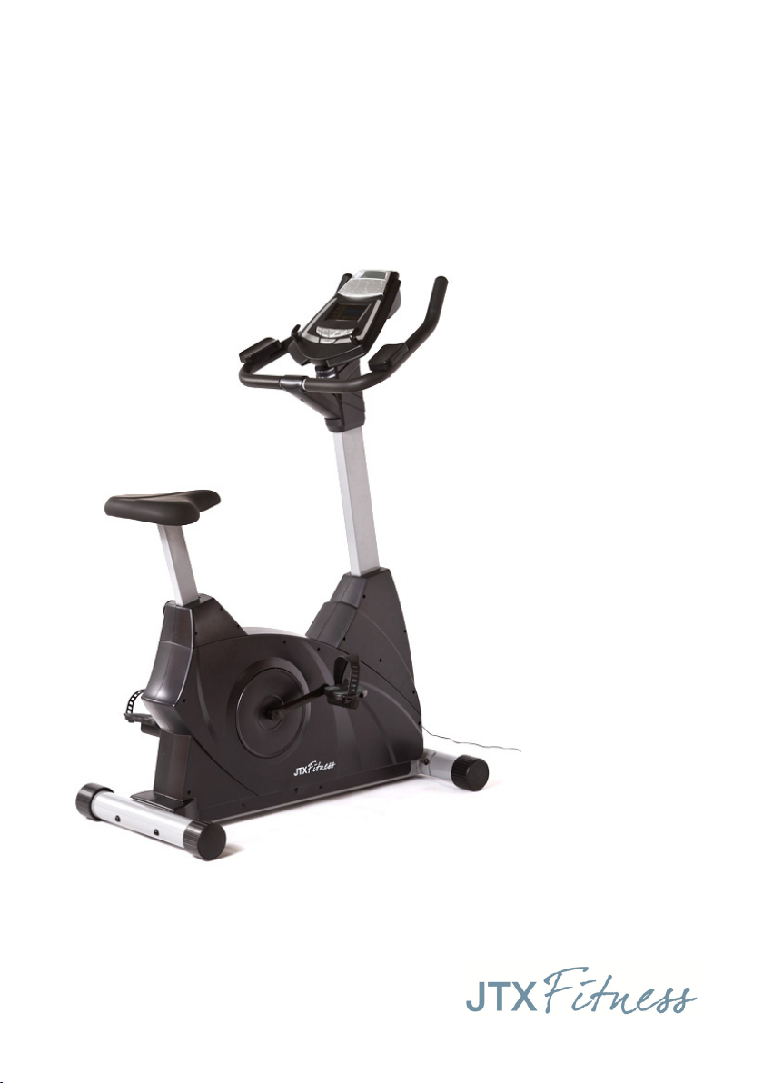
Thank you for purchasing the JTX Cyclo 5.
Please read the following precautions before exercising. The follow-
ing assembly guide should help with assembly. If you have any issues
with assembly, motivation or exercise inspiration please call jtx tness
and our personal trainers will be available to help. Enjoy your bike.
SAFETY WARNING
BEFORE ANY NEW EXERCISE YOU SHOULD ALWAYS CONSULT A
DOCTOR. IF YOU HAVE ANY KNOWN MEDICAL CONDITIONS, OR ANY
PHYSICAL LIMITATION ON YOUR ABILITY TO EXERCISE IT IS STRONGLY
RECOMMENDED THAT YOU CONSULT A DOCTOR IN ORDER TO AVOID
POSSIBLE INJURY. IF, AT ANY TIME WHILE USING A JTX FITNESS EXER-
CISE BIKE YOU EXPERIENCE ANY DIZZINESS, FAINTNESS, SHORTNESS
OF BREATH, OR OTHER PAIN YOU SHOULD STOP YOUR WORKOUT
IMMEDIATELY AND CONSULT A DOCTOR. FAILURE TO DO SO COULD
RESULT IN PERSONAL INJURY.
Set Up
This machine should be set up on a hard level service in an area free
from obstructions.
This exercise bike should not be used outdoors, near a pool or any
source of water, extreme humidity or damp. Contact with water could
cause a short circuit, which could cause injury or damage to the bike.
Unplug the machine when not in use.
Never move the machine while in use.

SAFETY & MAINTENANCE
SUMMARY
1. Tighten all bolts on a regular basis.
2. Keep children and pets away from this machine at all times. Do not
leave unattended children in the same room with this machine.
3. If the user experiences dizziness, nausea, chest pain or any other
abnormal symptoms, stop the workout at once and consult a Doctor.
4. Position the Cyclo 5 on a clear, level surface. Do not store near
water or outdoors.
5. Do not place any sharp objects around the bike.
6. If the bike is not functioning correctly please contact JTX tness
immediately. Do not use the bike if faulty.

EXPLODED DIAGRAM

1. MAIN FRAME
2. FRONT STABILISER
3. REAR STABILISER
7. TRANSPORT ROLLER CAPS
8. REAR STABILISER END CAPS
9L/R PEDALS LEFT & RIGHT
10. SEAT POST
11. SADDLE
16. SEAT ADJUSTOR
17. HANDLEBAR POST
18L/R FRONT COLLAR
22. CONSOLE
23. ELBOW PADS
30. HANDLEBAR
31. EXTENSION WIRE
32. SENSOR WIRE
33. PEDAL CRANKS (L/R)
35. HANDLEBAR COVER (L/R)
36a/b. HANDLEBAR COVER (Upper/Lower)
37. POWER ADAPTER
MAIN PARTS LIST

Step 1
First attach the stabilisers (2, 3)
to the main frame (1). Please
note the front stabiliser has the
bolts washers and nuts screwed
into it. The bolts for the back
stabiliser are in the tool kit.
Step 2
The nuts to attach the saddle
(11) to the saddle post (10) are
screwed onto the saddle. Re-
move the nuts and use them to
attach the saddle to the saddle
post.
Then remove the seat adjuster
(16), insert the saddle post to
the main frame (1) and use
the seat adjustor to adjust the
saddle to the required height.
It is recommended that all parts are removed from the box before
commencing assembly. It is also recommended that two people as-
semble the JTX Cyclo 5.
ASSEMBLY

Step 3
The pedals (9L/9R) and pedal straps are labelled right and left. The
pedals screw directly into the cranks (33L/R) on either side of the bike.
Please note to attach the right hand pedal you should turn the nut
clockwise. To attach the left hand pedal the nut should be turned
anti-clockwise.
Step 4
To attach the handlebar post (17), the front
collar (18L/R) needs to be removed. To do
this use the long handled cross head screw-
driver to remove the 5 screws that hold the
collar in place. Once the screws have been
removed each side will slide o.
ASSEMBLY

Step 5
Remove the two screws from the front
of the handle bar post and the three
screws and nuts which run through the
centre of the post.
Attach the cables a the bottom of the
handlebar support post (17) to the
cables in the main frame (1) before in-
serting the post into the frame.
Once inserted re-attach all 5 screws to
hold the post in place.
Step 6
Slide the collar back into position. Secure
in place using the screws which were previ-
ously removed.
ASSEMBLY

Step 7
Thread the cables from the
handlebar up through the
hole in the front of the post
(17) and temporarily secure in
place using the elastic band at
the top of the post.
Then secure the handlebar
(30) to the post (17) using the
nuts and bolts provided.
Then attach the elbow pads
(23) to the handlebar (30) with
the screws (24).
Step 8
Remove the cross head tapping
screws from the upper and lower part
of the handle. Then rst attach the
lower handlebar cover (36a) then at-
tach the upper handlebar cover (36b)
using those self tapping screws.
ASSEMBLY

Step 9
Remove the screws from the
back of the console (22) be-
fore connecting the cables
at the top of the handlebar
support post (17) to the
cables on the back of the
console.
Be sure to feed the cables
back into the post to avoid
them being caught before
securing the console using
the 4 screws which were
previously removed.
Step 10
Finally remove the three screws from the
handlebar cover (35). Then place the handle-
bar covers on either side of the handlebar
post (17) beneath the console (22). Secure in
place using the 3 screws.
You are now ready for you rst workout!
ASSEMBLY

CONSOLE BUTTONS
START/STOP
Use this button to start or stop the program chosen. Hold for 2 sec-
onds to reset the computer.
ENTER
Use this button to select from PROGRAMS, GENDER, TIME, HEIGHT,
WEIGHT, DISTANCE, WATT, TARGET HEART RATE and AGE.
MODE
Use this button to change the data on display. Pressing the mode but-
ton allows you to switch between viewing the RPM/SPEED and CAL /
WAT T.
UP
Use this button to increase the values of PROGRAMS, GENDER, TIME,
HEIGHT, WEIGHT, DISTANCE, WATT, TARGET HEART RATE and AGE.
DOWN
Use this button to decrease the values of PROGRAMS, GENDER, TIME,
HEIGHT, WEIGHT, DISTANCE, WATT, TARGET HEART RATE and AGE.
RECOVERY
Use this button to start the pulse recovery test.
CONSOLE

The JTX Cyclo 5 has 16 programs. Every program will be displayed
by a graph which consists of 10 columns. Each column is 8 blocks tall
with each block representing 2 resistance levels.
When the time is counting upwards, each column will represent 3
minutes. When the time is counting downwards, each column will
represent the total time set divided by the 10 columns. So for ex-
ample if you have set a program for 40 minutes, each column will be
4 minutes.
The 16 programs include manual and automatic options, BMI test,
heart rate control and custom user programs:
Program 1 - Manual Program
Program 2 - Rolling Hills Program
PROGRAMS

Program 3 - Valley Program
Program 4 - Fat Burn Program
Program 5 - Climb and Descent Program
Program 6 - Mountain Climb Progam
PROGRAMS

Program 7 - Interval Program
Program 8 - BMI Program
Program 9 - Target Heart Rate Program
Program 10 - 60% Heart Rate Program
PROGRAMS

Program 11 - 75% Heart Rate Program
Program 12 - 85% Heart Rate Program
Program 13 - User 1
Program 14 - User 2
PROGRAMS

Program 15 - User 3
Program 16 - User 4
PROGRAMS

Manual Program
Program 1 allows you to manually adjust all the parameters for your
workout.
• PresstheENTERbuttontoselectTIME,DISTANCEandAGE.Use
the UP or DOWN buttons to adjust any of these values. The default
level of resistance is 6.
• PressSTART/STOPtobeginyourexercise.
• Duringyourexerciseyoucancontinuetomakeadjustments
to the resistance using the UP and DOWN buttons.
Automatic Programs
Programs 2 to 7 are preset with an automatic training routine.
• PresstheENTERbuttontoselectTIME,DISTANCEandAGE.Use
the UP or DOWN buttons to adjust any of these values.
• PressSTART/STOPtobeginyourexercise.
• Duringyourexerciseyoucancontinuetomakeadjustments
to the resistance using the UP and DOWN buttons.
OPERATION

BMI Program
Program 8 allows users to calculate their BMI and the computer will
then design a specic program to suit this individual.
• PresstheENTERbuttontoselectGENDER,HEIGHT,WEIGHT
and AGE. Use the UP or DOWN buttons to adjust any of these values.
• PressSTART/STOPtobegincalculatingyourBMI.Afterpress-
ing START/STOP, please place both hands on the pulse sensors.
NB. If the heart rate sensor does not detect a signal, it will display an
error message ‘E3’. If this happens, press the START/STOP button to
calculate again.
• Thereare9bodytypeprolessavedandthecomputerwill
now display your calculated body type.
• PressSTART/STOPtobegintheautomaticprogramwhichhas
been chosen for you.
Heart Rate Control Programs
The Cyclo-5 has 4 heart rate controlled programs. These allow you to
set a desired heart rate and the bike will constantly adjust the resis-
tance until you are training at the desired heart rate. You can also
adjust your own pedaling speed in order to get towards the desired
heart rate.
The cyclo5 will calculate an estimated maximum heart rate based on
your age.
OPERATION

There are 4 heart rate programmes:
1) Program 9 – Target heart rate
2) Program 10 - 60% of maximum heart rate
3) Program 11 - 75% of maximum heart rate
4) Program 12 - 85% of maximum heart rate
When using the ‘target heart rate’ program, users may set up a target
heart rate over a period of time or a specied distance.
• PresstheENTERbuttontoselectTIME,DISTANCEandTARGET
HEART RATE. Use the UP or DOWN buttons to adjust any of these
values.
• PressSTART/STOPtobeginyourexercise.
• Ifyouarenotusingthecheststrap,pleasemakesuretokeep
both hands on the pulse sensors during exercise.
When using one of the ‘percentage of maximum heart rate’ programs,
users may set up a ‘maximum heart rate’ over a period of time or a
specied distance.
• PresstheENTERbuttontoselectTIME,DISTANCEandAGE.Use
the UP or DOWN buttons to adjust any of these values.
• PressSTART/STOPtobeginyourexercise.
• Ifyouarenotusingthecheststrap,pleasemakesuretokeep
both hands on the pulse sensors during exercise.
OPERATION
Table of contents
Other JTX Fitness Exercise Bike manuals