JUKI PS900SB13090CKZ User manual

CAUTION :
This Instruction Manual describes the laser knife type. When you want to use your sewing ma-
chine with this product attached, refer to the “Safety precautions” in the Instruction Manual for
your sewing machine carefully until you fully understand the included precautions in prior.
PS900SB13090CKZ
PS900SB13090CKW
Laser knife type
INSTRUCTION MANUAL
Original Version: V1.0
ZHEJIANG NAITUO MECHANICAL AND ELECTRICAL TECHOLOGY CO.,LTD.
NO.19-1, Airport Road, Xiachen Street, Jiaojiang District, Taizhou City, Zhejiang Province

i
CONTENTS
1. SAFETY PRECAUTIONS........................................................................................................ 1
1-1. Precautions to be taken when installing or adjusting the laser...............................................3
1-2. Precautions to be taken when using the laser...........................................................................4
2. MAINTENANCE ...................................................................................................................... 5
2-1. Care for the lens ...........................................................................................................................6
3. ELECTRICAL SAFETY ........................................................................................................... 9
3-1. Circuit diagrams ...........................................................................................................................9
4. INSTALLATION ..................................................................................................................... 10
4-1. Installing the laser power supply ..............................................................................................10
5. OPERATION.......................................................................................................................... 18
5-1. Tune ON the power .....................................................................................................................18
5-2. Starting the air supply................................................................................................................18
5-3. Temporary measures..................................................................................................................19
5-4. Use of the cooling system .........................................................................................................20
5-5. Adjusting the laser......................................................................................................................21
5-6. Using the laser ............................................................................................................................25
5-7. Adjusting the air volume of the fan...........................................................................................26
5-8. Editing / setting the patterns, setting the layer, and setting the speed.................................27
6. PRECAUTIONS TO BE TAKEN WHEN USING THE EQUIPMENT IN WINTER OR AT A
COLD REGION .................................................................................................................. 33
7. IDENTIFICATION AND HANDLING OF FAILURES IN GENERAL...................................... 34
7-1. High-tension ignition and electric discharge...........................................................................34
7-2. Breakage / rupture of the laser tube .........................................................................................34
7-3.
Cause of occurrence of high-pressure discharge and breakdown phenomenon ...................... 35
7-4. Attenuation of output .................................................................................................................36
7-5. Power fault inspection while the laser is in use ......................................................................36
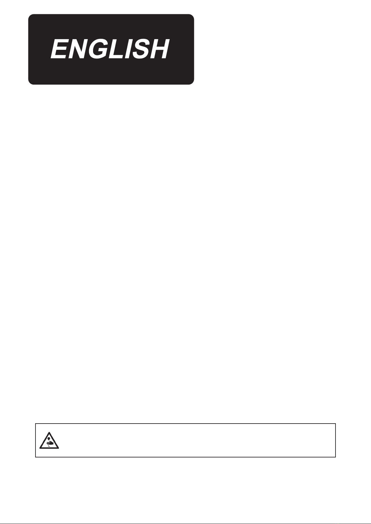
If any control device or program other than those specified in this Instruction Manual is
used, or if the adjustment method and usage specified in this Instruction Manual are not
followed, the maintenance person or user of this product can be exposed to hazardous
irradiation from the laser. If the human body or cornea is exposed to direct laser-irradia-
tion, health hazard such as burn of cornea, burn of retina, conjunctivitis, visual loss, burn
of skin, etc. and the fire can be caused.

– 1 –
1. This product cuts the material using the Level 4 no observation light continuous wave laser.
Wave length is 10.6 μm, maximum output is 100 W and the angle is 3.1 mrad. Only the per-
sons who have received professional training are allowed to use and handle this product.
Be sure to contact our After-Sale Service staff if you want to carry out maintenance and / or
repair of this product. Professional staff who has received professional training in JUKI to
gain experience of the relevant work will carry out maintenance / repair of your product.
1. SAFETY PRECAUTIONS
2. Whenever you use of this product or carry out maintenance / repair of it, be sure to wear
safety goggles. Use the safety goggles that satisfy the following criteria or that are provided
by the manufacturer.
Safety goggles selection criteria :
1. CE Marking is obtained
2. Visible light transmittance VLT>60%
3. Applicable wave length : 10.6μm
4. Protective characteristics : Light absorption type CO2 laser safety goggles or light reflec-
tion type CO2 laser safety goggles
5.Protection level : OD5+
3. Safety-mark attachment positions and meaning of icons and expressions
Any person other than
the professional engi-
neer is not allowed to
detach the cover.
Avoid direct exposure or
disperse exposure of the
eyes and skin to radia-
tion.

– 2 –
DANGER label
Avoid direct exposure or
disperse exposure of the
eyes and skin to radia-
tion. This product is a
Class 4 laser product.
DANGER label
This product causes
Class 4 laser beam ex-
posure. When you have
detached the cover, be
sure to avoid direct ex-
posure or disperse expo-
sure of the eyes and skin
to radiation.
Any person
who has not
received profes-
sional training
is not allowed to
touch the keys.
Twist counterclockwise:
Laser maintenance
mode
Twist clockwise:
Laser operation mode
Any person other than the profes-
sional engineer is allowed to carry
out adjustment. Do not remove the
cover while the laser is in opera-
tion.
CAUTION label
This is the laser exit port.
Warning label against
pinching
This label indicates that
there is a risk of pinching
hands between the sew-
ing machine and the laser
device mechanism.

– 3 –
1-1. Precautions to be taken when installing or adjusting the laser
1) If the laser intensity is excessively high, take care not to directly look into the laser in order to protect
your eyes. Be sure to wear safety goggles during work.
2) Take care not to irradiate the mirror surface with laser light in order to prevent reflection.
3) Laser current during the adjustment: Adjustment of the laser current during adjustment is prohibited.
The factory-set value at the time of shipment must be used as the standard value.
4) Be sure to use the adjustment mode when you adjust this product. (Refer to "5-5. Adjusting the
laser" p.21.)
5) Visible angle during work or adjustment (See the figure given below)
No observation
25°
Cutting position

– 4 –
Supplementary materials
1) Laser head
4) Cooling water tank
3) Suction fan
5) Power switch
Outdoor
Indoor
6) Suction pipe
A: Reflecting mirror of the laser
B: Focusing lens of the laser
C: Laser tube
It is prohibited to observe the laser
tube with an optical telescope or
directly look at the optical path while
the laser is in operation, from the
locations as shown in the figure.
1-2. Precautions to be taken when using the laser
1) Be sure to check the head section of the laser to clean it up to remove the accumulated combustion
impurity every working day before commencing the work.
2) Check atmospheric pressure and adjust it to 0.5 - 0.55 MPa every working day before commending
the work.
3) Be sure to check whether the cooling water tank and suction fan of the equipment normally operate
and also check the suction fan for abnormal noise and the cooling water tank for errors every work-
ing day before starting the work.
4) Be sure to check the cooling water tank of the laser contains an adequate amount of commercially
available pure water.
5) Turn OFF the power switch every working day at the end of the work.
6) Be sure to place the exhaust pipe of the suction fan in an outdoor location and attach a combustion
deodorizing filter to its outer connector.
7) This product is a Level-4 no observation light laser product. Anybody who has not received the pro-
fessional training must remain away from this product to protect against injury.
8) Whenever you want to carry out maintenance / repair of the laser equipment of this product, be sure
to contact our After-Sale Service Department. The professional staff who has received professional
training in JUKI to gain experience of the relevant work will carry out maintenance / repair of your
product.
B
A
C

– 5 –
2. MAINTENANCE
1) Observe the cooling water tank of the laser to check whether the water normally circulates in the
tank to ensure that the laser tube is not clogged inside.
2) Wipe the reflecting mirror surface with alcohol once every half month to keep it clean and to im-
prove its reflecting effect. Wipe the focusing lens inside the irradiation cylinder with alcohol from
time to time to keep it clean. (Refer to "2-1. Care for the lens" p.6 for details.)
3) Replace the laser tube based on the frequency of use. If the laser tube fails to satisfy the require-
ments for cutting the material, change the laser tube with an appropriate one.
4) For the cooling water tank of the laser tube, change the pure water (approximately 5L - 6L) in the
tank periodically once every three month.
5) The water in the cooling water tank of the laser tube should be changed every time the laser tube
is changed together. The tank uses approximately five to six liters of commercially available pure
water.
6) Check the hose of the tank and laser tube periodically once every three months and change it with
a new one if necessary in order to prevent a broken tube from negatively affecting smoking and
cooling.
7) Adjust / calibrate the laser path once every six months to ensure that the laser beam is focused
without distortion.
8) After you have used the laser for four hours, remove the screw indicated with the arrow in the pho-
tograph. Pull out the drawer of the dust sucking box to clean it up (for removal of dust) in order to
prevent a fire from occurring.
9) Thoroughly inspect and carry out cleaning of the following parts every time you have used the laser
for eight hours to prevent accumulation of dust and deterioration of the tube, thereby preventing a
fire from occurring. In some cases, blow the relevant parts with an air blower or disconnect the hose
to remove dust.
①Clean up litter in the upper smoking tube.
②Clean up litter in the lower smoking tube (Loosen the screw in the cover on the table. Clean up
litter at the tube opening and in the tube with a tool or small wooden stick).
③Clean up litter accumulated in the dust suction opening, outlet and exhaust pipe of the suction
fan.
10) Immediately carry out inspection and maintenance according to the instructions displayed on the
operation panel.
Service life of the laser tube: Approximately six months. Service life of the focusing lens and reflect-
ing mirror: Approximately one year. Periodical cleaning is required to prevent foreign matters from
attaching them.

– 6 –
8) Dust sucking box
9) Upper suction tube
9) Lower suction (Cover)
9) Lower suction tube
Outlet
Upper suction
tube
Air outlet
1) Loosen two setscrews ❶of the laser protec-
tive cover to remove the cover.
❶❶
2-1. Care for the lens
Laser protective
cover
2) Turn OFF the air and
disconnect the air pipe.
Then, turn the connect-
ing tube under the neck
of the laser to remove
it.
Air pipe
Connecting tube
under the neck
of the laser
Disassem-
bled state
Supplementary materials
WARNING :
Be sure to always turn OFF the power to the sewing machine and laser before disassembly and as-
sembly.

– 7 –
4) Wipe the lens you have removed with alcohol
using a piece of clean waste cloth.
Check to make sure that there is no abnormal-
ity such as dirt or flaws on the surface of the
lens.
Disassem-
bled state
Be sure to loosen the
nut with a jig that is
suitable for the nut
slot shape.
Never use a coin
to disassemble or
assemble the lens
components since the
coin will damage the
lens.
3) Loosen the nut to remove the
lens.
Nut
Rubber
Lens
5) Reassemble the lens components.
Nut
Rubber
Lens
Top
Bottom
Reassemble the lens components pay-
ing attention to the mounting order and
orientation of the lens components.
* Convex surface
of the lens should
be on the top.
Nut tightening
torque 5 to 10 kgcm

– 8 –
6) Turn the connecting tube under the neck of the
laser to install it.
Then, perform air piping.
❶❶
7) Attach two setscrews ❶to the laser protective
cover to secure the cover.
8) Lastly, carry out cutting test on the laser and
adjust the laser if necessary.
Clearance between the
cover and the top surface
of the table 5 to 8 mm
Assembly torque 35 kgcm

– 9 –
3-1. Circuit diagrams
3. ELECTRICAL SAFETY
Note: Intersection of lead wires is not yet connected
Intersection of lead wires is connected
All of the base lines are connected on the same base.

– 10 –
4-1. Installing the laser power supply
4. INSTALLATION
1) Securing the laser power supply
To secure the laser power supply, align screws
A(Fig. 1) with the tapped holes of the slider
nuts B(Fig. 1) and tighten the two screws on
the right and left of the laser power supply.
BBAA
BB
Fig. 1

– 11 –
2) Installing the converter
❶❷❸❹❺
No. Part name Qty Remarks
❶Converter 1 ME300
❷Mounting plate 1
❸Hexagon socket head cap
screw 2
❹T-type bolt 2
❺Nut M8 2
❷❷
❸❸
Secure converter ❶to mounting plate ❷with
hexagon socket head cap screws ❸.
❺❺
❹❹Attach T-type bolts ❹and nuts ❺to mounting
plate ❷as shown in the figure.
❺❺❺❺
❶❶
❷❷
Install converter ❶to the sewing machine frame.
Install it to the position as shown in the figure and
tighten nuts ❺to secure it.

– 12 –
3) Wiring the cable between the air
blower and the converter
❻❻
Open cover ❻of the converter.
❼❼
❽❽
Connect air blower ❼and converter ❶with air
blower connection cables ❽(4-core cable: Black,
blue, red, green/yellow).
[Connection on the converter side]
Connect the black core wire of cable ❽to the "W/
T3" terminal.
Connect the blue core wire of cable ❽to the "U/
T1" terminal.
Connect the red core wire of cable ❽to the "V/
T2" terminal.
Ground terminal
Connect the green/yellow core wire of cable ❽to
the ground terminal located at the lower right part
of the converter.

– 13 –
[Connection on the air blower side]
Connect the black core wire of cable ❽to the W
terminal.
Connect the blue core wire of cable ❽to the V
terminal.
Connect the red core wire of cable ❽to the U
terminal.
4) Wiring the cable between the electrical control
box and the converter
Ground terminal
Cable col-
or
Air blower Converter
Blue V U/T1
Black W W/T3
Red U V/T2
Green / Yel-
low
Ground termi-
nal
Ground terminal
Table 1. Connection between the air blower
and the converter
Connect the electrical control box and the con-
verter with the electrical cable ❾(2-core: Blue,
brown).
[Connection on the converter side]
Connect the blue core wire of cable ❾to the
"MT1" terminal of the terminal block.
Connect the brown core wire of cable ❾to the
"DCM" terminal of the terminal block.
❾❾
[Connection on the electrical control box side]
Connect cable ❾to the connector of the elec-
trical control box.
Cable col-
or
Converter Electrical con-
trol box
Blue MT1 OUT9
Brown DCM 24V
Table 2. Connection between the electrical
control box and the converter

– 14 –
[Switch setting]
Change over the setting of the switches located
inside the converter; i.e., switch to "Upper:
PNP" and switch to "Lower: 0 - 10 V".
[Wiring route]
Pass the cables from the side face to the back of the sewing machine and pull them into the electrical
rack.

– 15 –
5) Wiring the cable between the power supply
terminal block and the converter
Connect power supply terminal block located
inside the electrical rack and the converter with
power supply connection cable (3-core: Blue,
brown, green/yellow).
[Connection on the converter side]
Connect the brown core wire of cable to the "R/
L1" terminal of the terminal block.
Connect the blue core wire of cable to the "S/
L2" terminal of the terminal block.
Ground terminal
Connect the green/yellow core wire of cable to
the ground terminal.
112233445566778899
[Connection on the power supply terminal
block side]
Connect the blue core wire of cable to "7" of
power supply terminal block .
Connect the brown core wire of cable to "3" of
power supply terminal block .
Connect the green/yellow core wire of cable to
"9" of power supply terminal block .
Cable col-
or
Converter Power supply
terminal block
Blue S/L2 7
Brown R/L1 3
Green / Yel-
low
Grounding 9
Table 3. Connection between the power supply
terminal block and the converter

– 16 –
When you turn ON the power to the sewing machine, the power
to the converter is turned ON.
While the power to the converter is in the ON state, press the
"ENTER" button.
Press the "▲" button to adjust the numeric value on the LED to
"00.20".
6) Setting the converter
In this paragraph, setting of the parameter setting No. "0.20" is
described. Set the parameters in Table 1 in the same way as
described above.
Setting No. Value
0.17 14
0.20 7
0.21 1
1.12 4
Setting No. Value
1.13 5
1.35 60
1.52 60
Press the "ENTER" button.
Press the "▲" button to adjust the numeric value on the LED to
"7".

– 17 –
Press the "ENTER" button.
Press the "MODE" button twice.
Then, the LED display is changed over as illus-
trated in the figure on the left. Now, setting of the
converter is completed.

– 18 –
5-1. Tune ON the power
5. OPERATION
1) Insert the power cord plug into the socket
(supply voltage: 220 V ± 20 %, 50 Hz). Be
sure to ground the power cord for the sake
of safety.
2) Among the power switches (air switches) in
the control panel cabinet, the switch that is
located at the left side of the control panel
and has the identical-color upper and lower
cords (red and red, and black and black) is
the laser power supply switch ❶. (See Fig.
1.) Another air switch that is located at the
upper right corner in the control panel and
has different-color upper and lower cords
(red and brown, and blue and black) is the
sewing machine power supply air switch ❷.
(See Fig. 2.)
Put the compressed air from the air source (air
pressure: 0.5 - 0.55 MPa) to the air supply suction
inlet 64 by means of the air tube (specification: 8
× 5 mm).
5-2. Starting the air supply
❷
❶
Fig. 1 Fig. 2
This manual suits for next models
1
Table of contents
Other JUKI Measuring Instrument manuals
Popular Measuring Instrument manuals by other brands

Rohde & Schwarz
Rohde & Schwarz R&S FSV3-K106 user manual

Camille Bauer
Camille Bauer SIRAX BM1200 Device handbook

Atdec
Atdec ATD-5544 owner's manual

National Instruments
National Instruments PXIe-5764 Getting started guide

Tektronix
Tektronix RSA7100A Quick start user manual

Befaco
Befaco BCMF3100 operating manual