Jula UT131 User manual

UT131 Palm Size Multimeter
-1-
UT131 Palm Size Multimeter
User Manual

UT131 Palm Size Multimeter
-2-
Ⅰ.Overview
The new generation UT131 series products redefine the performance standards for entry-level digital
multimeter. The innovative industrial design ensures the products have 2 meters impact resistance.
The new LCD display layout provides a clear display for better user experience. The UT131 series
ensure safe operation in CAT II 250 V environment.
The special features of each model are as follows:
UT131A: 2mF capacitance test function
UT131B: Battery test with status indicators
UT131C: Temperature test
UT131D: NCV test
Ⅱ.Open Box Inspection
Open the package box and take out the device. Please check whether the following items are
deficient or damaged and contact your supplier immediately if they are.
User manual -----------------------1 pc
Test leads ---------------------------1 pair
Protective case---------------------1 pc

UT131 Palm Size Multimeter
-3-
K-type Thermocouple ----------1 pc (UT131C only)
Warning:
Please carefully read “Safe Operation Rule” before using the device.
Ⅲ.Safe Operation Rule
1). Safety certification
This device strictly follows the CE standards: EN 61010-1: 2010, EN 61010-2-030:2010, EN
61326:2013, as well as CAT II: 250V, RoHS, pollution grade II, and double insulation standards.
2). Safety instructions and Precautions
1. Do not use the device if the device or test leads appear damaged or if you suspect that the
device is not operating properly. Pay particular attention to the insulation layers.
2. If the test leads are damaged, it must be replaced with one of the same type or the same
electrical specification.
3. When measuring, do not touch exposed wires, connectors, unused inputs, or the circuit being
measured.
UT131 Palm Size Multimeter
-4-
4. When measuring the voltage higher than 60 VDC or 30 VACrms, keep your fingers behind the
finger guard on the test lead in order to prevent electric shock.
5. If the range of the voltage to be measured is unknown, the maximum range should be
selected and then gradually decreased.
6. Never input voltage and current exceeding the value listed on the device.
7. Before switching ranges, make sure to disconnect the test leads with the circuit to be tested. It
is strictly prohibited to switch the Ranges during the measurement.
8. Do not use or store the device in high temperature, high humidity, flammable, explosive or
strong magnetic field environments.
9. Do not change the internal circuit of the device in order to avoid the damage to the device and
users.
10. To avoid false reading, replace the battery when the battery indicator appears.
11. Use dry cloth to clean the case, do not use detergent containing solvents
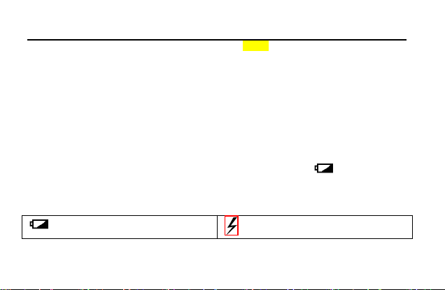
Ⅳ.Electrical Symbols
low battery
High voltage warning

UT131 Palm Size Multimeter
-5-
Electrical ground
AC/DC
Double insulation
Warning
Ⅴ.Specification
1. The maximum voltage between the input terminal and the ground: 250Vrms
2. 10A terminal: Fuse 10 A 250 V Fast fuse Φ5×20 mm
3. mA/μA terminal: Fuse 200 mA 250 V Fast fuse Φ 5×20 mm
4. Max display 1999, over range display “OL”, update rate: 2~3 times/second
5. Range select: Auto range UT131A; Manual range UT131B/C/D
6. Backlight: manual on, auto shut off after 30 seconds
7.Polarity: "-" symbol displaying on screen represents negative polarity signal.
UT131 Palm Size Multimeter
-6-
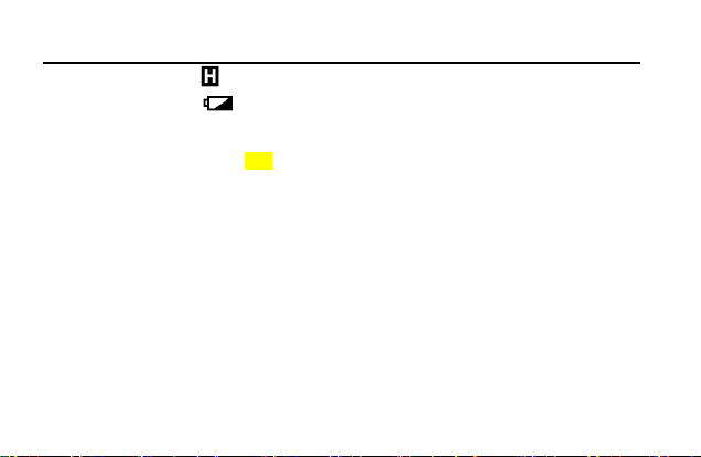
8. Data hold function: symbol displays on screen when data hold function is activated
9. Low battery power: symbol displays on screen when battery power is low
10. Battery: AAA 1.5V * 2
11. Operating temperature: 0~40˚C (32˚F~104˚F)
Storage temperature: -10~50˚C (14˚F~122˚F)
Relative humidity: 0˚C~30˚C: ≤75% RH, 30˚C~40˚C: ≤50% RH
Operating altitude: 0 ~ 2000m
12. Dimension: (134×77×47) mm
13. Weight: about 206g (battery included)
14. Electromagnetic compatibility:
In fields with less than 1 V/m radio frequency, the total accuracy = designated accuracy + 5% of
measurement range
UT131 Palm Size Multimeter
-7-
In fields with more than 1 V/m radio frequency, the accuracy is not specified.
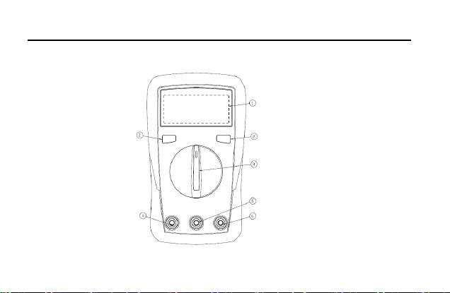
Ⅵ. Structure (see Figure 1)
Figure 1

UT131 Palm Size Multimeter
-8-
1. Display screen
2. Function keys
3. Functional dial
4. 10A input jack
5. COM jack
6. Remaining inputs jack
Ⅶ.Key Functions
1) UT131A:
* SEL/REL: press this key to switch between AC and DC modes for mV , I , and REL

UT131 Palm Size Multimeter
-9-
positions.
* : Press to enter or exit data hold mode. Long press over 2 seconds to turn on/off
backlight.
2) UT131B/C/D:
*. HOLD/SEL: Press to enter or exit data hold mode
In continuity/diode mode, press to cycle switch between the two modes
* : Press to turn on/off backlight.
Ⅷ.Operations
To avoid false reading, replace the battery if the battery low power symbol appears. Also pay
special attention to the warning sign beside the test lead jack, indicating that the tested

UT131 Palm Size Multimeter
-10-
voltage or current must not exceed the values listed on the device.
1. AC/DC voltage measurement (see Figure 2b)
1) Switch the dial to “V~” position.
2) Insert the black test lead into the COM jack, the red test lead into the “VΩmA” jack. Connect
test leads with the load in parallel.
Table of contents
Other Jula Multimeter manuals


Popular Multimeter manuals by other brands


Gossen MetraWatt
Gossen MetraWatt METRAmax 6 operating instructions

PeakTech
PeakTech 4000 Procedure of calibration

YOKOGAWA
YOKOGAWA 90050B user manual

Gossen MetraWatt
Gossen MetraWatt METRALINE DMM16 operating instructions

Fluke
Fluke 8846A Programmer's manual

Tempo Communications
Tempo Communications MM200 instruction manual


