5
with the highest range.
4. If meter indication is in the lower half of the scale and falls within the
range of a lower scale, reset selector switch to the lower range for
greatest accuracy.
5. If the meter won’t work at all, check the fuse located on the PCB. If it’s
blown, replace it. (See fuse replacement.)
6. Avoid placing the meter where extreme shock or continuous vibration
is encountered and do not store in excessively hot or damp places.
Although very rugged, the meter is a sensitive measuring device and
should be handled carefully & properly.
7. Do not check resistance, transistor, diode, LED, or capacitance when
live voltage or current input across the circuit.
8. When the meter is not in use, keep the selector switch to the “OFF”
range position, this provides direct short across meter movement for
minimum needle bounce when transporting meter.
9. If you should accidentally apply excessive voltage or current on a
certain range, disconnect the leads from the circuit as quickly as
possible, check instrument operation on that range by applying peoper
input. If the meter does not operate properly, check fuse. If it is blown
replace it. (See fuse replacement.)
OPERATION PROCEDURES
DC Voltage Measurement
WARNING: USE EXTREME CARE WHEN MAKING
MEASUREMENTS FOR HIGH VOLTAGE. DO NOT TOUCH
TERMINAL OR PROBE ENDS.
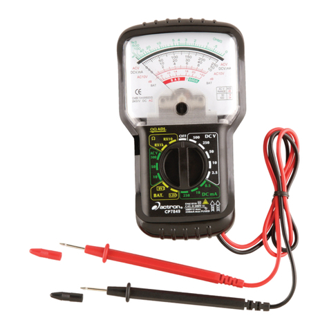
1. Set the selector switch to the appropriate DCV range to be used.
2. Connect the BLACK test lead to the “-COM” jack and the RED test lead
to the “+” jack.
3. If you know the polarity of the circuit to be tested, connect the black
probe to the negative side.
4. If you don’t know the polarity, connect the probes to opposite sides of the
circuit and watch the pointer. If it goes to the left, reverse the probes. The
RED probe will be connected to the positive.
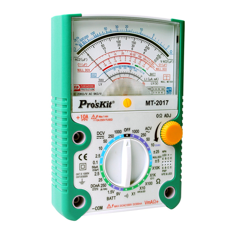
5. Check the needle position and the get the reading on V.A scale.
Null DCV (Central Zero) Measurement
At these two ranges, it can automatically judge the polarity of circuit as the
pointer can move to the center line and become a Null meter.
1. Set the selector switch to the DCV ±5V or 25V range.
2. Connect the BLACK test lead to the “-COM” jack and the RED test lead to
the Red “+” jack.
3. Set the Zero Ω adjustor to place the pointer exactly to the Central Zero
position if need.


