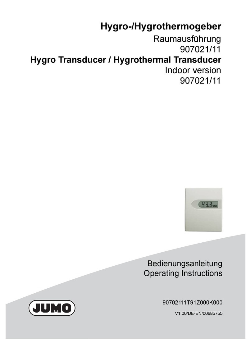
JUMO 907020/11 User manual

Hygro- und Hygrothermogeber (kapazitiv)
Raumausführung Grundtyp 907020/11
nach Typenblatt 907020
Hygro / Hygrothermo Transducers (Capacitive)
Indoor version basic type 907020/11
according to data sheet 907020
Betriebsanleitung
Operating Manual
2013-12-04

Hygro- und Hygrothermogeber (kapazitiv)
Raumausführung 4...20mA oder 0...10VDC
nach Typenblatt 907020
Wartung - Einsatzhinweis - Schmutzeinüsse
Aggressive und lösungsmittelhaltige Medien können je nachArt und Konzentration Fehlmessungen undAusfall verursachen.
Niederschläge, die einen wasserabweisenden Film über dem Feuchtesensorelement bilden (Harzaerosole, Lackaerosole,
Räuchersubstanzen usw.), sind schädlich.
Allgemein
Diese Messumformer erfassen die rel. Luftfeuchte und Temperatur und eignen sich besonders für Anwendungen im Kli-
mabereich. Ein kapazitives Feuchtemesselement erfaßt die Luftfeuchtigkeit und setzt diese in Strom- (4...20mA) oder
Spannungssignale (0...10VDC) um. Die Bauform ist für Raummontage ausgelegt. Zur Erfassung der Temperatur dient ein
Platin-Temperatursensor nach DIN EN 60751, dessen Signal ebenfalls umgeformt wird.
Das Montagegehäuse der Raumversion verfügt über einen einfachen, robusten Verschlussmechanismus. Die Transmitter-
elektronik bendet sich im Oberteil des Gehäuses. Nach der Montage des Unterteils an der gewünschten Stelle kann das
Einhängen und Verschließen des Oberteils jederzeit später ohne Werkzeug erfolgen.
Technische Daten
Feuchte
Ausgangsbereich 0..100%rF
Genauigkeit bei 23°C ±2,5%rF (40...60%rh)
±3%rF (10...40%rh oder 60...90%rF)
mittlerer Temperaturkoefzient ±0,05 %rF/K bezogen auf 23°C
Temperatur
Ausgangsbereich -30...+70°C, 0...+50°C oder 0...+100°C
Messgenauigkeit bei 10...40°C ±0,25 K (U)
±0,4 K (I)
Spannungsversorung
für U- Ausgang 0...1V 6...30 V DC / 6...26 V AC
für U-Ausgang 0...10V 15...30 V DC / 13...26 V AC
für I-Ausgang 4...20 mA 10...25 V DC
Lastwiderstand RL≥ 10 kΩ
(Spannungsausgang)
Bürde RL(Stromausgang)
Messmedium Luft, drucklos, nicht aggressiv
Einsatztemperatur -30...+60°C (auch für Display-Version)
Lagertemperatur -40...+85°C
Befestigung Bohrungen im Gehäuseboden
Einbaulage Die Sensoren sind so zu montieren, dass die Raumluft durch die im Gehäusedeckel
bendlichen Luftschlitze von unten nach oben ungehindert hindurchströmen kann.
Anschlussklemmen für Leiterquerschnitte max. 1,5mm2
Kabelanschluss über Unterputzdose oder Aufputzkabel
Elektromagnetische Verträglichkeit EN 61326-1 und EN 61326-2-3
Gehäuse ABS RAL 9003
LCD-Anzeige optional, 2-zeilig, 3 Stellen + 1 Dezimalstelle, Ziffernhöhe ca. 8 mm
Schutzart IP 30D
Gewicht ca 0,058 kg
„Änderungen vorbehalten“
Typ 907020/11
Ω= Versorgungsspannung - 10 V
0,02 A ± 50 Ω

General Information
These measuring transducers register relative humidity and temperature and are suitable for applications in climatisation. A
capacitive humidity measuring element registers the relative humidity and converts it in current (4...20 mA) or voltage (0...10
V) signals. This version is designed for mounting in rooms. The temperature is registrated by a platinum temperature sensor
according to DIN EN 60751 whose signal is also converted.
The housing of the room version has a simple and robust closing mechanism. After mounting the base part, the top which
contains the transmitter electronics, can be easily clipped into place and pressed shut without any tool.
Technical data
Humidity
Output range 0..100%rh
Accuracy at 23°C ±2,5%rh (40...60%rh)
3%rh (10...40%rh or 60...90%rh)
Inuence of temperature ±0,05 %rh/K ref. to 23°C
Temperature
Output range -30...+70°C, 0...+50°C or 0...+100°C
Accuracy at 10...40°C ±0,25 K (voltage)
±0,4 K (current)
Voltage supply
for voltage-output 0...1V 6...30 V DC / 6...26 V AC
for voltage-output 0...10V 15...30 V DC / 13...26 V AC
for current-output 4...20 mA 10...25 V DC
Load resistance RL≥ 10 kΩ
(voltage output)
Load RL(current output)
Measuring medium air, pressureless, non-aggressive
Operating temperature -30...+60ºC (also for display version)
Storage temperature -40...+85°C
Fixing slots in housing base
Mounting position The sensors should be mounted such that air in the room can ow upwards
unimpeded through the ventilation slots in the housing cover.
Connecting terminals for conductor cross sections max. 1.5mm²
Cable connection by in-wall junction box or on-wall calbe
Electromagnetic compatibility EN 61326-1 and EN 61326-2-3
Housing ABS RAL 9003
LCD display optional, 2 lines, 3 digits + 1 decimal place, digit height approx. 8 mm
Degree of protection IP 30D
Weight approx. 0.058 kg
”Subject to modications”
Hygro und Hygrothermo Transducers (capacitive)
room version 4...20mA or 0...10VDC
according to data sheet 907020
Maintenance - Instructions for use - Effect of pollutants
Depending on type and concentration, agents that are corrosive and contain solvents, can result in faulty measurements
and can cause the sensor to break down. Substances deposited on the sensor (e. g. resin aerosols, lacuer aerosols, smoke
deposits etc.) are damaging as they eventually form a water-repellent lm.
Type 907020/11
Ω= voltage supply - 10 V
0,02 A ± 50 Ω

Abmessungen /Dimensions
Anschlussbelegung / Connection diagram
Öffnen des Gehäuses / Opening the housing
81
25,7
1
11
10,5
81
47,5
81
25,7
1
11
10,5
81
47,5
Position Montage an einer für die Klimamessung repräsentativen Stelle. Messkammer im
Luftstrom. Die Nähe von Heizkörpern, Türen und Außenwänden sowie direkte
Sonneneinstrahlung sind zu meiden.
Montage auf
Unterputzdose
Anschluss an
Aufputz- und
Unterputzkabel
Bei der Montage des Gerätes auf eine Unterputzdose ist durch entsprechende
Abdichtung zu vermeiden, dass über die Unterputzdose Fremdluft auf die Messe-
lemente des Gerätes gelangt.
Bei Anschluss an ein Unterputzkabel ist zur Kabeldurchführung der vorgestanzte
Teil des Gehäusebodens auszubrechen. Bei Anschluss an ein Aufputzkabel können
die Stege an der vertiefte Stelle in der Gehäuseseite ausgebrochen werden.
Montagehinweise
Position Install the sensor at a place where characteristic levels of humidity occur. The
measuring chamber should be located in streaming air. Avoid installation next to
heaters, doors or on outer walls. Avoid places exposed to the sun.
Mounting
on a patress
Connection to
surface and
in-wall cable
When mounting the sensor on a patress, avoid external air getting onto the measu-
ring elements of the sensor by sealing it appropriately.
In order to insert the connection cable, prise the pre-cut part of the housing‘s base
part open.
In order to insert a on-wall cable, the bars of the immerged part of the housings
side can be removed.
Mounting instructions
Bohrbild / Drilling pattern
907020/11-1-00-065-xxx
907020/11-1-00-005-xxx 907020/11-2-xx-005-xxx 907020/11-2-xx-065-xxx
81
81
60
12
4,3
3
41
37
1
2
3
V+ 10…25 V DC
Out RH 4…20 mA
DIK 4…20 mA
1
2
3
Out T 4…20 mA
V+ 10…25 V DC
Out RH 4…20 mA
1
GND
2
3
4
Out RH 0…10 V
V+ 15…30 V DC /
13…26 V AC
1
Out T 0…10 V
GND
2
3
4
Out RH 0…10 V
V+
15…30 V DC
/
13…26 V AC

User instructions
Dew formation Dew formation and splashes do not damage the sensor, although corrupted measure-
ment readings are recorded until all the moisture on and directly around the sensor
element has dried up.
Damaging inuences Depending on type and concentration, agents that are corrosive and contain solvents,
can result in faulty measurements and can cause the sensor to break down.
Substances deposited on the sensor (e. g. resin aerosols, lacuer aerosols, smoke
deposits etc.) are damaging as they eventually form a water-repellent lm.
Anwenderhinweise
Betauung Betauung und Spritzwasser schaden dem Sensor nicht, führen aber bis zur restlosen
Trocknung des Sensorelements und seiner unmittelbaren Umgebung zu
Messfehlern.
Schädliche
Einüsse
Aggressive und lösungsmittelhaltige Medien können je nach Art und Konzentration
Messfehler und Ausfall verursachen.
Niederschläge, die einen wasserabweisenden Film über dem Sensorelement bilden
(Harzaerosole, Lackaerosole, Räuchersubstanzen usw.), sind schädlich.
Montagehinweise
Anschluss Der elektrische Anschluss darf nur von Fachpersonal vorgenommen werden.
Im Transmittergehäuse benden sich empndliche Bauteile. Beim Öffnen des
Gehäuses sind die elektrostatischen Vorsichtsmaßnahmen (ESD) zu beachten.
Bitte beachten Sie die der Versorgungsspannung angepasste Bürde bei Sensoren
mit Stromausgang.
Zuleitungen zum Sensor dürfen nicht parallel zu starken elektromagnetischen Feldern
verlegt werden.
Bei möglichen Überspannungen Überspannungsschutzgeräte installieren.
Connection The electrical connection must be carried out by qualied personnel only.
The sensor contains sensitive electrical components. When opening the housing, make
sure you comply with the electrostatic discharge precautions (ESD).
Pay attention to the load according to the operating voltage when using sensors with
a current output.
Lines to and from the sensor must not be installed parallel to strong electromagnetical
elds.
If there is any chance of an electrical surge, please install surge protection devices.
Mounting instructions
ESD-Schutzhinweis
Die Sensoren der D-Serie enthalten Bauteile, die durch Einwirkung elektrischer Felder oder durch Ladungsausgleich beim
Berühren beschädigt werden können.
Folgende Schutzmaßnahmen sind unbedingt zu beachten, wenn ein Sensor zum Anschluss oder zum Vor-Ort-Abgleich
geöffnet werden soll:
• Stellen Sie vor Öffnen des Gehäuses einen elektrischen Potentialausgleich zwischen sich und ihrer Umgebung her.
• Achten Sie darauf, dass dieser Potentialausgleich besteht, während Sie bei geöffnetem Gehäuse arbeiten.
ESD protection advice
The sensors of the D Series contain components, which can be damaged by the effects of electrical elds or by charge equa-
lisation when touched.
The following protective measures must be taken when the housing of the sensor is to be opened for connection:
• Before opening the housing of the sensor, ensure electrical potential equalisation between you and your
environment.
• Pay particular attention to ensure that this potential equalisation is maintained while you are working with the
opened housing.

JUMO GmbH & Co. KG
Moritz-Juchheim-Straße 1
36039 Fulda, Germany
Technischer Support Deutschland:
Telefon:
Telefax :
E-Mail:
Internet:
+49 661 6003-722/724
+49 661 6003-601/688
www.jumo.net
Telefon:
Telefax :
E-Mail:
+49 661 6003-9135
+49 661 6003-881899
Lieferadresse:
Mackenrodtstraße 14
36039 Fulda, Germany
Postadresse:
36035 Fulda, Germany
JUMO Mess- und Regelgeräte Ges.m.b.H
Pfarrgasse 48
1230Wien, Austria
Technischer Support Österreich:
Telefon:
Telefax :
E-Mail:
Internet:
+43 1 610610
+43 1 6106140
www.jumo.at
Telefon:
Telefax :
E-Mail:
+43 1 610610
+43 1 6106140
JUMO Mess- und Regeltechnik AG
Laubisrütistrasse 70
8712 Stäfa, Switzerland
Technischer Support Schweiz:
Telefon:
Telefax :
E-Mail:
Internet:
+41 44 928 24 44
+41 44 928 24 48
www.jumo.ch
Telefon:
Telefax :
E-Mail:
+41 44 928 24 44
+41 44 928 24 48

JUMO GmbH & Co. KG JUMO Instrument Co. Ltd. JUMO Process Control, Inc.
Street address:
Moritz-Juchheim-Straße 1
36039 Fulda, Germany
Delivery address:
Mackenrodtstraße 14
36039 Fulda, Germany
Postal address:
36035 Fulda, Germany
Phone: +49 661 6003-0
Fax: +49 661 6003-607
E-mail: [email protected]
Internet: www.jumo.net
JUMO House
Temple Bank, Riverway
Harlow - Essex CM20 2DY, UK
Phone: +44 1279 63 55 33
Fax: +44 1279 63 52 62
E-mail: [email protected]
Internet: www.jumo.co.uk
6733 Myers Road
East Syracuse, NY 13057, USA
Phone: 315-437-5866
1-800-554-5866
Fax: 315-437-5860
E-mail: [email protected]
Internet: www.jumousa.com
This manual suits for next models
9
Table of contents
Other JUMO Transducer manuals
Popular Transducer manuals by other brands

TR-Electronic
TR-Electronic LMRI-46 200 PB manual

TSI Instruments
TSI Instruments 8465 Operation and service manual

WIKA
WIKA CPD8500 Utility manual

controlair
controlair 595XP Installation, operation and maintenance instructions

Humminbird
Humminbird ICE HELIX Series installation guide

ADInstruments
ADInstruments MLT844 quick start guide