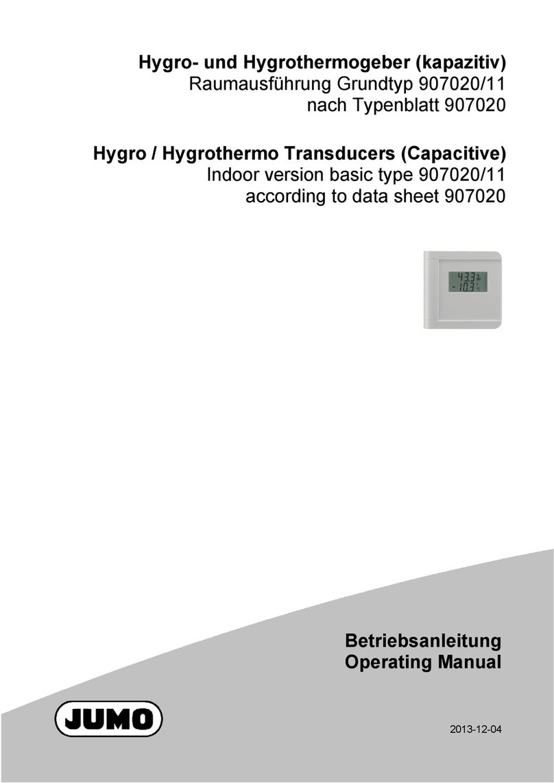
JUMO HC103 User manual

Hygro-/Hygrothermogeber
Raumausführung
907021/11
Hygro Transducer / Hygrothermal Transducer
Indoor version
907021/11
Bedienungsanleitung
Operating Instructions
90702111T91Z000K000
V1.00/DE-EN/00685755

BEDIENUNGSANLEITUNG
907021/11 – Messumformer für Feuchte und Temperatur
BA_907021-11 // v1.1 // Modification rights reserved // 350173
Der Messumformer ist für die exakte Erfassung von Feuchte und Temperatur bestimmt. Das formschöne funktionelle
Gehäuse ist für die direkte Wandmontage geeignet und ermöglicht eine einfache Installation und im Servicefall einen
raschen Wechsel der Sensoreinheit.
Extreme mechanische Beanspruchungen und unsachgemäße Handhabung sind unbedingt zu vermeiden
ALLGEMEIN
TECHNISCHE DATEN
(Änderungen vorbehalten)
Messwerte
Relative Feuchte
Sensor HC103
Analogausgang 0...100% rF 0-10 V -1 mA < IL< 1mA
4-20 mA (Zweidraht) RL< (UV-10)/0,02 < 500 Ohm
Arbeitsbereich1) 0...95% rF
Genauigkeit bei 20 °C und UV=24V DC ±2% rF (40...60% rF) ±3% rF (10...90% rF)
Temperaturabhängigkeit bei 60% rF typisch 0,06% rF / °C
Temperatur aktiv 0-10 V -1 mA < IL< 1mA
4-20 mA (zwei Draht) RL< (UV-10)/0,02 < 500 Ohm
Genauigkeit bei 20 °C und UV=24VDC ±0,25 °C (Spannung) ±0,4 °C (Strom)
Temperatur passiv
Typ T-Sensor siehe Bestellcode
Allgemein
Versorgungsspannung (UV)
für 0 - 10 V 15 - 40 VDC oder 24 VAC ±20%
für 4 - 20 mA 28V DC > UV> 10 + 0,02 x RL(RL<500 Ohm)
Stromaufnahme bei DC Versorgung typ. 4 mA
bei AC Versorgung typ. 15 mAeff
Anschluss Schraubklemmen max. 1,5 mm2
Gehäusematerial Polycarbonat
UL94HB zugelassen
Schutzart IP30
Anzeige bei Version 907021/11-02 Feuchte / Temperatur alternierend
bei Version 907021/11-03 Feuchte
Elektromagnetische Verträglichkeit EN61326-1 EN61326-2-3
FCC Part 15 Class B ICES-003 Issue 5 ClassB
Temperaturbereiche Betriebstemperatur: -5...+55 °C
Lagertemperatur: -25...+60 °C
1) Bitte Arbeitsbereich des HC103 beachten!

ANSCHLUSSBILD
ABMESSUNG / INSTALLATION
MONTAGEBOHRUNGEN
Die Elektronik befindet sich im Deckel, welcher sich leicht öffnen und schließen lässt, sobald die hintere Abdeckung an der Wand
befestigt (D = Montagebohrungen) und verkabelt ist.
Öffnen des Gehäuses:
Zapfen A eindrücken, bis sich der Deckel öffnen lässt. Verwenden Sie einen Schraubendreher
oder einen Stift.
Schließen des Gehäuses:
Deckel in Nut B einsetzten und in Richtung C schließen, bis der Zapfen A einrastet.
Wichtig!
Um den Deckel bzw. die Elektronik vor typischer Baustellenverschmutzung zu schützen, sollte
dieser erst nach Abschluss der Bauarbeiten montiert werden.
Da der Messumformer normalerweise auf einer Unterputzdose montiert wird, ist es wichtig
diese abzudichten, um Verfälschungen der Messergebnisse durch falschen Lufteintritt in das
Gehäuse entlang der elektrischen Leitungen zu vermeiden.
B
C
A
D
Abmessungen: 85 x 100 x 26 mm (BxHxT)
907021/11-2-34-065 907021/11-3-34-066
907021/11-3-34-067
907021/11-2-34-005 907021/11-3-34-006
907021/11-3-34-007

The Transmitter is designed for accurate measurement of humidity and temperature. The stylish, functional housing for
wall mounting makes easy installation and fast exchange of the sensing unit for service purposes possible.
Absolutely avoid extreme mechanical and unspecified strain!
GENERAL
MANUAL
907021/11 – Transmitter for Humidity and Temperature
TECHNICAL DATA
(Modification rights reserved)
Measuring Quantities
Relative Humidity
Humidity sensor HC103
Analogue output 0...100% RH 0-10 V -1 mA < IL< 1mA
4-20 mA (two-wire) RL < (UV-10)/0.02 < 500 Ohm
Working range1) 0...95 % RH
Accuracy at 20°C (68°F) and UV=24VDC ±2% RH (40...60% RH) ±3% RH (10...90% RH)
Traceable to intern. standards, administrated by NIST, PTB, BEV...
Temperature dependence at 60% RH typical 0.06% RH /°C (0.03% RH / °F)
Temperature (active output) 0-10 V -1 mA < IL< 1mA
4-20 mA (two wires) RL< (UV-10)/0.02 < 500 Ohm
Accuracy at 20°C (68°F) and UV=24VDC Voltage: ±0.25°C (±0.45°F) Current: ±0.4°C (±0.72°F)
Temperature (passive output)
Type of T-Sensor please see ordering guide
General Data
Voltage supply (UV)
for 0 - 10 V 15 - 40 VDC or 24 VAC ±20%
for 4 - 20 mA 28V DC > UV> 10 + 0.02 x RL(RL< 500 Ohm)
Current consumption for DC supply: typical 4 mA
for AC supply: typical 15 mAeff
Electrical connection screw terminals max. 1.5 mm2(AWG 16)
Housing material Polycarbonat
UL94HB approved
Protection class IP30
Display for 907021/11-02 version Humidity / Temperature alternating
for 907021/11-03 version Humidity
CE compatibility according EN61326-1 EN61326-2-3
FCC Part 15 Class B ICES-003 Issue 5 ClassB
Temperature ranges working temperature range: -5...55°C
(23...131°F)
storage temperature range: -25...60°C (-13...140°F)
1) Please refer to the working range of the HC103
BA_907021-11 // v1.1 // Modification rights reserved // 350173

DIMENSIONS / MOUNTING
The electronics are located in the front cover, which can be easily snapped on/off once the back cover is fixed onto the wall
( D = mounting holes) and wired.
Opening the enclosure
Press to release the latch A, till the enclosure can be opened. Use a screwdriver or a pen.
Closing the enclosure
Set the front cover into flute B, rotate it like C and press it onto the back cover till the latch A
snaps in.
Important
In order to protect the front cover and the electronics from typical
construction site pollution (such as painting of the walls) the front cover should be snapped on
only after the construction works are completed.
As the transmitter is generally mounted onto a conduit box, for accurate measurement results it
is important to tighten the conduit box for avoiding false air ingress (along the electrical tubes
inside the wall) into the enclosure.
B
C
A
D
Dimensions: 85 x 100 x 26 mm (WxHxD)
CONNECTION DIAGRAM
MOUNTING HOLES
907021/11-2-34-065 907021/11-3-34-066
907021/11-3-34-067
907021/11-2-34-005 907021/11-3-34-006
907021/11-3-34-007

JUMO GmbH & Co. KG
Moritz-Juchheim-Straße 1
36039 Fulda, Germany
Technischer Support Deutschland:
Telefon:
Telefax:
E-Mail:
Internet:
+49 661 6003-722/724
+49 661 6003-601/688
www.jumo.net
Tele fon:
Tele fax:
E-Mail:
+49 661 6003-9135
+49 661 6003-881899
Lieferadresse:
Mackenrodtstraße 14
36039 Fulda, Germany
Postadresse:
36035 Fulda, Germany
JUMO Mess- und Regelgeräte GmbH
Pfarrgasse 48
1230 Wien, Austria
Technischer Support Österreich:
Telefon:
Telefax:
E-Mail:
Internet:
+43 1 610610
+43 1 6106140
www.jumo.at
Tele fon:
Tele fax:
E-Mail:
+43 1 610610
+43 1 6106140
JUMO Mess- und Regeltechnik AG
Laubisrütistrasse 70
8712 Stäfa, Switzerland
Technischer Support Schweiz:
Telefon:
Telefax:
E-Mail:
Internet:
+41 44 928 24 44
+41 44 928 24 48
www.jumo.ch
Tele fon:
Tele fax:
E-Mail:
+41 44 928 24 44
+41 44 928 24 48
Table of contents
Languages:
Other JUMO Transducer manuals
Popular Transducer manuals by other brands

TR-Electronic
TR-Electronic LMRI-46 200 PB manual

TSI Instruments
TSI Instruments 8465 Operation and service manual

WIKA
WIKA CPD8500 Utility manual

controlair
controlair 595XP Installation, operation and maintenance instructions

Humminbird
Humminbird ICE HELIX Series installation guide

ADInstruments
ADInstruments MLT844 quick start guide