Jung 2700AP User manual

Radio-KNX converter
Radio Management
Radio-KNX converter
Art. No. : 2700AP
Operating instructions
1 Safety instructions
Electrical equipment may only be installed and fitted by electrically skilled persons.
Serious injuries, fire or property damage possible. Please read and follow manual fully.
The radio communication takes place via a non-exclusively available transmission path,
and is therefore not suitable for safety-related applications, such as emergency stop and
emergency call.
Do not shorten, extend or strip the antenna. Device can be damaged.
These instructions are an integral part of the product, and must remain with the end
customer.
2 Device components
Figure 1: View, connection compartment closed
(1) Operation LED and reception indication
Lights up green: operation
Flashes green: receiving telegrams
Flashes red: telegram traffic
(2) Screws for connection compartment
(3) Antenna
3 Function
KNX system information
This device is a product of the KNX system and complies with the KNX directives. Detailed
technical knowledge obtained in KNX training courses is a prerequisite to proper understanding.
The function of this device depends upon the software. Detailed information on loadable
software and attainable functionality as well as the software itself can be obtained from the
manufacturer´s product database. Planning, installation and commissioning of the device are
carried out with the aid of KNX-certified software. The latest versions of product database and
the technical descriptions are available on our website.
1/10
32532823
J0082532823 28.10.2016

System information
By statute, the transmitting power, the reception characteristics and the antenna cannot be
changed.
The range of a radio system from the transmitter to the receiver depends on various
circumstances.
The range of the system can be optimised by selecting the optimal installation location, taking
into account the structural circumstances.
Figure 2: Reduced range due to structural obstacles
Example of penetration of various materials:
Material Penetration
Wood, Plaster, Plasterboard approx. 90%
Brick, Chipboard approx. 70%
Reinforced concrete approx. 30%
Metal, Metal grid approx. 10%
Rain, Snow approx. 1-40%
Intended use
- Integration of radio transmitters into KNX installations
- Surface-mounting in indoor areas
Product characteristics
- Reception of radio telegrams and forwarding of commands in KNX installations
- 50 radio channels can be saved
- 100 control functions can be saved, e.g. hand transmitter rockers, motion detectors
- Functions:
Radio transmitter KNX functions
Hand transmitter and wall transmitter:
– Channel rockers/buttons
Switching,
2 x switchover,
Dimming,
Venetian blind,
2 x value transmitter,
2 x light scene extension
2/10
32532823
J0082532823 28.10.2016
Radio Management
Radio-KNX converter

Hand transmitter and wall transmitter:
– Light scene buttons
Switching,
Switchover,
Value transmitter,
Light scene extension,
Light scene
Hand transmitter:
– All On button
Switching
Hand transmitter and wall transmitter:
– All Off button
Switching
Hand transmitter:
– Master dimming button
Switching,
2 x switchover,
Dimming,
Venetian blind,
2 x value transmitter,
2 x light scene extension
Universal transmitter
– depending on operating mode set
1 x / 2 x switching,
2 x switchover,
1 x / 2 x dimming,
Venetian blind,
2 x value transmitter,
2 x light scene extension
Radio motion detector Switching, value transmitter
4 Information for electrically skilled persons
4.1 Fitting and electrical connection
Fitting the device
Figure 3: Connection compartment opened.
(4) Fastening holes
(5) KNX connection terminal
(6) Bus cable
(7) Cable bushing for bus cable
(8) Connection clip for 9 V block battery
(9) Button Enter
3/10
32532823
J0082532823 28.10.2016
Radio Management
Radio-KNX converter

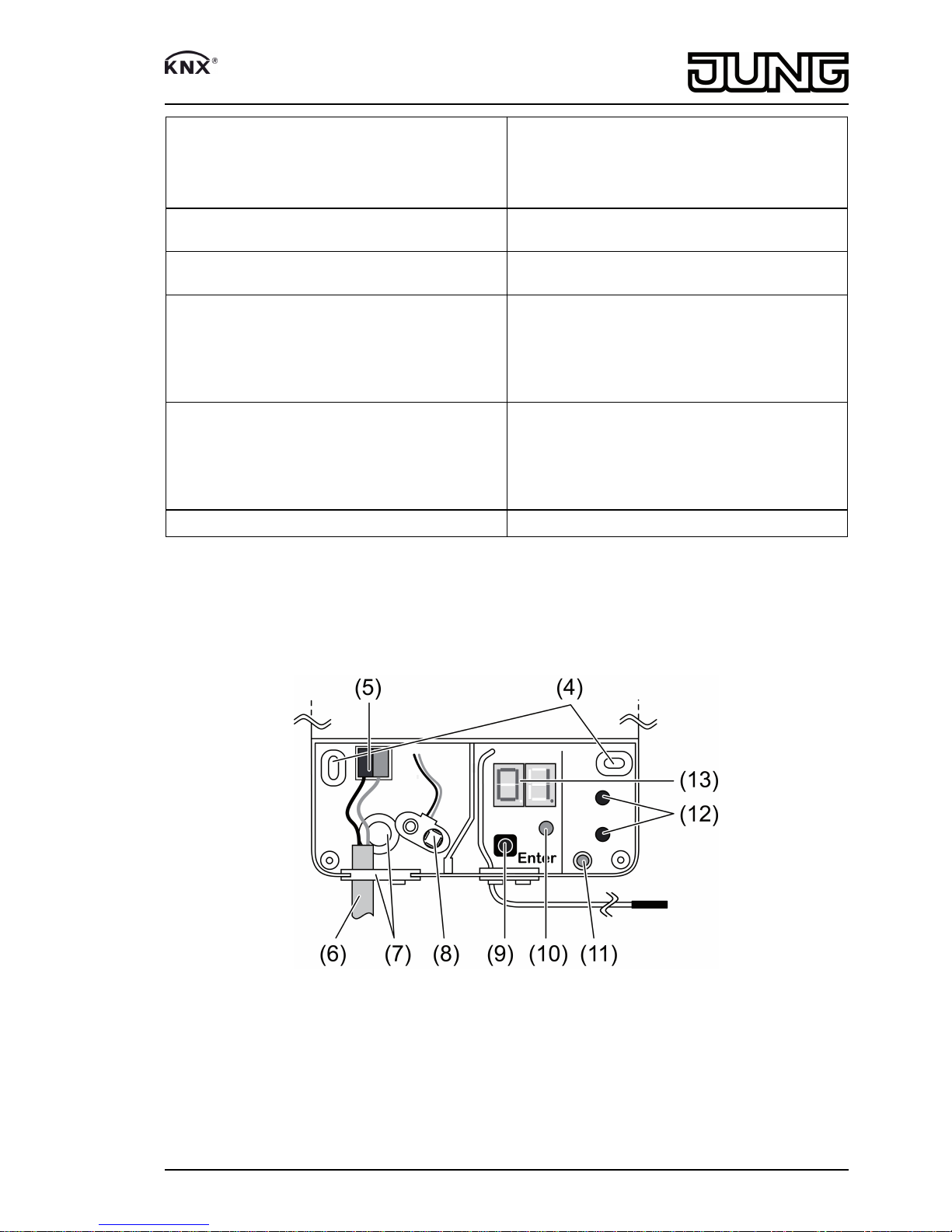
(10) Programming LED
(11) Programming button
(12) n / o buttons for selecting the radio channel
(13) Channel display
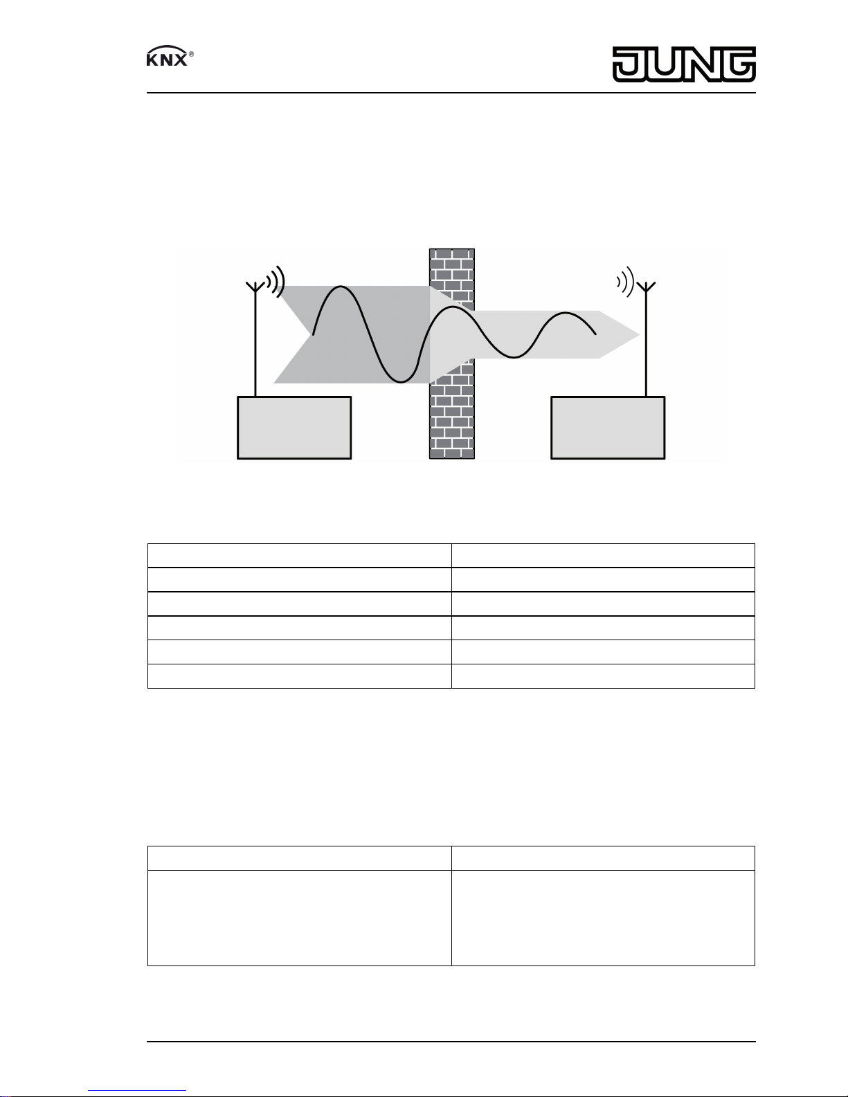
Maintain a distance of at least 0.5 m from metal surfaces and electrical devices, e.g. microwave
ovens, hi-fi and TV systems, electronic ballasts or transformers.
Maintain a distance of at least 1 m between transmitter and receiver in order to prevent
overmodulation of the receiver.
oSelect the mounting place so that the device will still be accessible for maintenance
purposes.
oInsert screws through the fastening holes (4) and screw devices to surface.
Connecting the device
oInsert bus cable (6) through one of the bushings (7) and connect to the device via terminal
(5).
iLay antenna (3) as far as possible from bus cable and other metallic parts. Do not roll up,
shorten, extend or strip the antenna.
4.2 Commissioning
iAssignment, transfer and deletion of radio transmitters requires a 9 V block battery.
Planning the configuration
For initial commissioning, especially with a view to later expandability, it is advisable to plan and
document the configuration in stages.
oRecord the desired state based on the following questions.
Question: Example:
Where will operation be performed? living room, office, hallway, entryway
What will be operated? ceiling lamp, wall lamp, Venetian blind, roller
shutter, exterior light, scene, All On/Off
How will operation be performed? switching, switching and dimming, short/long
operation of Venetian blind,
What will be used for operation? hand transmitter rocker switch No. 3 right/left,
motion detector, wall transmitter rocker switch
No. 1 top/bottom, universal transmitter, scene
button
iA radio transmitter can only be saved once.
iA radio channel can be operated from several radio transmitters.
iA radio transmitter can operate several more than one KNX device by linking them in the
KNX configuration with the same group address.
At the end of planning it must be known which channel will be operated via which radio
transmitter. Example:
Channel no. / application Device Radio transmitter
1 /
Switching, dimming
Living room ceiling lamp Hand transmitter,
rocker switch A / 1
2 /
Switching on, switching off
Ceiling fan Hand transmitter,
rocker switch C / 2
3 /
2 x switching
Switching 1: floor lamp
Switching 2: hallway lamp
Wall transmitter,
rocker switch 2
4/10
32532823
J0082532823 28.10.2016
Radio Management
Radio-KNX converter

4 /
Venetian blind
Bedroom roller shutters Wall transmitter,
rocker switch 3
5 /
Radio motion detector,
switching
Garage exterior light Radio motion detector
... ... ...
50 /
Switching
Cellar light 1gang wall transmitter
Wall transmitter,
rocker switch B / 1
oCreate necessary channels in KNX commissioning software.
oParameterise channels according to requirements.
oAssign group addresses according to KNX system.
Loading the physical address and application software
The device is connected and ready for operation.
The bus voltage is switched on.
oPress the Programming button (11).
The programming LED (10) lights up.
oAssign physical address.
The programming LED goes out.
oWrite the physical address on the device label.
oLoad the application software into the device.
Assigning the radio transmitter
Connection compartment is opened.
The application software is loaded into the device. The radio channels are configured.
iThe reception range is reduced during assignment. The distance between the receiver and
the radio transmitter is from 0.5 m to 5 m.
oConnect 9 V block battery to connection clip (8).
The channel display (13) lights up and indicates the current radio channel (figure 4).
Figure 4: Channel display lights up
oPress the both buttons n and o (12) for approx. 5 seconds. The right-hand decimal point
lights up additionally in the display (figure 5).
5/10
32532823
J0082532823 28.10.2016
Radio Management
Radio-KNX converter

Figure 5: Assignment mode
oUse the n / o buttons (12) to select the desired radio channel in accordance with the
planned and programmed configuration.
The display (13) shows the desired radio channel.
oTrigger a teach telegram on the desired radio transmitter (see instructions for radio
transmitter). Operate manually-operated transmitters until LE appears in the display
(figure 6).
Figure 6: Indication LE – „Learn“
oPress the Enter (9) button briefly.
The channel number flashes briefly in the display.
The radio transmitter has been saved.
iA channel can be operated from several radio transmitters.
iCancel operation: Press both buttons n and o (12) until the right-hand decimal point goes
out in the display.
iIf all 100 memory slots are occupies, the display shows OF (figure 7).
Figure 7: Indication OF – „Overflow“
Transferring radio transmitters
Connection compartment is opened.
oConnect 9 V block battery to connection clip (8).
The channel display (13) lights up (figure 4).
oPress both buttons n and o (12) for approx. 5 seconds.
6/10
32532823
J0082532823 28.10.2016
Radio Management
Radio-KNX converter

The right-hand decimal point lights up additionally in the display (figure 5).
oUse the n / o buttons (12) to select the desired new radio channel.
The display (13) shows the radio channel.
oTrigger a teach telegram on the desired radio transmitter (see instructions for radio
transmitter). Operate manually-operated transmitters until the still-current radio channel
flashes in the display.
oPress Enter button (9) for approx. 3 seconds.
The new channel number flashes briefly in the display.
The radio transmitter has been transferred.
iCancel operation: Press both buttons n and o (12) until the right-hand decimal point goes
out in the display.
Deleting individual radio transmitters of a radio channel
Connection compartment is opened.
oConnect 9 V block battery to connection clip (8).
The channel display (13) lights up (figure 4).
oPress both buttons n and o (12) for approx. 10 seconds.
The two decimal points light up additionally in the display (figure 8). Deletion mode is
active.
Figure 8: Deletion mode
oTrigger a teach telegram on the radio transmitter to be deleted (see instructions for radio
transmitter). Operate manually-operated transmitters until the desired radio channel
appears in the display (13).
The display (13) shows the radio channel that will be deleted.
oPress Enter button (9) for approx. 3 seconds.
The display (13) shows „- -“ (figure 9). The radio transmitter is deleted from the memory for
this radio channel.
The transmitter has been deleted as soon as the number of the radio channel appears
again in the display (13).
iCancel operation: Press one of the n or o buttons (12).
7/10
32532823
J0082532823 28.10.2016
Radio Management
Radio-KNX converter

Figure 9: Display „- - “ – deletion of a radio transmitter
Deleting all radio transmitters of a radio channel
Connection compartment is opened.
oConnect 9 V block battery to connection clip (8).
The channel display (13) lights up (figure 4).
oPress both buttons n and o (12) for approx. 10 seconds.
The two decimal points light up additionally in the display (figure 8). Deletion mode is
active.
oUse the n / o buttons (12) to select the desired radio channel in accordance with the
planned and programmed configuration.
The display (13) shows the radio channel that will be deleted.
oPress Enter button (9) for approx. 3 seconds.
CE (figure 10) appears on the display.
All radio transmitters for this radio channel have been deleted.
Figure 10: Indication CE – „Clear Entry“
Deleting all radio transmitters of all radio channels
Connection compartment is opened.
oConnect 9 V block battery to connection clip (8).
The channel display (13) lights up (figure 4).
oPress both buttons n and o (12) for approx. 10 seconds.
The two decimal points light up additionally in the display (figure 8). Deletion mode is
active.
oPress Enter button (9) for approx. 15 seconds.
AC (figure 11) appears on the display. All saved radio transmitters of all created radio
channels will be deleted.
When the deletion operation is complete, 00 appears on the display.
The device is in normal operating mode.
8/10
32532823
J0082532823 28.10.2016
Radio Management
Radio-KNX converter

Figure 11: Indication AC – „All Clear“
Complete commissioning
oRemove 9 V block battery.
oClosing the connection compartment.
oDocument saved radio transmitters.
5 Appendix
5.1 Technical data
KNX
KNX medium TP
Commissioning mode S-mode
Rated voltage KNX DC 21 ... 32VSELV
Power consumption KNX typ. 170mW
Connection mode KNX device connection terminal
Radio
Radio frequency 433.05MHz ... 434.79MHz
Receiver category 2
Teachable radio transmitter max. 100
Channel display supply
Battery type Alkaline 6LR 61
Power consumption approx. 140mW
Connection Battery clip
Ambient conditions
Ambient temperature -5 ... +45°C
Protection class III
Dimensions W×H×D 110×94×38 mm
5.2 Conformity
Albrecht Jung GmbH & Co. KG hereby declares that the radio system type
Art. No. 2700AP
corresponds to the directive 2014/53/EU. You can find the full article number on the device. The
complete text of the EU Declaration of Conformity is available under the Internet address:
www.jung.de/ce
5.3 Warranty
The warranty follows about the specialty store in between the legal framework as provided for
by law.
9/10
32532823
J0082532823 28.10.2016
Radio Management
Radio-KNX converter

ALBRECHT JUNG GMBH & CO. KG
Volmestraße 1
58579 Schalksmühle
GERMANY
Telefon: +49 2355 806-0
Telefax: +49 2355 806-204
www.jung.de
10/10
32532823
J0082532823 28.10.2016
Radio Management
Radio-KNX converter
Table of contents
Other Jung Media Converter manuals
Popular Media Converter manuals by other brands

FLIR
FLIR Raymarine E22158 installation instructions

Balluff
Balluff BAE SA-FF-055-RS quick start guide

SystemBase
SystemBase SWIFIALLV10 user manual

Z3 Technology
Z3 Technology Z3-MVE-20 User instructions

Cross Technologies
Cross Technologies 2016-75-213 instruction manual

SMAR
SMAR IF302 Operation, maintenance & instruction manual