Aquaread BlackBox User manual

Instruction Manual
for the
Aquaread BlackBoxTM
Multiparameter Water Quality
Data Converter
Software revision 2.00 and above)
Revision: P
Date: September 10th 2019
Aquaread Ltd
Bridge House
Northdown Industrial Park
Broadstairs
Kent
CT10 3JP
ENGL ND
Phone: +44 1843 600 030
www.aquaread.com

quaread BlackBox™ Instruction Manual
10401-00618 Rev P
PROPRIETARY NOTICE
The information disclosed within this document or separately supplied in furtherance of this
document includes proprietary rights of Aquaread Ltd. Neither this document nor the
information disclosed herein or of a supplementary nature shall be reproduced or transferred
to other documents or used for any other purposes, except as specifically authorised in
writing by Aquaread Ltd. Copyright 2 19 Aquaread Ltd. All rights reserved.
SOFTWARE LICENCE AGREEMENT
By using the BlackB x, its ass ciated pr bes and meter, y u agree t be b und by
the terms and c nditi ns f the f ll wing s ftware licence agreement. Please read
this agreement carefully.
Aquaread Ltd grants you a limited license to use the software embedded in the devices (the “Software”) in
binary executable form in the normal operation of the products. Title, ownership rights and intellectual
property rights in and to the Software remain in Aquaread Ltd.
You acknowledge that the Software is the property of Aquaread Ltd and is protected under British copyright
laws and international copyright treaties. You further acknowledge that the structure, organisation and code
of the Software are valuable trade secrets of Aquaread Ltd.
You agree not to decompile, dissemble, modify, reverse assemble, reverse engineer or reduce to human
readable form the Software or any part thereof or create any derivative works based on the Software.
RECYCLING
Any product bearing this symbol must be handed over to an applicable collection point for the
recycling of electrical and electronic equipment. By ensuring this product is disposed of properly,
you will prevent possible adverse consequences for the environment which could be caused by
inappropriate waste handling.
Note: For return for recycling, please contact Aquaread Ltd for instructions on how to return end-of-life
equipment, accessories, and all auxiliary items for proper disposal.
WARNING
Favourable indications made by this equipment d n t guarantee water is safe for human
or animal consumption. This equipment can n t detect the presence of harmful bacteria or
toxins. If in doubt, ALWAYS TREAT SUSPECT WATER PRIOR TO CONSUMPTION. In
n event will Aquaread Ltd be liable f r any incidental, special, indirect r
c nsequential damages, whether resulting fr m the use, misuse, miscalibrati n r
inability t use this equipment, r fr m defects in the equipment.
TRADEMARKS
Aquaread®, Aquameter® and Aquaprobe®
are all trademarks of Aquaread® Ltd.
© 2019 quaread Ltd. www.aquaread.com Page 2 of 71

quaread BlackBox™ Instruction Manual
10401-00618 Rev P
Table f C ntents
1. INTRODUCTION............................................................................................................................................................5
1.1. WHAT DOES IT DO?.........................................................................................................................................................5
1.2. THE BLACKBOX AND THE ENVIRONMENT...........................................................................................................................5
2. WIRING OVERVIEW....................................................................................................................................................6
2.1. IMPORTANT INFORMATION REGARDING THE POWER SUPPLY..................................................................................................6
2.2. THE MULTICORE CORE CABLE.........................................................................................................................................6
2.3. SDI 12 / MODBUS SELECTION.........................................................................................................................................6
2.4. SLEEP MODE WHEN CONFIGURED FOR MODBUS OUTPUT.....................................................................................................6
2.5. SLEEP MODE WHEN CONFIGURED FOR SDI 12 OUTPUT.....................................................................................................7
3. APPLICATION WIRING DIAGRAMS........................................................................................................................8
3.1. SDI 12 DIGITAL INTERFACE (ALWAYS ON)........................................................................................................................8
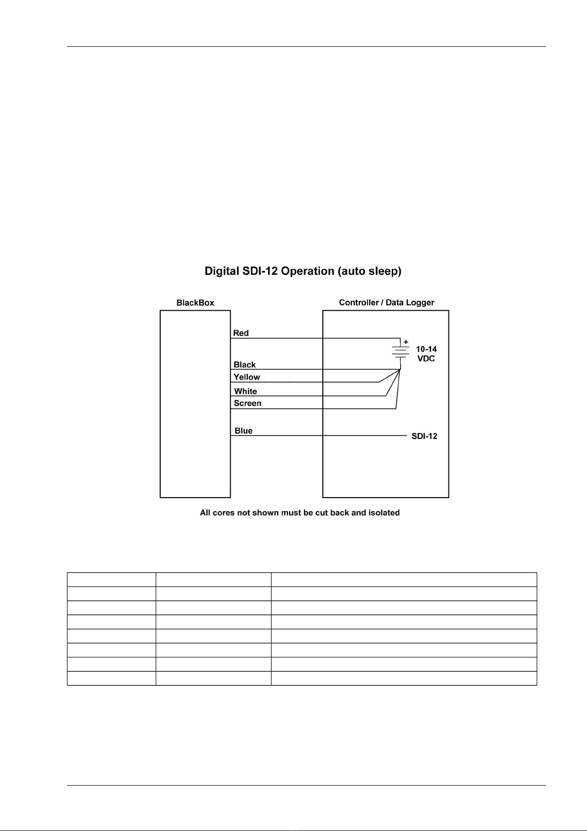
3.2. SDI 12 DIGITAL INTERFACE (AUTO SLEEP)........................................................................................................................9
3.3. SDI 12 DIGITAL INTERFACE WITH SELF POWERED TELEMETRY AND EXTERNAL POWER........................................................10
3.4. MODBUS MASTER DIGITAL INTERFACE............................................................................................................................11
3.5. 4 20MA CURRENT LOOPS.............................................................................................................................................12
4. INSTALLATION...........................................................................................................................................................14
4.1. CALIBRATING THE AQUAPROBE.......................................................................................................................................14
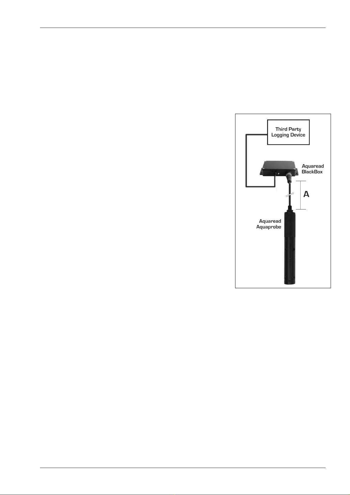
4.2. CONNECTING THE AQUAPROBE........................................................................................................................................14
4.3. IMPORTANT INFORMATION REGARDING DEPTH MEASUREMENT............................................................................................14
4.4. NORMAL OPERATION.....................................................................................................................................................14
4.5. LED INDICATIONS........................................................................................................................................................15
5. TROUBLESHOOTING.................................................................................................................................................15
6. DECLARATION OF CONFORMITY........................................................................................................................16
7. TECHNICAL SPECIFICATION.................................................................................................................................16
8. SDI 12 DATA COMMUNICATION PROTOCOL....................................................................................................17
8.1. DATA PACKET FORMATS................................................................................................................................................17
8.1.1. Acknowledge Active..........................................................................................................................................17
8.1.2. Address Query..................................................................................................................................................17
8.1.3. Change Address................................................................................................................................................18
8.1.4. Send Identi ication............................................................................................................................................18
8.1.5. Start Measurement...........................................................................................................................................18
8.1.6. Additional Measurements.................................................................................................................................18
8.1.7. Start Measurement and Request CRC..............................................................................................................19
8.1.8. Additional Measurements and Request CRC...................................................................................................19
8.1.9. Start Concurrent Measurement........................................................................................................................19
8.1.10. Additional Concurrent Measurements...........................................................................................................19
8.1.11. Start Concurrent Measurement and Request CRC.........................................................................................20
8.1.12. Additional Concurrent Measurements and Request CRC..............................................................................20
8.1.13. Start Veri ication............................................................................................................................................20
8.1.14. Service Request...............................................................................................................................................20
8.1.15. Send Data.......................................................................................................................................................21
8.1.16. Continuous Measurements.............................................................................................................................21
8.1.17. Continuous Measurements and Request CRC................................................................................................21
8.2. BLACKBOX ADDRESS....................................................................................................................................................21
8.3. UNIT IDENTIFICATION....................................................................................................................................................22
8.4. MEASUREMENT COMMANDS...........................................................................................................................................22
8.4.1. AP-100..............................................................................................................................................................24
8.4.2. AP-100 with Depth...........................................................................................................................................26
8.4.3. AP-200..............................................................................................................................................................27
8.4.4. AP-200 with Depth...........................................................................................................................................28
© 2019 quaread Ltd. www.aquaread.com Page 3 of 71

quaread BlackBox™ Instruction Manual
10401-00618 Rev P
8.4.5. AP-300..............................................................................................................................................................29
8.4.6. AP-300 with Depth...........................................................................................................................................31
8.4.7. AP-400..............................................................................................................................................................33
8.4.8. AP-400 with Probe...........................................................................................................................................34
8.4.9. AP-500..............................................................................................................................................................35
8.4.10. AP-500 with Probe.........................................................................................................................................37
8.4.11. AP-600............................................................................................................................................................39
8.4.12. AP-600 with Depth.........................................................................................................................................41
8.4.13. AP-700............................................................................................................................................................43
8.4.14. AP-700 with Depth.........................................................................................................................................45
8.4.15. AP-800(so tware version 3.53 and below) and AP-900.................................................................................47
8.4.16. AP-800 with Depth (so tware version 3.53 and below), AP-900 with Depth & AP-1000.............................49
8.4.17. AquaPlus Probe..............................................................................................................................................51
8.4.18. AP-2000 and AP-700/800 (so tware version 4.00 and above).......................................................................53
8.4.19. AP-2000 with Depth and AP-700/800 with Depth (so tware version 4.00 and above).................................55
8.4.20. AP- Lite...........................................................................................................................................................57
8.4.21. AP-5000..........................................................................................................................................................58
8.4.22. AP-7000..........................................................................................................................................................60
8.4.23. Important note concerning AP-7000 sel cleaning.........................................................................................61
8.5. VERIFICATION COMMAND...............................................................................................................................................62
8.6. CYCLIC REDUNDANCY CHECK........................................................................................................................................62
9. MODBUS COMMUNICATION PROTOCOL...........................................................................................................63
9.1. ELECTRICAL INTERFACE.................................................................................................................................................63
9.2. DATA FRAME FORMAT..................................................................................................................................................63
9.3. COMMUNICATION SEQUENCE & TIMING...........................................................................................................................63
9.4. DATA PACKET FORMAT.................................................................................................................................................64
9.4.1. Exception Responses........................................................................................................................................64
9.4.2. Read Holding Registers....................................................................................................................................65
9.4.3. Read Input Registers........................................................................................................................................65
9.4.4. Write Holding Register.....................................................................................................................................66
9.4.5. Write Holding Registers...................................................................................................................................66
9.4.6. Report Slave ID................................................................................................................................................67
9.5. REGISTER MAP.............................................................................................................................................................67
9.5.1. Slave Address...................................................................................................................................................70
9.5.2. Serial Communication Speed...........................................................................................................................70
9.5.3. Serial Communication Parity...........................................................................................................................70
9.5.4. Input Registers..................................................................................................................................................70
9.6. CYCLIC REDUNDANCY CHECK........................................................................................................................................70
9.7. IMPORTANT NOTE CONCERNING AP 7000 SELF CLEANING...................................................................................................71
© 2019 quaread Ltd. www.aquaread.com Page 4 of 71

quaread BlackBox™ Instruction Manual
10401-00618 Rev P
1. Intr ducti n
This manual covers the setup, operation and maintenance of the Aquaread BlackBox at
software revision 2. and above, and should be read in conjunction with the latest revision
of the relevant Aquaread Aquaprobe Instruction Manual. If y ur BlackB x is running
earlier s ftware, the utput pr t c ls may be different fr m th se sh wn in this
manual. In this case, c ntact Aquaread f r an earlier versi n f this manual r return
y ur BlackB x f r s ftware upgrade (chargeable).
1.1. What d es it d ?
The Aquaread BlackBox is a data converter that allows any
model of Aquaread water quality probe (Aquaprobe) to be
interfaced directly to a third party processing, control or
logging device. The distance ‘A’ between the BlackBox and
the Aquaprobe can be up to 1 meters.
With a choice of industry standard digital interfaces and two
analogue channels, the BlackBox offers a versatile and cost
effective data collection solution utilising any of the
advanced range of Aquaread multiparameter Aquaprobes.
The BlackBox features an integral barometric pressure
sensor for automatic depth and DO correction and can
output up to thirty-three water parameters plus barometric
pressure on an SDI-12 or Modbus (RS485) Digital Interface.
In addition, any two parameters can be chosen for output on
the two independent 4 - 2 mA analogue channels. Data is
refreshed every two seconds.
Low current consumption and a rugged aluminium case
make the BlackBox particularly suitable for long term
unattended deployment.
For applications where water quality data needs to be collected remotely, the BlackBox is
again the answer. In this configuration, logging device is replaced by a third party telemetry
device that can transmit data to a remote monitoring station anywhere in the world.
1.2. The BlackB x and the Envir nment
The BlackBox is designed to be used outdoors and is rated to IP67, that is to say it is
waterproof but it is n t designed for submersion. Depth and Dissolved Oxygen
measurements rely on the ability of the BlackBox to read atmospheric pressure. If the unit
is submerged, the depth measurement feature will not work and the Dissolved Oxygen
readings will be erroneous.
Please n te that the s cket n the BlackB x is nly waterpr f when the ass ciated
Aquapr be plug is fitted. With ut the plug fitted, water can enter the s cket. Damage
caused t the s cket by water ingress is n t c vered by y ur warranty.
You may notice a small hole on the side of the unit. This is a waterproof vent for the internal
barometric sensor. D n t p ke anything in this h le! Doing so will cause major damage
to the vent’s waterproof membrane and invalidate your warranty.
© 2019 quaread Ltd. www.aquaread.com Page 5 of 71

quaread BlackBox™ Instruction Manual
10401-00618 Rev P
2. Wiring Overview
The BlackBox is supplied with a screened multicore cable for connection to a variety of
third party controller devices. This 6 core cable provides power in to the BlackBox and
serial data out. If you have chosen to order a unit with the optional analogue channels, the
BlackBox will be supplied with a 1 core cable.
Any cable c res that are n t being used MUST be trimmed back and insulated fr m ne-
an ther, the p wer supply and gr und. The screen ( r shield) f the cable sh uld be
c nnected t chassis gr und at the c ntr ller.
2.1. Imp rtant Inf rmati n Regarding the P wer Supply
If the Aquaprobe you are attaching to the BlackBox includes a depth measurement sensor
(AP-7 -D, AP-8 -D, AP-2 -D, AP-5 or AP-7 ), power must be left applied to
the BlackBox at all times. See section 4.3 Important Information Regarding Depth
Measurement. If power saving is required, the white core (On/Off switch line) should be
used to put the BlackBox to sleep.
If you are installing an AP-7 with the BlackBox, power must be left applied to the
BlackBox at all times. See section 8.4.23 Important note concerning AP-7 self cleaning.
2.2. The Multic re C re Cable
The table below gives an overview of the cable core designations for the six/ten-core
power/data cable. If you have not requested activation of the analogue channels, your
BlackBox will be fitted with a six core cable. Please refer to the individual application wiring
diagrams in the next section before making any connections.
Six / Ten C re Cable
C re C l ur Designati n Functi n
Red Power supply +ve 1 V – 14V DC +ve power supply input
Black Power supply –ve Power supply ground
Blue RS485 - / SDI-12 RS485 – (B) (Modbus) or SDI-12 I/O
Green RS485 + RS485 + (A) (Modbus) I/O
White On/Off switch line Power control line (sleep mode)
Yellow SDI-12 / Modbus SDI-12 / Modbus select line
Brown 4 - 2 mA Loop 1 Optional Analogue current loop 1 supply
Violet 4 - 2 mA Loop 1 Optional Analogue current loop 1 return
Orange 4 - 2 mA Loop 2 Optional Analogue current loop 2 supply
Pink 4 - 2 mA Loop 2 Optional Analogue current loop 2 return
2.3. SDI-12 / M dbus Selecti n
The yellow core is used to select between SDI-12 or Modbus (RS485) serial data
communications. Tying the yellow core to the +ve power supply will configure the digital
output as Modbus (RS485). Tying the yellow core to ground will configure the digital output
as SDI-12. Please note: the yellow core must not be left floating.
2.4. Sleep M de When C nfigured f r M dbus Output
The white core can be used to put the BlackBox into a low power sleep mode. If the white
core is taken to a voltage above 6V, the BlackBox will run continuously and readings will be
refreshed every 2 seconds. If the white core is taken to ground, the BlackBox will enter
sleep mode.
© 2019 quaread Ltd. www.aquaread.com Page 6 of 71

quaread BlackBox™ Instruction Manual
10401-00618 Rev P
When the white core is subsequently taken above 6V, the BlackBox will wake-up and re-
enter normal running mode but the data utputs will n t be stable and valid f r 40
sec nds.
If an AP-7 is connected, the data outputs will not be stable and valid until 60 sec nds
after wake-up.
2.5. Sleep M de When C nfigured f r SDI-12 Output
When configured for SDI-12 output, sleep mode can be configured to work automatically. If
the white core is tied permanently to ground, the BlackBox will stay in sleep mode unless
woken up by a ‘measurement request’ on the SDI-12 line. As soon as the data is ready to
be sent (usually after 4 seconds), the BlackBox will issue a ‘service request’ to the
controller. Once the controller has read the data, the BlackBox will automatically re-enter
sleep mode.
If the BlackBox is running software revision 2. 5 or below and an AP-7 is connected, a
self clean command will be sent to the Probe each time it is woken up. This will add a
further 2 seconds to the time taken for the readings to be ready.
If the BlackBox is running software revision 3. and above and an AP-7 is connected,
a self clean command is not sent on each wake-up. Software revision 3. and above
sends a self clean command every six hours, regardless of the mode selected. For this
reason, it is very important that power is left applied to the BlackBox at all times.
If an AP-7 is connected, see section 8.4.23 Important note concerning AP-7 self
cleaning.
Please also refer to section 2.1 Important Information Regarding the Power Supply.
© 2019 quaread Ltd. www.aquaread.com Page 7 of 71

quaread BlackBox™ Instruction Manual
10401-00618 Rev P
3. Applicati n Wiring Diagrams
3.1. SDI-12 Digital Interface (always n)
In this configuration, the BlackBox is permanently on and SDI-12 data is instantly available
on request. See section 8 for details of the SDI-12 data communication protocol.
Six C re Cable Usage
C re C l ur Designati n C nnecti n
Red Power supply +ve 1 V – 14V DC +ve power supply input
Black Power supply –ve Power supply ground
Blue SDI-12 Controller SDI-12 I/O line
Green RS485 + Must be isolated and left floating
White On/Off switch line +ve power supply input
Yellow SDI-12 / Modbus Power supply ground
Screen Screen / Shield Power supply or chassis ground
In this c nfigurati n, p wer sh uld be left n the BlackB x c ntinu usly.
If the controller has a switched output to control external devices, this can be connected to
the white core (on/off switch line) and can be pulled to ground to put the BlackBox into
sleep mode if power saving is required.
Please n te: the white c re must n t be left fl ating.
If an AP-7 is connected, see section 8.4.23 Important note concerning AP-7 self
cleaning.
© 2019 quaread Ltd. www.aquaread.com Page 8 of 71

quaread BlackBox™ Instruction Manual
10401-00618 Rev P
3.2. SDI-12 Digital Interface (aut sleep)
In this configuration, the BlackBox is usually in power saving (sleep) mode. Requests for
data on the SDI-12 bus will wake the BlackBox up and there will be a delay of up to 4
seconds before data is ready.
If the BlackBox is running software revision 2. 5 or below and an AP-7 is connected, a
self clean command will be sent to the Probe each time it is woken up. This will add a
further 2 seconds to the time taken for the readings to stabilise.
As soon as the data is ready to be sent, the BlackBox will issue a ‘service request’ to the
controller. Once the controller has read the data, the BlackBox will automatically re-enter
sleep mode. See section 8 for details of the SDI-12 data communication protocol.
Six C re Cable Usage
C re C l ur Designati n C nnecti n
Red Power supply +ve 1 V – 14V DC +ve power supply input
Black Power supply –ve Power supply ground
Blue SDI-12 Controller SDI-12 I/O line
Green RS485 + Must be isolated and left floating
White On/Off switch line Power supply ground
Yellow SDI-12 / Modbus Power supply ground
Screen Screen / Shield Power supply or chassis ground
Please refer to section 2.1 Important Information Regarding the Power Supply.
If an AP-7 is connected, see section 8.4.23 Important note concerning AP-7 self
cleaning.
© 2019 quaread Ltd. www.aquaread.com Page 9 of 71

quaread BlackBox™ Instruction Manual
10401-00618 Rev P
3.3. SDI-12 Digital Interface with Self P wered Telemetry and External P wer
In this configuration, the telemetry or logging device connected to the BlackBox is self
powered from internal batteries but the BlackBox and Aquaprobe are powered from an
external battery, which can have a solar panel attached if required in order to maintain
charge.
The BlackBox is usually in power saving (sleep) mode. Requests for data on the SDI-12
bus will wake the BlackBox up and there will be a delay of up to 4 seconds (6 seconds
for an AP-7 ) before data is ready. During this time power will be drawn from the
external battery. After the reading, the BlackBox will re-enter sleep mode.
If the optional solar panel is to be used, the 12V battery should be sized at ~6Ah. If the
solar panel is not going to be included, a larger 12V battery (such as a car or caravan
battery) will be required, dependant upon the sampling rate and the proposed re-charge
interval.
If an AP-7 is connected, see section 8.4.23 Important note concerning AP-7 self
cleaning.
© 2019 quaread Ltd. www.aquaread.com Page 10 of 71

quaread BlackBox™ Instruction Manual
10401-00618 Rev P
3.4. M dbus Master Digital Interface
In this configuration, the BlackBox is permanently on and Modbus data is instantly available
on request. See section 9 for details of the Modbus data communication protocol.
Six C re Cable Usage
C re C l ur Designati n C nnecti n
Red Power supply +ve 1 V – 14V DC +ve power supply input
Black Power supply –ve Power supply ground
Blue RS485 (-/B) Controller RS485 (- or B) line
Green RS485 (+/A) Controller RS485 (+ or A) line
White On/Off switch line +ve power supply input
Yellow SDI-12 / Modbus +ve power supply input
Screen Screen / Shield Power supply or chassis ground
Please refer to section 2.1 Important Information Regarding the Power Supply.
If the controller has a switched output to control external devices, this can be connected to
the white core (on/off switch line) and can be pulled to ground to put the BlackBox into
sleep mode if power saving is required.
If the BlackBox is put into sleep mode, then the white core is subsequently taken above 6V,
the BlackBox will re-enter normal running mode but the data will n t be stable and valid
f r 40 sec nds.
If an AP-7 is connected, the data outputs will not be stable and valid for up to 60
sec nds after leaving sleep mode. See 9.7 Important note concerning AP-7 self
cleaning.
© 2019 quaread Ltd. www.aquaread.com Page 11 of 71

quaread BlackBox™ Instruction Manual
10401-00618 Rev P
3.5. 4-20mA Current L ps
The two optional 4-2 mA current loops are factory programmable only. The required
outputs from the two current loops should have been specified at the time of ordering. If this
was done, your BlackBox will have been supplied with a ten core cable and the analogue
outputs will conform to your requested parameters and ranges.
In the configuration shown above, the BlackBox is permanently on and the current loops
are permanently active. SDI-12 digital operation is also selected (yellow core).
Ten C re Cable Usage
C re C l ur Designati n Functi n
Red Power supply +ve 1 V – 14V DC +ve power supply input (see note 2)
Black Power supply –ve Power supply ground
Blue RS485 - / SDI-12 RS485 – (B) (Modbus) or SDI-12 I/O
Green RS485 + RS485 + (A) (Modbus) I/O
White On/Off switch line Power control line (see note 3)
Yellow SDI-12 / Modbus SDI-12 / Modbus select line (see previous sections)
Brown 4 - 2 mA Loop 1 Analogue current loop 1 supply (see note 1)
Violet 4 - 2 mA Loop 1 Analogue current loop 1 return (see note 1)
Orange 4 - 2 mA Loop 2 Analogue current loop 2 supply (see note 1)
Pink 4 - 2 mA Loop 2 Analogue current loop 2 return (see note 1)
© 2019 quaread Ltd. www.aquaread.com Page 12 of 71

quaread BlackBox™ Instruction Manual
10401-00618 Rev P
N te 1: The two 4-2 mA current loop outputs are completely isolated from each other and
from the rest of the BlackBox circuitry. Whilst the cores assigned to the two current loops
are designated as supply and return respectively, they are, in fact, bi-polar and can be
connected either way round.
N te 2: the BlackBox must have its normal power supply connected and the on/off switch
line (white core) taken high in order for the current loop outputs to work. The current loop
outputs operate independently from the digital output which can be used simultaneously if
required.
N te 3: In this configuration, power should be left on the BlackBox continuously.
If the controller has a switched output to control external devices, this can be connected to
the white core (on/off switch line) and can be pulled to ground to put the BlackBox into
sleep mode if power saving is required.
If the BlackBox is put into sleep mode, then the white core is subsequently taken above 6V,
the BlackBox will re-enter normal running mode but the 4-20mA l ps will n t be stable
and valid f r 40 sec nds.
If an AP-7 is connected, the 4-20mA l ps will n t be stable and valid f r 60
sec nds after leaving sleep mode.
If the BlackBox is running software revision 2. 5 or below and an AP-7 is connected, a
self clean command will be sent to the Probe each time it is woken up.
If the BlackBox is running software revision 3. and above and an AP-7 is connected,
a self clean command is not sent on each wake-up. Software revision 3. and above
sends a self clean command every six hours, regardless of the mode selected. For this
reason, power should be left applied to the BlackBox at all times. If a low power mode is
required between readings, use the on/off (sleep) line.
Please refer to section 2.1 Important Information Regarding the Power Supply.
© 2019 quaread Ltd. www.aquaread.com Page 13 of 71

quaread BlackBox™ Instruction Manual
10401-00618 Rev P
4. Installati n
The BlackBox features an aluminium flange with four 5mm (3/16”) mounting holes. The unit
should be fixed using these mounting holes in a sheltered position where it can not become
submerged in water.
4.1. Calibrating the Aquapr be
Prior to use, the selected Aquaprobe should be fully calibrated using an Aquaread
Aquameter or an AP-PC Kit and a set of calibration standards. See the latest revision of the
relevant Aquaprobe Instruction Manual for calibration procedures.
4.2. C nnecting the Aquapr be
With the power switched off, the selected Aquaprobe should be plugged into the socket on
the BlackBox. When the power is switched on, the bi-colour LED should light continuously
in yellow for two seconds to indicate the probe has been successfully recognised and
initialised. If the LED flashes red, this means there is a problem. Refer to section 4.5 LED
Indications for more information.
4.3. Imp rtant Inf rmati n Regarding Depth Measurement
Depth is measured in the Aquaprobe by a pressure sensor mounted inside the body of the
probe. The depth measurement reference point on the Aquaprobe is the top row of holes in
the sleeve. Depth is calculated by subtracting the barometric pressure being measured in
the BlackBox from the water pressure being measured in the Aquaprobe. The pressure
differential, once corrected for temperature and salinity (water density), is directly
proportional to depth.
The depth measurement system uses the EC sensor to detect when the probe has been
placed in water. All the time the probe is measuring an EC of zero, the depth will read zero
and the depth zero datum will be kept updated.
For this reason, it is important to ensure the Aquaprobe is connected to the BlackBox,
power is applied and the BlackBox has been awake and has taken readings (LED flashing
yellow) bef re the Aquapr be is l wered int the water. It is also important that power is
left applied to the BlackBox at all times or the depth zero datum will be lost.
Please also refer to section 2.1 Important Information Regarding the Power Supply.
4.4. N rmal Operati n
Directly after the application of power, the BlackBox will light the bi-colour LED yellow for
two seconds then proceed to take readings at two-second intervals. Each time a reading is
taken, the LED will give a single, short yellow flash. Each time the BlackBox communicates
with the controlling device, the LED in the BlackBox will light up yellow for ½ a second.
So, during normal operation, you should see the LED give a brief yellow flash every two
seconds and a longer yellow flash periodically, depending on the sample rate set up in the
controller.
If the BlackBox is configured in ‘auto sleep’ mode, readings will be taken for 4 seconds
from power-up before the unit enters sleep mode. During this initial power-up period, the
Aquaprobe should be ut f the water in order to establish the depth zero datum.
When in sleep mode, the LED will not flash.
© 2019 quaread Ltd. www.aquaread.com Page 14 of 71

quaread BlackBox™ Instruction Manual
10401-00618 Rev P
4.5. LED Indicati ns
The BlackBox has a single, bi-colour LED positioned next to the probe socket. This LED is
used to indicate the status of the BlackBox by flashing at various rates in either red or
yellow. The chart below shows the possible combinations and what they mean.
Sequence What it means Acti n
Short yellow flash
every 2 seconds
The BlackBox has just communicated
with the Aquaprobe.
Normal operation. No action
required
Long yellow flash The BlackBox has just communicated
with the controller device.
Normal operation. No action
required
Single red flash
every two seconds BlackBox can not read the Aquaprobe. See Troubleshooting below
Two short red
flashes every 2
seconds
The Aquaprobe’s pH electrode requires
servicing or calibration.
See Troubleshooting below and the
Aquaprobe manual.
Three short red
flashes every 2
seconds
The probe’s optical DO electrode
requires servicing or calibration
See Troubleshooting below and the
Aquaprobe manual.
If a probe error condition occurs, the short yellow flash that indicates probe communication
will be replaced by one of the three red flashing sequences.
5. TROUBLESHOOTING
This section details some of the common difficulties you may encounter when using the
BlackBox. Try all the suggested remedies. If your problem is still unresolved, contact our
Service Department.
Pr blem Cause / Remedy
The BlackBox LED does
not flash at all.
The unit may be in auto-sleep mode.
Power supply problem. Check all connections.
The white power control wire may be grounded causing the
unit to be permanently asleep.
The internal fuse may be blown. Remove lid and check fuse.
The BlackBox LED gives
a single red flash even
when the Aquaprobe is
connected.
Probably a poor connection. Disconnect the Aquaprobe plug,
ensure there is no debris or moisture in the plug and socket,
then re-connect the plug ensuring it is fully inserted and that
the screw collar is fully tightened.
The BlackBox LED gives
a double red flash every
two seconds.
This means the pH electrode fitted to the probe has dropped
below 85% efficiency. Try cleaning the pH electrode and re-
calibrating as described in the relevant section of the
Aquaprobe manual. If that does not cure the problem, replace
the pH/ORP electrode.
The BlackBox LED gives
a triple red flash every
two seconds.
This means the Optical DO electrode on the Aquaprobe
needs calibrating or the cap needs replacing. Perform a full
DO calibration, first at DO Zero then at 1 % DO as
described in the relevant section of the Aquaprobe manual. If
that does not cure the problem, replace the Optical DO Cap.
No output on the 4-2 mA
current loops.
Current loops do not become live until 4 seconds after
power on or wake-up.
BlackBox not reading the Aquaprobe. Check LED indications.
© 2019 quaread Ltd. www.aquaread.com Page 15 of 71

quaread BlackBox™ Instruction Manual
10401-00618 Rev P
6. DECLARATION OF CONFORMITY
The manufacturer declares that the equipment described herein is in compliance with the
essential requirements and other relevant provisions of Directives 2 4/1 8/EC and
1999/5/EC.
7. Technical Specificati n
Input Voltage 1 V – 14V DC
Operating Temperature -5ºC – 5 ºC
Input Current*
(awake)
~ 4 mA (AP-Lite / AquaPlus / AP-7 - AP-2 attached)
~ 8 mA (AP-5 or AP-7 attached)
~ 3 mA (AP-7 during self cleaning cycle)
Input Current
(asleep) < 5 µA
Protection Class IP67 (must not be submerged due to barometric pressure sensor)
Dimensions 14 mm x 65mm x 3 mm (5.5” x 2.6” x 1.2”)
Weight 4 g (14oz)
Connections Probe socket & 1M screened power/data cable
Fixing Aluminium flange with four 5mm (3/16”) mounting holes
Digital Interface User selectable between SDI-12 and Modbus (RS485)
Update rate All data is refreshed every 2 seconds when not in sleep mode
Current Loop Accuracy +/- .2mA (represents +/-1.25% of FS digital value)
*Input currents are shown as approximate because current consumption varies with the
number and type of optional electrodes fitted to the Aquaprobe.
Aquaread reserves the right to alter specifications without notice.
© 2019 quaread Ltd. www.aquaread.com Page 16 of 71

quaread BlackBox™ Instruction Manual
10401-00618 Rev P
8. SDI-12 Data C mmunicati n Pr t c l
SDI-12 is a standard for interfacing data recorders with microprocessor-based sensors.
SDI-12 stands for serial/digital interface at 12 baud. This section describes the protocol
for communications between the BlackBox and SDI-12 data recorders complying with
Version 1.3 of the SDI-12 standard.
8.1. Data Packet F rmats
The BlackBox responds to commands sent to it by an SDI-12 data recorder. Command
packets should have the format:
<a><command-data>!
where:
<a> is the BlackBox address character (valid values are ASCII “ ”-”9”, “A”-”Z”,
“a”-”z” & “?”)
<command-data> is a string of zero or more command dependent data characters
(values in the range x2 - x7E, excluding x21 (ASCII “!”))
the packet is terminated by x21 (ASCII “!”)
Response packets have the format:
<a><response-data>[<crc>]<CR><LF>
where:
<a> is the BlackBox's address character
<response-data> is a string of zero or more command dependent data characters
(values in the range x2 - x7E)
<crc>, when present, is a string of 3 characters encoding the cyclic redundancy
check of the response data (1st character in the range x4 - x4F, 2nd & 3rd
characters in the range x4 - x7F)
the packet is terminated by a carriage return followed by a line feed
The formats of the individual command/response packets that the BlackBox supports are
described in the following subsections. Any measurement values that are invalid will be
returned with all fields set to 9.
8.1.1. Ackn wledge Active
This command allows the data recorder to check that the BlackBox is present on the SDI-
12 bus.
Command Response
<a>! <a><CR><LF>
8.1.2. Address Query
This command allows the data recorder to obtain a sensor's address character. It must only
be issued when there is just one sensor attached to the bus, otherwise all sensors will
respond, causing bus contention.
Command Response
?! <a><CR><LF>
© 2019 quaread Ltd. www.aquaread.com Page 17 of 71

quaread BlackBox™ Instruction Manual
10401-00618 Rev P
8.1.3. Change Address
This command allows the data recorder to assign a new address to the BlackBox.
Command Response
<a>A<b>! <b><CR><LF>
<b> is a new address to be assigned to the unit (1 character, value “ ”-”9”, “A”-”Z”
or “a”-”z”)
8.1.4. Send Identificati n
This command allows the data recorder to retrieve some basic information about the
BlackBox and the Aquaprobe attached to it.
Command Response
<a>I! <a><sdi-ver><vendor-id><model-nr><firmware-ver><serial-nr>
<CR><LF>
<sdi-ver> is the version of the supported SDI-12 standard (“13” for version 1.3)
<vendor-id> is an 8-character vendor identification string (“AQUAREAD”)
<model-nr> is a 6-character Aquaprobe model string (e.g. “AP1 ”)
<firmware-ver> is the 3-digit Probe's firmware version string (e.g. “1 ” for v1. )
<serial-nr> is the Probe's serial number string (may be up to 13 characters)
8.1.5. Start Measurement
This command tells the BlackBox to start making a measurement.
Command Response
<a>M! <a><time><nr-val es><CR><LF>
<time> is the time in seconds (three digits) until the measurement will be ready
<nr-values> is a single digit (“ ”-“9”) specifying the number of measurements that
will be returned by subsequent Send Data commands
8.1.6. Additi nal Measurements
This command tells the BlackBox to start making a measurement.
Command Response
<a>M<set>! <a><time><nr-val es><CR><LF>
<set> is a digit (“1”-”9”) indicating which set of additional measurements is being
requested
<time> is the time in seconds (three digits) until the measurement will be ready
<nr-values> is a single digit (“ ”-“9”) specifying the number of measurements that
will be returned by subsequent Send Data commands
© 2019 quaread Ltd. www.aquaread.com Page 18 of 71

quaread BlackBox™ Instruction Manual
10401-00618 Rev P
8.1.7. Start Measurement and Request CRC
This command tells the BlackBox to start making a measurement.
Command Response
<a>MC! <a><time><nr-val es><CR><LF>
<time> is the time in seconds (three digits) until the measurement will be ready
<nr-values> is a single digit (“ ”-“9”) specifying the number of measurements that
will be returned by subsequent Send Data commands
8.1.8. Additi nal Measurements and Request CRC
This command tells the BlackBox to start making a measurement.
Command Response
<a>MC<set>! <a><time><nr-val es><CR><LF>
<set> is a digit (“1”-”9”) indicating which set of additional measurements is being
requested
<time> is the time in seconds (three digits) until the measurement will be ready
<nr-values> is a single digit (“ ”-“9”) specifying the number of measurements that
will be returned by subsequent Send Data commands
8.1.9. Start C ncurrent Measurement
This command tells the Black Box to start making a measurement.
Command Response
<a>C! <a><time><nr-val es><CR><LF>
<time> is the time in seconds (three digits) until the measurement will be ready
<nr-values> is a two-digit number (“ 1”-“2 ”) specifying the number of
measurements that will be returned by a subsequent D command
8.1.10. Additi nal C ncurrent Measurements
This command tells the BlackBox to start making a measurement.
Command Response
<a>C<set>! <a><time><nr-val es><CR><LF>
<set> is a digit (“1”-”9”) indicating which set of additional measurements is being
requested
<time> is the time in seconds (three digits) until the measurement will be ready
<nr-values> is a two-digit number (“ ”-“2 ”) specifying the number of
measurements that will be returned by subsequent D commands
© 2019 quaread Ltd. www.aquaread.com Page 19 of 71

quaread BlackBox™ Instruction Manual
10401-00618 Rev P
8.1.11. Start C ncurrent Measurement and Request CRC
This command tells the BlackBox to start making a measurement.
Command Response
<a>CC! <a><time><nr-val es><CR><LF>
<time> is the time in seconds (three digits) until the measurement will be ready
<nr-values> is a two-digit number (“ 1”-“2 ”) specifying the number of
measurements that will be returned by a subsequent D command
8.1.12. Additi nal C ncurrent Measurements and Request CRC
This command tells the BlackBox to start making a measurement.
Command Response
<a>CC<set>! <a><time><nr-val es><CR><LF>
<set> is a digit (“1”-”9”) indicating which set of additional measurements is being
requested
<time> is the time in seconds (three digits) until the measurement will be ready
<nr-values> is a two-digit number (“ ”-“2 ”) specifying the number of
measurements that will be returned by subsequent D commands
8.1.13. Start Verificati n
This command can be used to initiate the BlackBox’s self-tests.
Command Response
<a>V! <a><time><nr-val es><CR><LF>
<time> is the time in seconds (three digits) until the measurement will be ready
<nr-values> is a single digit (“ ”-“9”) specifying the number of numerical values that
will be returned by subsequent D commands
8.1.14. Service Request
The service request is a signal sent by the BlackBox to indicate that a measurement has
been completed and is ready to read.
Service Request <a><CR><LF>
© 2019 quaread Ltd. www.aquaread.com Page 20 of 71
Table of contents
Popular Media Converter manuals by other brands

midiplus
midiplus MIDI 2X2 owner's manual

StarTech.com
StarTech.com POESLT1G48V quick start guide

IDTOLIGHT
IDTOLIGHT ASHLAND installation instructions

Albalá Ingenieros
Albalá Ingenieros DAC3000C02 user manual

Linear Technology
Linear Technology DC1940A Demo Manual

Audio Authority
Audio Authority 1361 user manual