Juni JL20 User manual

JL20
LTE RF Repeater
OPERATION MANUAL
Version 2.00 January 2011
Repeater Operations Manual Version 2.00
Model: JL20 ©2011 Juni | America Inc.

9825 Willows Rd. NE | Ste. #100
Redmond, WA 98025
Office: 425-702-0848 | FAX: 425-702-0706
Repeater Operations Manual Version 2.00
Model: JL20 ©2011 Juni | America Inc.

TABLE OF CONTENTS
IMPORTANT SAFETY PRECAUTIONS.................................................................................................................4
1. ...............................................................................................................................................5 INTRODUCTION
2. ..................................................................................................................................6 SYSTEM DESCRIPTION
2.1 ............................................................................................................................................6 CONFIGURATION
2.2 ...............................................................................................................................................7 APPLICATIONS
2.2.1 ............................................................................................................7 In-Building Coverage Application
2.3 ...........................................................................................8 GENERALAPPEARANCE OF THE JL20 REPEATER
2.3.1 .................................................................................................................................8 General Appearance
2.3.2 ................................................................................................................................9 Mechanical Drawing
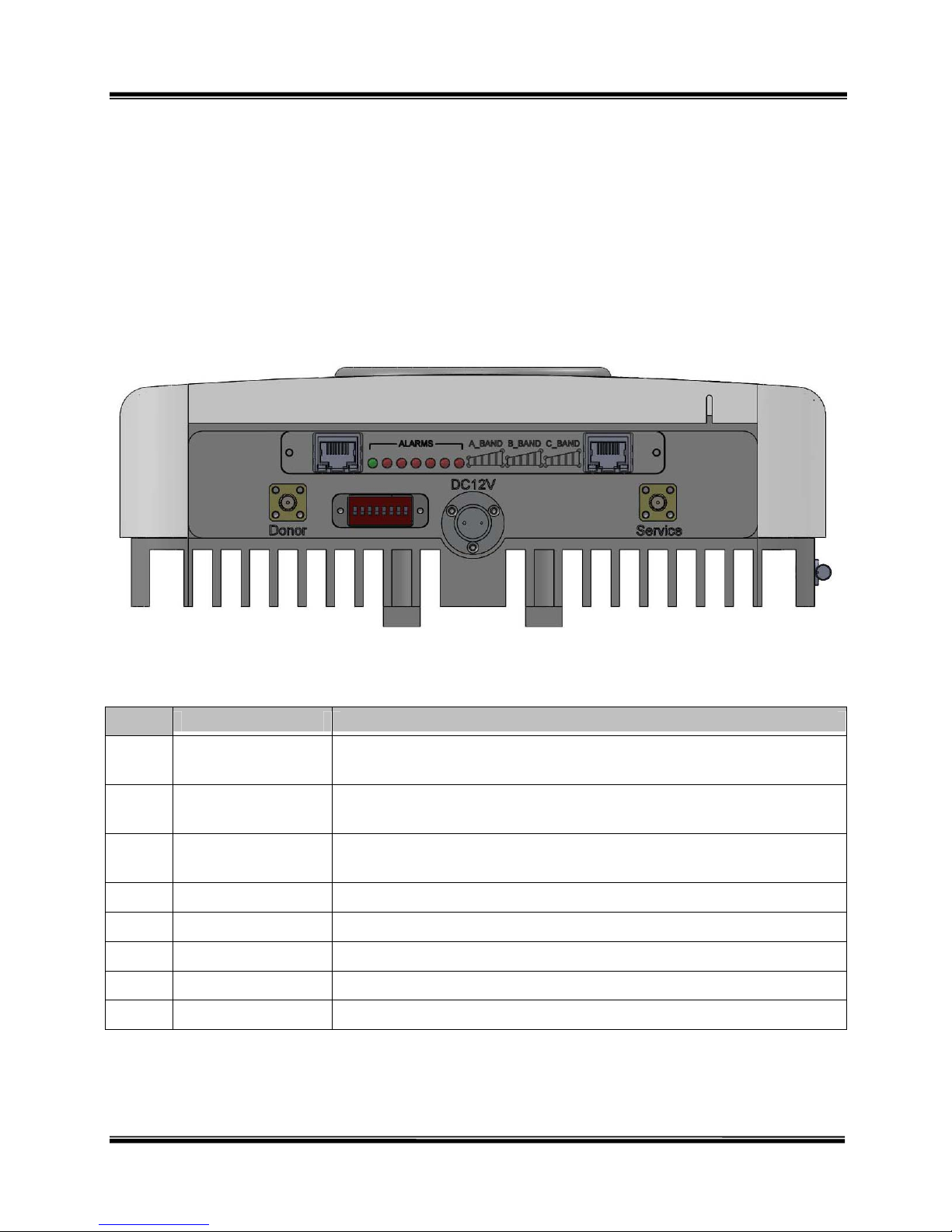
2.4 .........................................................................................................................10 PORT &LED DESCRIPTION
2.5 ........................................................................................................................ 11 FREQUENCY BAND SETTING
2.6 ................................................................................................................................11 ALARM DESCRIPTIONS
3. ...............................................................................................................................................13 INSTALLATION
3.1 ....................................................................................................................13 TRANSPORTATION TO THE SITE
3.2 ......................................................................................................................13 HANDLING OF THE REPEATER
3.3 .........................................................................................................................13 INSTALLATION CONDITIONS
3.4 .........................................................................................14 INSPECTION BEFORE INSTALLING THE REPEATER
3.5 .........................................................................................................................14 INSTALLATION PROCEDURE
3.5.1 .................................................................................................................14 Repeater Cabinet Installation
3.5.2 ..................................................................................................................18 Repeater Cable Connections
3.5.3 ............................................................................................................................19 Powering Up the JL20
3.6 ...............................................................................................................19 CAUTIONS DURING INSTALLATION
3.7 ........................................................................................................................20 STORAGE OF THE REPEATER
3.8 ............................................................................................................................................20 MAINTENANCE
3.9 ................................................................................................................................20 SAFETY INSTRUCTIONS
APPENDIX 1. SYSTEM SPECIFICATIONS .........................................................................................................21
.........................................................................................................................................21 RF SPECIFICATIONS
........................................................................................22 MECHANICAL &ENVIRONMENTAL SPECIFICATIONS
APPENDIX 2. JL20 COMMISSIONING & SETUPCHECKLIST......................................................................23
APPENDIX 3. RISKASSESSMENTAND CONTROLFORM............................................................................28
Repeater Operations Manual Version 2.00
Model: JL20 ©2011 Juni | America Inc.

Important Safety Precautions
The JL20 unit is powered by 12VDC. Only personnel who have received
relevant training from Juni are authorised to open any part or section of the
JL20. To prevent electrical shock when installing or maintaining the equipment,
ensure the supply of VDC (and/or VAC) is removed by switching off the
power from the power source before accessing any section of the equipment.
Only when the Repeater is fully installed and all cable connections are made
should the power be turned on. Ensure all installation items are complete
before turning on the Repeater.
on.
Ensure the total input power to the Repeater is within the range -75dBm ~ -
30dBm. Input powers outside this range may affect Repeater performance.
Ensure frequencies are configured correctly. Incorrect frequency settings can
severely affect Repeater performance.
When installing the Repeater, ensure the heat-sink section of the Repeater is
not exposed to direct sunlight. Where possible, have the heat-sink section of
the Repeater facing a northerly directi
Always observe the warning labels and markings present on the equipment. If
unsure, contact Juni America on +1 800 216 0466 for advice.
The JL20 can weigh up to 5kg. Ensure the correct procedures are used in
moving or lifting the equipment to avoid injury.
Repeater Operations Manual Version 2.00
Model: JL20 ©2011 Juni | America Inc.

1 | INTRODUCTION
1. Introduction
Juni offers a full turn-key solution for LTE Indoor RF repeater. This includes customer service
which is supported by Juni call center (+1 800 216 0466) and installation service. It is designed
to support SOHO and large office coverage area.
It offers quick install by providing everything needed for installation including system, donor and
coverage antennas, required cables, and installation hardware.
Designed for “Plug and Play” installation, the JL20 provides improvements to call quality and
data speed by eliminating problems such as weak and unstable receive and transmit signals in
areas where base station signals cannot penetrate – such as indoor areas, underground parking
stations and subway tunnels.
The JL20 will receive RF signals from a LTE Base Station, amplify this signal then transmit this
amplified signal to the desired coverage area. The maximum output power of the JL20 is rated at
20dBm for both the downlink and uplink paths.
The JL20 also includes a combination of AGC, ALC, and Shutdown/Recovery control circuitry
that ensure superior performance, providing consistent service in areas requiring enhanced
coverage.
The JL20 is also compatible with the Juni Web GUI software platform to allow remote access to
the LMT (Local Maintenance Terminal), providing simple, yet comprehensive monitoring and
control of the Repeater.
With the Juni Web GUI solution, the user can monitor and control the Repeater site using only a
web browser anywhere there is an internet connection. Using SNMP communication, the NOC is
also notified of specific alarms.
Repeater Operations Manual Version 2.00
Model: JL20 ©2011 Juni | America Inc.

2 | SYSTEM DESCRIPTION
Repeater Operation Manual Version 2.00
Model: JL20 ©2008 Juni | America Inc.
2. System Description
2.1 Configuration
The basic configuration of the JL20 is to receive and amplify the base station signal, then re-
transmit this amplified signal to provide coverage for the desired area as shown in the figure
below.
[Figure 1] JL20 Repeater Configuration
As can be seen from figure 1, the JL20 includes two antennas, the Donor and Service antennas.
The Donor Antenna receives and transmits signals from/to the Base Station while the Service
Antenna transmits and receives signals to and from the Mobile Station. The Mobile Station may
include handsets, mobile phones, wireless modems and other CPE (Customer Premises
Equipment).
In addition to the basic Repeater configuration shown above, the JL20 may be used for other
applications such as In-building coverage, tunnel coverage and any other applications that
require coverage enhancements for a small area.
JL20

2 | SYSTEM DESCRIPTION
2.2 Applications
The JL20 is capable of providing solutions for Indoor and SOHO applications. This section
outlines the most typical application scenario suitable for the JL20 Repeater system.
2.2.1 In-Building Coverage Application
JL20
UNITS
BASE
STATION
[Figure 2] In-Building Coverage Application
Because the service antennas are located inside the building, it is often necessary to allow
for aesthetic installations. Small cone type omni antennas are included in the package for
use in setting up coverage.
[Figure 3] Cone Type Antennas for Indoor Use
Repeater Operation Manual Version 2.00
Model: JL20 Page 7 of 28 ©2008 Juni | America Inc.

2 | SYSTEM DESCRIPTION
Repeater Operation Manual Version 2.00
Model: JL20 ©2008 Juni | America Inc.
2.3 General Appearance of the JL20 Repeater
The JL20 Repeater is housed inside a one-body cabinet designed to maximize strength and
heat dissipation. The cabinet is rated at IP43 and is suitable for indoor use.
The design of the cabinet allows for wall mounting of the Repeater via the use of mounting
brackets (supplied). Please see section 3 “Installation” for detailed instructions on the
installation of the JL20 Repeater.
2.3.1 General Appearance
[Figure 4] General Appearance of the JL20 Repeater

2 | SYSTEM DESCRIPTION
2.3.2 Mechanical Drawing
All measurements are shown in inches.
[Figure 5] JL20 Layout – Mechanical Drawing
Repeater Operation Manual Version 2.00
Model: JL20 Page 9 of 28 ©2008 Juni | America Inc.

2 | SYSTEM DESCRIPTION
Repeater Operation Manual Version 2.00
Model: JL20 ©2008 Juni | America Inc.
2.4 Port & LED Description
The JL20 Repeater has 5 (five) connection ports, 2 (two) LEDs, and 1 (one) DIP switch
located on the bottom of the cabinet.
These ports allow for RF, power and monitoring connections as well as Frequency band
settings.
[Figure 6] Connection Ports of the JL20 Repeater
No. Name Description
1 DC12V Connects to the 100~120VAC or 200~240VAC power source.
Port type: 2-pin Military Standard port.
2 Donor Connects to the Donor Antenna.
Port type: SMA-type female
3 Service Connects to the Service Antenna.
Port type: SMA-type female
4 Remote Ethernet RJ45 connection to the modem for Web GUI.
5 Local Ethernet RJ45 connection for local GUI
6 Alarms Alarm indicator LEDs. Refer to Section 2.6
7 RSSI LEDs Signal strength indicator LEDs for each frequency band
8 DIP Switch Used to configure frequency bands. Refer to Section 2.5
[Table 1] Port Descriptions
①
②③
④⑤
⑥
⑦
⑧

2 | SYSTEM DESCRIPTION
Repeater Operation Manual
Model: JL20 Page 11 of 28 ©2008 Juni | America Inc.
2.5 Frequency Band Setting
The DIP Switch described in the previous section comprises of 8 switches. Switches 1 ~ 3
determine the frequency bands, switch 4 enables/disables the AGC function, switch 5
enables/disables the UL Gain Offset function and switches 6~8 are not used.
The following table outlines the DIP switch configurations required for the different frequency
bands. In the illustrations, the position of the actual switch is displayed by the colour “white”.
BW Downlink Uplink DIP SWITCH
A Band 728 ~ 734 698 ~ 704
B Band 734 ~ 740 704 ~ 710
C Band 746 ~ 756 777 ~ 787
[Table 2] DIP Switch Settings
2.6 Alarm Descriptions
The JL20 has a set of LED’s to indicate the current status of the Repeater. If there is an
alarm condition, this can be seen by the ALARM LEDs as described below.
Version 2.00

2 | SYSTEM DESCRIPTION
[Figure 7] ALARMS LED
Name Description
AGC active Lights green when the AGC function is active
Tamper Detect Lights red when the case/cabinet is opened under normal operation
Module Failure Lights red when a PSU or Synthesizer alarm occurs
Reset Engaged Lights red when the MCU is reset
Oscillation Lights red when the oscillation alarm occurs
Shutdown Lights red when the Auto Shutdown function is enabled and engaged.
Donor Low Power Lights red when the DL input signal level is below -75dBm.
[Table 3] ALARM LED Descriptions
Repeater Operations Manual Version 2.00
Model: JL20 ©2011 Juni | America Inc.

3 | INSTALLATION
3. Installation
3.1 Transportation to the Site
During transportation of the Repeater to the site, the following points need to be considered.
While transporting the Repeater unit, ensure the Repeater is packaged in its original
packaging supplied by Juni.
Prevent any unnecessary shock applied to the Repeater units while loading/unloading
to/from the vehicle.
During transportation, it is advised to prevent or minimize any movement of the packed
Repeater units.
3.2 Handling of the Repeater
As the JL20 Repeater is heavy, the installer should be careful and seek assistance while
attempting to lift/carry/move the unit.
To avoid the risk accidental fire or electric shock, do not expose the Repeater to rain or
any other wet condition during installation.
3.3 Installation Conditions
Avoid direct sunlight and place the Repeater in a well ventilated location.
The environment temperature should be in the range of 32F ~ 113F (0C +45C).
Ground connections must be made to all metal cabinets for safety.
Avoid any vibration.
The VSWR of the cable which connects the Repeater to the antenna should be less than
1:1.4.
The cable loss between the Repeater ports and the antenna should be less than 3dB for
optimal performance.
Although the Repeater cabinet is rated as IP43, it is advised to use waterproofing tape
around the connection area of the antenna and power ports.
Repeater Operation Manual Version 2.00
Model: JL20 Page 13 of 28 ©2008 Juni | America Inc.

3 | INSTALLATION
Repeater Operation Manual Version 2.00
Model: JL20 ©2008 Juni | America Inc.
3.4 Inspection before Installing the Repeater
Check if there is any physical damage on the Repeater cabinet. If any damage is found, it
is advised to perform close inspection on the operating features and RF signal test to
verify Repeater performance.
Check if there are any loose RF cables inside and/or outside the Repeater.
Check if there’s any part of the cabinet exposed to water or other liquid substances.
Before installing the Repeater, check the serial number of the units to be installed.
Confirm the correct accessories have been supplied.
3.5 Installation Procedure
3.5.1 Repeater Cabinet Installation
The JL20 can be mounted on a wall or the ceiling. This section describes how the Repeater
can be mounted on three different surfaces – lumber, drywall (gypsum, plasterboard) and
concrete.
On all surfaces, the mounting is achieved by combining the two mounting brackets – one for
the Repeater (Bracket A) and one for the surface (Bracket B).
[Figure 8] Mounting Brackets A (shown on left) & B (shown on right)

3 | INSTALLATION
To install Bracket A to the back of the Repeater, see the figure below.
[Figure 9] Installing Bracket A
3.5.1.1 Lumber Mounting
1) Using the timber screws specified in the figure below, firmly attach the Bracket B to the
desired location.
[Figure 10] Mounting Bracket – Lumber Mounting
Repeater Operation Manual Version 2.00
Model: JL20 Page 15 of 28 ©2008 Juni | America Inc.

3 | INSTALLATION
Repeater Operation Manual Version 2.00
Model: JL20 ©2008 Juni | America Inc.
3.5.1.2 Drywall (Gypsum/Plasterboard) Mounting
1) Using the Bracket B as a template, mark the location of the four holes to be screwed.
2) Screw the drywall anchors to the four marked holes as shown below.
3) Firmly attach the Bracket B to the drywall using the anchor screws as shown below.
[Figure 11] Mounting Bracket – Drywall Mounting
3.5.1.3 Concrete Mounting
1) Using the Bracket B as a template, mark the location of the four holes to be drilled.
2) Drill four 6mm holes 30~40mm deep. Insert plastic anchors into the holes.
3) Firmly attach the Bracket B to the surface by using the screws as shown below.
[Figure 12] Mounting Bracket – Concrete Mounting

3 | INSTALLATION
3.5.1.4 Mounting Complete
Once Brackets A and B have been both installed, complete the mounting process by
combing the two brackets as shown below.
[Figure 13] Mounting Complete
Repeater Operation Manual Version 2.00
Model: JL20 Page 17 of 28 ©2008 Juni | America Inc.

3 | INSTALLATION
Repeater Operation Manual Version 2.00
Model: JL20 ©2008 Juni | America Inc.
3.5.2 Repeater Cable Connections
[Figure 14] Cable Connections
1) Confirm the Repeater unit has been mounted firmly and securely onto the mounting
bracket.
2) Confirm that the Repeater is connected to the common ground using the Earth Terminal
located on the bottom of the Repeater.
3) Connect the Donor antenna cable to the “Donor” port of the Repeater. The “Donor” port
is an SMA-type female connection.
4) Connect the Service antenna cable to the “Service” port of the Repeater. The “Service”
port is an SMA-type female connection.
5) Connect the DC Power adapter to the “DC12V” port of the Repeater. The AC power
source should be 110VAC or 220VAC.
6) Connect an Ethernet cable from the “Remote Ethernet” port to the modem.
7) Confirm all connections are correct and firm.
To power source
To Donor Antenna To Service Antenna
To Modem

3 | INSTALLATION
3.5.3 Powering Up the JL20
CAUTION
Before supplying power to the unit, ensure the AC power source is correct and
stable. Confirm there is sufficient earth connection to the cabinet by connecting
an earth cable to the Earth Terminal on the bottom of the Repeater unit.
1) Confirm the AC voltage of the source is 110VAC or 220VAC.
2) Confirm the Power adapter is working correctly and supplying 12VDC.
3) Confirm all connections are firm and correct.
4) Turn the Repeater ON by switching on the power source.
3.6 Cautions during Installation
1) Ensure AC power is isolated before commencing ANY work.
●Only personnel who have received relevant training from Juni are authorized to
open any part or section of the JL20.
●To prevent electrical shock when installing or maintaining the equipment, ENSURE
THE SUPPLY OF AC IS REMOVED by switching off the AC from the source before
accessing ANY section of the equipment.
2) Ensure the earth connections are made.
●Attach all grounding cables to the Earth Terminals using the appropriated Crimp Tool.
●Confirm the ground connection complies with the specifications for protection
against electrical shocks.
3) Supply power to the equipment only after the correct cable connections are made.
●All cable connections should be made correctly before supplying AC power to the
equipment.
4) Ensure AC mains power cable is weather protected.
●The AC mains power cable should be enclosed in UV resistant conduit.
●Care should be taken to ensure no part of the power cable is exposed.
Repeater Operation Manual Version 2.00
Model: JL20 Page 19 of 28 ©2008 Juni | America Inc.

3 | INSTALLATION
Repeater Operation Manual
Model: JL20 ©2008 Juni | America Inc.
Version 2.00
3.7 Storage of the Repeater
When storing the Repeater, it is recommended to pack the Repeater in its original
packaging supplied by Juni.
The Repeater should not be stored in a high temperature or humid environment. Avoid
direct sunlight.
3.8 Maintenance
The Repeater should not require regular maintenance under normal operation, however,
it is recommended to check the condition of the Repeater occasionally for any abnormal
alarms.
The Repeater can be remotely monitored and controlled using the Juni Web GUI system.
If the Repeater requires cleaning, avoid static electricity and use a dry cloth.
3.9 Safety Instructions
To avoid the risk of accidental electric shock, do not touch the contact terminals on the
power supply unit or the control board during normal operation. If replacement is required,
the power of the Repeater should be turned ‘OFF’ before taking any action.
To avoid the risk of accidental fire or electric shock, do not expose this product to rain or
any other wet condition during installation or maintenance.
Only a qualified technician should service this Repeater. Opening or removing covers
may expose you to dangerous voltage and/or other risks. Incorrect assembly may cause
electric shock when the appliance is subsequently used.
Observe ALL warning and caution labels on the equipment and in this document.
Table of contents