Important Safety Precautions
INSTRUCTIONS
1. DISASSEMBLY
1.1 BEFORE ASSEMBLY AND DISASSEMBLY ......................... 1-1
1.1.1 Precautions ..................................................................... 1-1
1.1.2 Assembly and disassembly ............................................ 1-1
1.1.3 Destination of connectors ............................................... 1-1
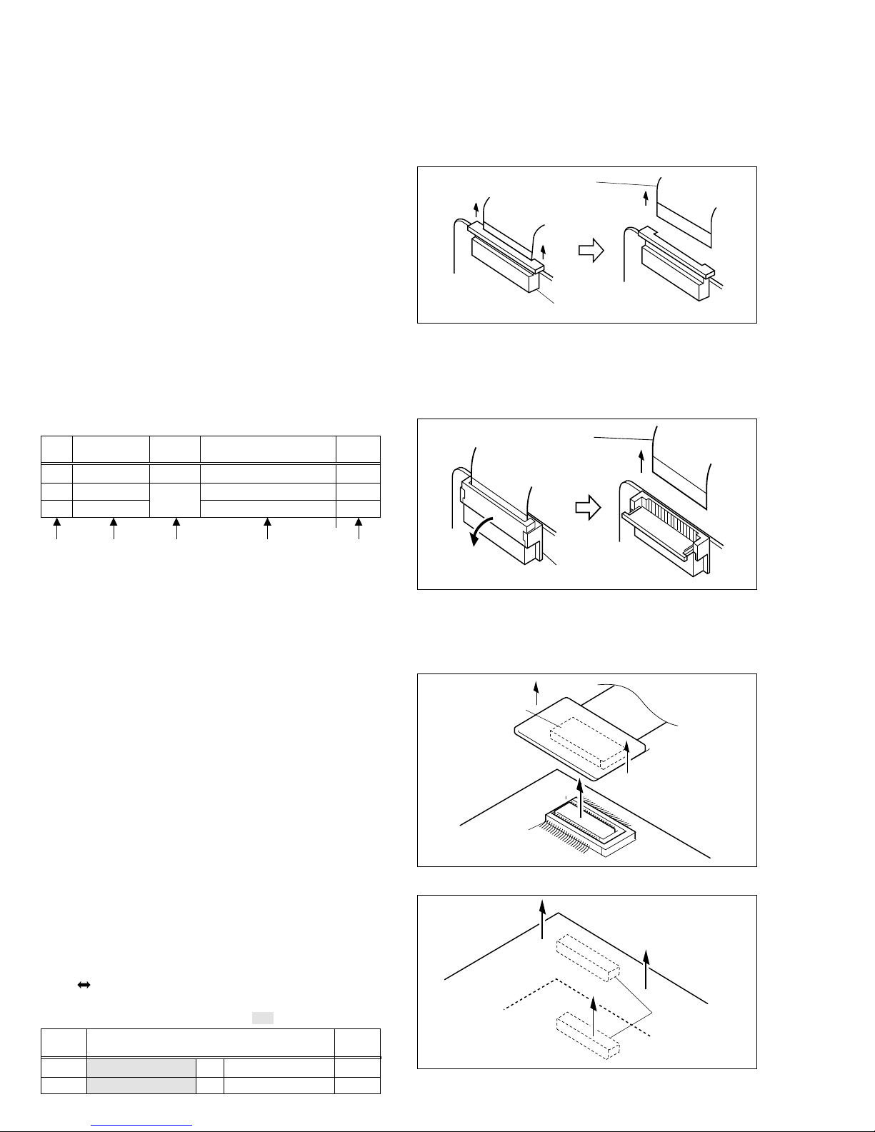
1.1.4 Disconnection of Connectors (Wires) ............................. 1-1
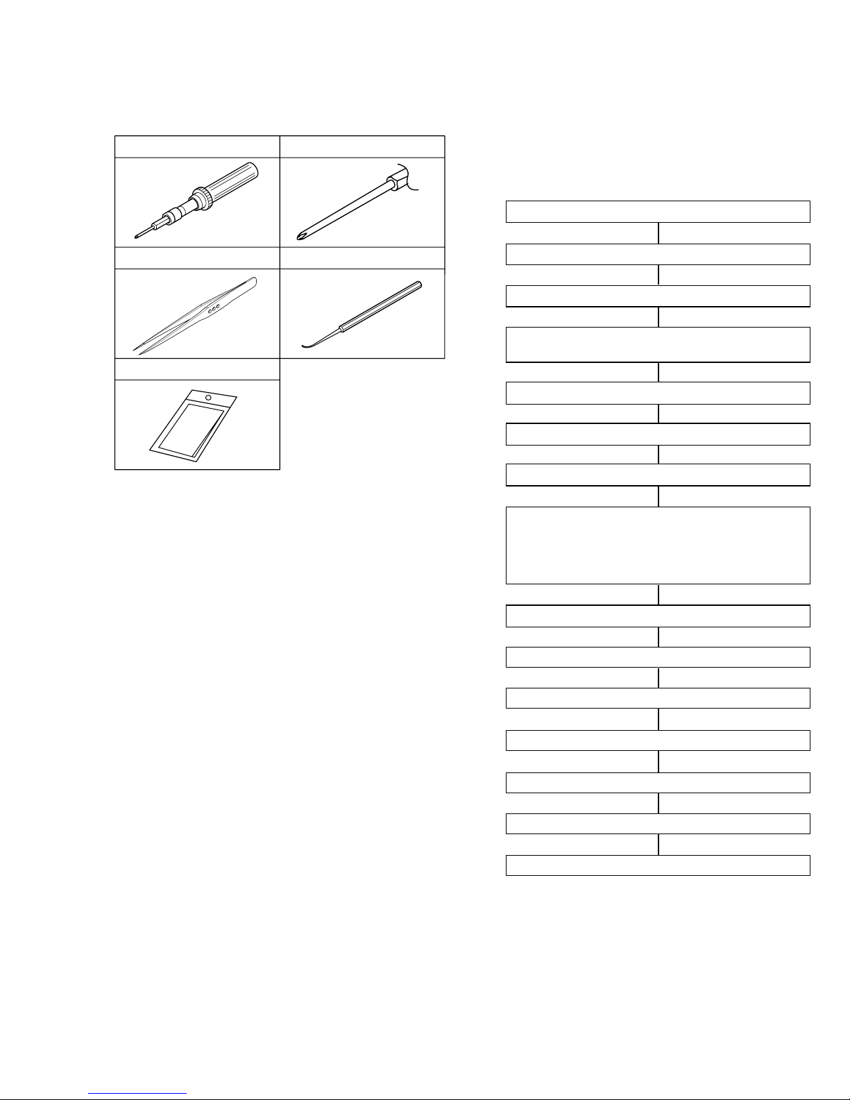
1.2 JIGS AND TOOLS REQUIRED FOR DISASSEMBLY,
ASSEMBLY AND ADJUSTMENT ......................................... 1-2
1.2.1 Tools required for adjustments ........................................ 1-2
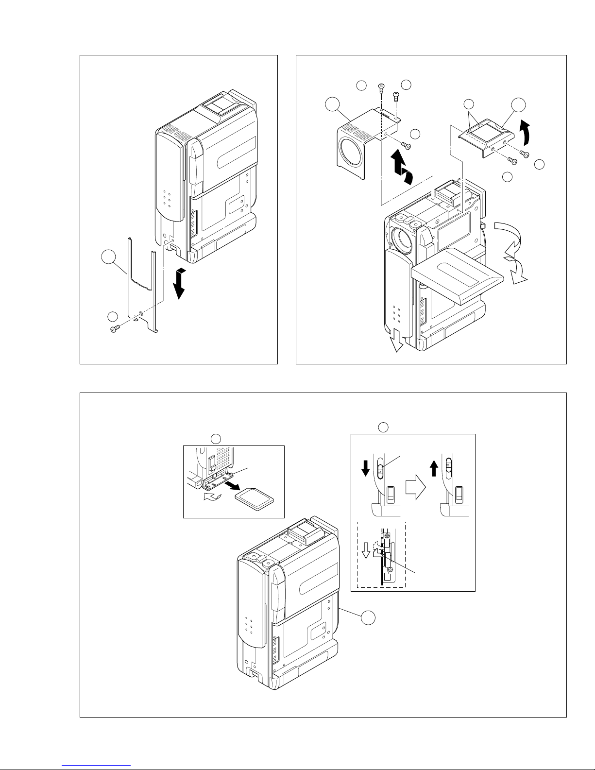
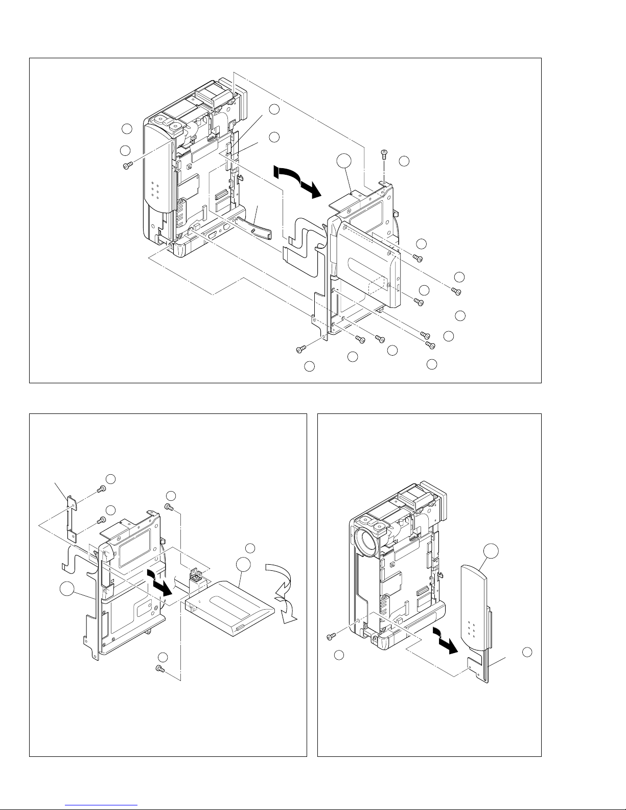
1.3 DISASSEMBLY/ASSEMBLY OF CABINET PARTS AND
BOARD ASSEMBLY ............................................................. 1-2
1.3.1 Disassembly flow chart ................................................... 1-2
1.3.2 Disassembly method ...................................................... 1-3
1.4 DISASSEMBLY OF 5MONITOR ASSEMBLY ..................... 1-8
1.4.1 5Monitor assembly/Hinge assembly ............................. 1-8
1.4.2 Hinge assembly .............................................................. 1-8
1.5 DISASSEMBLY OF @OP BLOCK ASSEMBLY/CCD
BOARD ASSEMBLY ............................................................. 1-9
1.5.1 Precautions ..................................................................... 1-9
1.5.2 How to remove @OP block assembly and CCD board
assembly ......................................................................... 1-9
1.5.3 How to install @OP block assembly and CCD board
assembly ......................................................................... 1-9
1.5.4 Replacement of service parts ......................................... 1-9
1.6 DISASSEMBLY OF #E. VF ASSEMBLY ............................ 1-10
1.6.1 #E. VF assembly ......................................................... 1-10
1.7 EMERGENCY DISPLAY ..................................................... 1-11
1.8 SERVICE KNOW-HOW ....................................................... 1-12
1.9 SERVICE NOTE .................................................................. 1-14
2. MECHANISM ADJUSTMENT
2.1
PRELIMINARY REMARKS ON ADJUSTMENT AND REPAIR ..
2-1
2.1.1 Precautions ..................................................................... 2-1
2.1.2 Notes on procedure for disassemby/assembly ............... 2-1
2.2 JIGS AND TOOLS REQUIRED FOR DISASSEMBLY,
ASSEMBLY AND ADJUSTMENT ......................................... 2-2
2.2.1 Tools required for adjustments ........................................ 2-2
2.3 DISASSEMBLY/ASSEMBLY OF MECHANISM ASSEMBLY 2-3
2.3.1 General statement .......................................................... 2-3
2.3.2 Explanation of mechanism mode ................................... 2-3
2.3.3 Mechanism timing chart .................................................. 2-4
2.4 DISASSEMBLING PROCEDURE TABLE ............................. 2-5
2.4.1 Disassembly/assembly ................................................... 2-7
2.4.2 List of procedures for disassembly ............................... 2-13
2.5
CHECKUP AND ADJUSTMENT OF MECHANISM PHASE .
2-14
2.6 MECHANISM ADJUSTMENTS .......................................... 2-15
2.6.1 Adjustment of the slide guide plate ............................... 2-15
2.6.2
Adjustment of the Tension Arm and Pad Arm Assemblies ..
2-16
2.6.3 Adjustment of the Slide Lever 2 .................................... 2-16
2.7 SERVICE NOTE .................................................................. 2-17
2.8 COMPATIBILITY ADJUSTMENT ........................................ 2-19
2.8.1 Jig connector cable connection .................................... 2-19
2.8.2 Tape pattern check ....................................................... 2-19
TABLE OF CONTENTS
Section Title Page Section Title Page
3. ELECTRICAL ADJUSTMENT
3.1 PRECAUTION ....................................................................... 3-1
3.2 SETUP .................................................................................. 3-2
4. CHARTS AND DIAGRAMS
NOTES OF SCHEMATIC DIAGRAM .......................................... 4-1
CIRCUIT BOARD NOTES ........................................................... 4-2
4.1 BOARD INTERCONNECTIONS ........................................... 4-3
4.2
SYSCON-CPU SCHEMATIC DIAGRAM .................................... 4-5
4.3 SERVO SCHEMATIC DIAGRAM ................................................ 4-7
4.4 MDA SCHEMATIC DIAGRAM .................................................... 4-9
4.5 AUDIO AD/DA SCHEMATIC DIAGRAM ................................... 4-11
4.6 MAIN AUDIO SCHEMATIC DIAGRAM ..................................... 4-13
4.7 DV MAIN SCHEMATIC DIAGRAM ........................................... 4-15
4.8 PRE/REC SCHEMATIC DIAGRAM .......................................... 4-17
4.9 VIDEO I/O SCHEMATIC DIAGRAM ......................................... 4-19
4.10 CDS/AD SCHEMATIC DIAGRAM .......................................... 4-21
4.11 CAM.DSP SCHEMATIC DIAGRAM ....................................... 4-23
4.12 TG/VDR SCHEMATIC DIAGRAM .......................................... 4-25
4.13 REGCON SCHEMATIC DIAGRAM ........................................ 4-27
4.14 REG SCHEMATIC DIAGRAM ................................................ 4-29
4.15 VF MAIN SCHEMATIC DIAGRAM ......................................... 4-31
4.16 MONITOR MAIN SCHEMATIC DIAGRAM ............................. 4-33
4.17 DSC SCHEMATIC DIAGRAM ................................................ 4-35
4.18 USBDRV SCHEMATIC DIAGRAM ......................................... 4-37
4.19 SD SCHEMATIC DIAGRAM ................................................... 4-39
4.20 WBSEN/SW SCHEMATIC DIAGRAM .................................... 4-41
4.21 OPDRV SCHEMATIC DIAGRAM ........................................... 4-43
4.22 BOTTOM SCHEMATIC DIAGRAM ........................................ 4-45
4.23 MONITOR SCHEMATIC DIAGRAM ....................................... 4-47
4.24 W/B AND CCD SCHEMATIC DIAGRAMS ............................. 4-49
4.25 EJECT AND VF BL SCHEMATIC DIAGRAMS ...................... 4-50
4.26 MAIN CIRCUIT BOARD ......................................................... 4-51
4.27 OP MDA CIRCUIT BOARD .................................................... 4-57
4.28 BOTTOM CIRCUIT BOARD ................................................... 4-59
4.29 MONITOR, CCD, EJECT AND VF BL CIRCUIT BOARDS .... 4-61
4.30 VOLTAGE CHARTS ............................................................... 4-63
4.31 POWER SYSTEM BLOCK DIAGRAM ................................... 4-67
4.32 VIDEO SYSTEM BLOCK DIAGRAM ...................................... 4-69
5. PARTS LIST
5.1 PACKING AND ACCESSORY ASSEMBLY <M1> ............... 5-1
5.2 FINAL ASSEMBLY <M2> ..................................................... 5-3
5.3 MECHANISM ASSEMBLY <M3> ......................................... 5-6
5.4 ELECTRONIC VIEWFINDER ASSEMBLY <M4> ................ 5-8
5.5 MONITOR ASSEMBLY <M5> .............................................. 5-9
5.6 ELECTRICAL PARTS LIST ................................................. 5-10
MAIN BOARD ASSEMBLY <01> ............................................. 5-10
OP MDA BOARD ASSEMBLY <02> ........................................ 5-19
BOTTOM BOARD ASSEMBLY <03> ....................................... 5-20
MONITOR BOARD ASSEMBLY <04> ..................................... 5-20
CCD BOARD ASSEMBLY <05> .............................................. 5-21
EJECT BOARD ASSEMBLY <06> .......................................... 5-21
VF BL BOARD ASSEMBLY <07> ............................................ 5-21