JVC GR-FX15EK User manual

No. 86718
2003/02
COMPACT VHS CAMCORDER
Regarding service information other than these sections, refer to the service manual No. 86712 (GR-SX25EX).
Also, be sure to note important safety precautions provided in the service manual.
GR-FX15EK,GR-FX15EX,GR-FX15EY,GR-FX15EZ
SERVICE MANUAL
SPECIFICATION
Camcorder
General
Connectors
AC Adapter
Format :S-VHS(GR-SXM49/SX25 only)/
VHS PAL standard
Power source :DC 11 V (Using AC Adapter)
DC 6 V (Using battery pack)
Power consumption
Viewfinder on :4.2 W (GR-SXM49/FXM393/FXM39 only)
4.0 W (GR-SX25/FX15 only)
LCD monitor* on :4.7 W (GR-SXM49/FXM393/FXM39 only)
Video light** :3.0W
* Applicable models only.
** GR-SXM49/FXM393/SX25 only.
Signal system :PAL-type
Video recording system
Luminance :FMrecording
Colour :Converted sub-carrier direct recording
Conforms to VHS standard
Cassette : /cassette
Tape speed
SP :23.39 mm/sec.
LP :11.70 mm/sec.
Recording time (max.)
SP :60minutes
LP :120minutes (with EC-60 cassette)
Operating
temperature :0°Cto 40°C
Operating humidity :35% to 80%
Storage temperature :-20°Cto 50°C
Weight :Approx. 840 g (GR-SXM49/FXM393/FXM39 only)
Approx. 760 g (GR-SX25 only)
Approx. 750 g (GR-FX15 only)
Dimensions (W x H x D) :113mm x 117 mm x 199 mm
(GR-SXM49/FXM393/FXM39 only)
108 mm x 117 mm x 199 mm (GR-SX25/FX15 only)
(with the LCD monitor* closed and with the
viewfinder fully tilted downward)
* Applicable models only.
Pickup :1/6"format CCD
Lens :F1.6, f = 2.7 mm to 43.2 mm,
16:1 power zoom lens with auto iris and
macro control, filter diameter 40.5 mm
Viewfinder :Electronic viewfinder with 0.5"
black/white CRT White balance
White balance
adjustment
:Auto/Manual adjustment
Speaker
(Applicable models only)
:Monaural
LCD monitor
(Applicable models only)
:2.5"diagonally measured, LCD panel/
TFT active matrix system
Video
:
1 V (p-p), 75 unbalanced, analogue output
(via Video output connector)
Audio
:
300 mV (rms), 1 k , analogue output
(via Audio output connector)
S-Video
(GR-SXM49/SX25 only)
:
Y:1V(p-p), 75 , analogue output
C:0.30V(p-p),75 , analogue output
Power requirement
:
AC 110 V - 240 V ~, 50 Hz/60 Hz
Output
:
DC 11 V , 1 A
Optional Accessories
• Battery Packs BN-V12U, BN-V20U, BN-V400U
• Compact S-VHS ( ) Cassettes SE-C45/30
• Compact VHS ( ) Cassettes EC-60/45/30
• Active Carrying Bag CB-V7U
• Cassette Adapter C-P7U
Some accessories are not available in some areas. Please consult your
nearest JVC dealer for details on accessories and their availability.
(The specifications shown pertain specifically to the model GR-SXM49, FXM393, FXM39, SX25, FX15)
GR-FX15EK,GR-FX15EX,GR-FX15EY,GR-FX15EZ M3A6B2

TABLE OF CONTENTS
DIFFERENT TABLE .................................................................................................................................................................................... 1 to 2
PARTS LIST
1. PACKING AND ACCESSORY ASSEMBLY <M1> ..................................................................................................................................... 3-1
1
The following table indicate main different points between models GR-SX25EX ,GR-FX15EK ,GR-FX15EX ,GR-FX15EY and
GR-FX15EZ.
The following table indicate different parts number between models GR-SX25EX ,GR-FX15EK ,GR-FX15EX ,GR-FX15EY
and GR-FX15EZ.
!REF. MODEL GR-SX25EX GR-FX15EK GR-FX15EX GR-FX15EY GR-FX15EZ
NO. ITEM
PACKING AND ACCESSORY ASSEMBLY <M1>
MODEL GR-SX25EX GR-FX15EK GR-FX15EX GR-FX15EY GR-FX15EZ
ITEM
TAPE FORMAT S-VHS-C VHS-C
S CABLE Used Not used
S OUTPUT Used Not used
DC LIGHT Used Not used
1 PACKING CASE LY33071-002B LY33071-004B
4 POLY BAG QPA02003506 QPA02003506P QPA02003506
!5 INST BOOK(GERMAN) LYT1060-002C — LYT1060-002C —
!5 INST BOOK(FRENCH) LYT1060-003C — LYT1060-003C — —
!5 INST BOOK(DUTCH) LYT1060-004C — LYT1060-004C — —
!5 INST BOOK(SPANISH) LYT1060-005C — LYT1060-005C — —
!5 INST BOOK(ITALIAN) LYT1060-006C — LYT1060-006C — —
!5 INST BOOK(ENGLISH) — LYT1061-001B — — —
!5 INST BOOK(DANISH) — — — LYT1060-007B —
!5 INST BOOK(FINNISH) — — — LYT1060-008B —
!5 INST BOOK(SWEDISH) — — — LYT1060-009B —
!5 INST BOOK(NORWEGIAN) — — — LYT1060-010B —
!5 INST BOOK(RUSSIAN) — — — — LYT1060-011B
!5 INST BOOK(CZECH) — — — — LYT1060-012B
!5 INST BOOK(POLISH) — — — — LYT1060-013B
!5 INST BOOK(HUNGARIAN) — — — — LYT1060-014B
6 Q.CARD — LYT1094-001B — — —
7 GUARANTY CARD — BT-54008-4 — — —
8 WARRANTY CARD BT-54013-5 — BT-54013-5
9 POLY BAG QPA02003506 QPA02003506P QPA02003506
!14 AC ADAPTER LY20955-001C ———
!14 AC ADAPTER LY20956-001B
16 S CABLE QAM0004-003 — — — —
!17 POWER CORD QMPL120-190-JR QMPP110-190-JR QMPL120-190-JR
Notes : Mark is same as left.
Mark — is not used.

2
!REF. MODEL GR-SX25EX GR-FX15EK GR-FX15EX GR-FX15EY GR-FX15EZ
NO. ITEM
MECHANISM ASSEMBLY <M3>
400 MECHA(B) ASSY YMA0040A-E YMA0042A-E
406
CASSETTE GUIDE ASSY(RIGHT)
YQ44339A-7 — — — —
406A SW.LEVER(RIGHT) YQ32162-1-3 — — — —
406B TORSION SPRING YQ44340-1-4 — — — —
407 SCREW LY42819-001A — — — —
466 ROTARY ENCODER QSW0888-002 QSW0888-001
Notes : Mark is same as left.
Mark — is not used.
!REF. MODEL GR-SX25EX GR-FX15EK GR-FX15EX GR-FX15EY GR-FX15EZ
NO. ITEM
MAIN BOARD ASSEMBLY <01>
PW1 MAIN BOARD ASSY YB10400EB1-02 YB10400EI1-03
IC4002 IC(DIGITAL) MSM548331TA — — — —
IC4701 IC — MM1512XN-X
IC4702 IC BA7665FS-X — — — —
Q3505 DIGI TRANSISTOR DTC144EE-X — — — —
Q4001 DIGI TRANSISTOR DTC144EE-X — — — —
Q6306 MOS FET 2SK3577-X — — — —
D4001 SI DIODE DAN222-X — — — —
C4024 C CAPACITOR NCF31EZ-104X — — — —
C4025 C CAPACITOR NCB31CK-104X — — — —
C4044 C CAPACITOR NCB30JK-105X — — — —
C4713 E CAPACITOR NEA70JM-226X — — — —
C4714 E CAPACITOR NEA70GM-107X — — — —
C4715 C CAPACITOR NCB31EK-103X — — — —
C6307 E CAPACITOR NEA71CM-106X — — — —
R4013 MG RESISTOR NRSA63J-102X — — — —
R4014 MG RESISTOR NRSA63J-103X — — — —
R4036 MG RESISTOR NRSA63J-101X — — — —
R4712 MG RESISTOR NRSA63D-680X — — — —
R4713 MG RESISTOR NRSA63D-680X — — — —
R6306 MG RESISTOR NRSA63J-0R0X — — — —
R6307 MG RESISTOR NRSA63J-104X — — — —
R6314 MG RESISTOR NRS12BK-R47W — — — —
CN6 CONNECTOR QGA1201C2-02X — — — —
J505 S JACK QND0068-001 — — — —
!REF. MODEL GR-SX25EX GR-FX15EK GR-FX15EX GR-FX15EY GR-FX15EZ
NO. ITEM
FINAL ASSEMBLY <M2>
101 C.COVER(S)ASSY LY20928-001D LY20928-007E LY20928-006E
101F STICKER(C) LY44007-001A — LY44007-001A
101H STICKER(B) LY43982-001A LY43982-005A
121 LOWER CASE ASSY LY20925-002C LY20925-006E
135 F.COVER ASSY LY20926-001C LY20926-003D
135D STICKER(A) LY43983-001A LY43983-002A
!135E CAUTION LABEL LY44141-001A — — — —
135G COVER(LIGHT) — LY32965-001A
137 DC LIGHT LY33067-001A — — — —
157 TOP OPE UNIT LY10392-001C LY10392-002D
135
135C
135B
135A
135F
135F
135D
135F
136
g
m
f
139
a
135G
As for the difference in a “FINAL ASSEMBLY <M2>”
drawing, 135G is added.

3-1
PARTS LIST
SAFETY PRECAUTION
Parts identified by the !symbol are critical for safety. Replace only with specified part numbers.
1. PACKING AND ACCESSORY ASSEMBLY <M1>
The instruction manual to be provided with this product will differ according to the destination.
1 LY33071-004B PACKING CASE
2 LY33075-001B CUSHION
3 LY30023-002A POLY BAG
4 QPA02003506P POLY BAG 20cm x 35cm A
4 QPA02003506 POLY BAG 20cm x 35cm B,C,D
!
5 LYT1061-001B INST BOOK (ENGLISH) A
!
5 LYT1060-002C INST BOOK (GERMAN) B,C
!
5 LYT1060-003C INST BOOK (FRENCH) B
!
5 LYT1060-004C INST BOOK (DUTCH) B
!
5 LYT1060-005C INST BOOK (SPANISH) B
!
5 LYT1060-006C INST BOOK (ITALIAN) B
!
5 LYT1060-007B INST BOOK (DANISH) C
!
5 LYT1060-008B INST BOOK (FINNISH) C
!
5 LYT1060-009B INST BOOK (SWEDISH) C
!
5 LYT1060-010B INST BOOK
(NORWEGIAN)
C
!
5 LYT1060-011B INST BOOK (RUSSIAN) D
!
5 LYT1060-012B INST BOOK (CZECH) D
!
5 LYT1060-013B INST BOOK (POLISH) D
!
5 LYT1060-014B INST BOOK (HUNGARIAN) D
6 LYT0194-001B Q.CARD (JUK) A
7 BT-54008-4 GUARANTY CARD A
8 BT-54013-5 WARRANTY CARD B,C,D
9 QPA02003506P POLY BAG 20cm x 35cm A
9 QPA02003506 POLY BAG 20cm x 35cm B,C,D
!
10 YQ10629E BATTERY PACK ASSY
11 PEMC1174 CONNECTOR
13 LY43388-001A LENS CAP ASSY
!
14 LY20956-001B AC ADAPTER AP-V11E
!
14 or LY20955-001C AC ADAPTER AP-V13E A
15 PEAC0362-150 A/V RCA CABLE
!
17 QMPP110-190-JR POWER CORD(EK) 1.9m BLACK A
!
17 QMPL120-190-JR POWER CORD(EU) 1.9m BLACK B,C,D
19 LY20186-001A SHOULDER STRAP
5
1
19
10
17
11
14
LABEL
(SERIAL)
6
8
7
15
MODEL MARK
GR-FX15EK A
GR-FX15EX B
GR-FX15EY C
GR-FX15EZ D
13
2
9
4
FINAL ASSEMBLY
<M2>
3
!Symbol No. Part No. Part Name Description Local
PACKING AND ACCESSORY ASSEMBLY <M1>
(Sanwa)-M3A6B2
GR-FX15EK,GR-FX15EX,GR-FX15EY,GR-FX15EZE. & O. E. No. 86718

SERVICE MANUAL
COPYRIGHT © 2003 VICTOR COMPANY OF JAPAN, LTD. No.86712
2003/01
COMPACT VHS CAMCORDER
86712200301
GR-SX25EK,GR-SX25EX,GR-SX25EZ
GR-SXM49EK,GR-SXM49EX,GR-SXM49EZ
SPECIFICATION
Camcorder
General
Connectors
AC Adapter
VHS
PAL
625
For disassembling and assembling of MECHANISM ASSEMBLY, refer to the SERVICE MANUAL No.86700 (MECHANISM ASSEMBLY).
Format : S-VHS (GR-SXM49/SX25 only)/
VHS PAL standard
Power source : DC 11 V (Using AC Adapter)
DC 6 V (Using battery pack)
Power consumption
Viewfinder on : 4.2 W (GR-SXM49/FXM393/FXM39 only)
4.0 W (GR-SX25/FX15 only)
LCD monitor* on : 4.7 W (GR-SXM49/FXM393/FXM39 only)
Video light** :3.0W
* Applicable models only.
** GR-SXM49/FXM393/SX25 only.
Signal system :PAL-type
Video recording system
Luminance : FM recording
Colour : Converted sub-carrier direct recording
Conforms to VHS standard
Cassette : / cassette
Tape speed
SP : 23.39 mm/sec.
LP : 11.70 mm/sec.
Recording time (max.)
SP : 60 minutes
LP : 120 minutes (with EC-60 cassette)
Operating
temperature : 0ºC to 40ºC
Operating humidity : 35% to 80%
Storage temperature : -20ºC to 50ºC
Weight : Approx. 840 g (GR-SXM49/FXM393/FXM39 only)
Approx. 760 g (GR-SX25 only)
Approx. 750 g (GR-FX15 only)
Dimensions (W x H x D) : 113 mm x 117 mm x 199 mm
(GR-SXM49/FXM393/FXM39 only)
108 mm x 117 mm x 199 mm (GR-SX25/FX15 only)
(with the LCD monitor* closed and with the
viewfinder fully tilted downward)
* Applicable models only.
Pickup : 1/6" format CCD
Lens : F1.6, f = 2.7 mm to 43.2 mm,
16:1 power zoom lens with auto iris and
macro control, filter diameter 40.5 mm
Viewfinder : Electronic viewfinder with 0.5"
black/white CRT White balance
White balance
adjustment
: Auto/Manual adjustment
Speaker
(Applicable models only)
: Monaural
LCD monitor
(Applicable models only)
: 2.5" diagonally measured, LCD panel/
TFT active matrix system
Video :1 V (p-p), 75 unbalanced, analogue output
(via Video output connector)
Audio :300 mV (rms), 1 k , analogue output
(via Audio output connector)
S-Video
(GR-SXM49/SX25 only)
:Y: 1 V (p-p), 75 , analogue output
C: 0.30 V (p-p), 75 , analogue output
Power requirement :AC 110 V - 240 V ~, 50 Hz/60 Hz
Output :DC 11 V , 1 A
Optional Accessories
• Battery Packs BN-V12U, BN-V20U, BN-V400U
• Compact S-VHS ( ) Cassettes SE-C45/30
• Compact VHS ( ) Cassettes EC-60/45/30
• Active Carrying Bag CB-V7U
• Cassette Adapter C-P7U
Some accessories are not available in some areas. Please consult your
nearest JVC dealer for details on accessories and their availability.
GR-SX25EK, GR-SX25EX, GR-SX25EZ, GR-SXM49EK, GR-SXM49EX, GR-SXM49EZ M3C7B3,M3C723

TABLE OF CONTENTS
1 PRECAUTIONS. . . . . . . . . . . . . . . . . . . . . . . . . . . . . . . . . . . . . . . . . . . . . . . . . . . . . . . . . . . . . . . . . . . . . . . . . . . . . . . . . . .1-3
1.1 SAFTY PRECAUTIONS . . . . . . . . . . . . . . . . . . . . . . . . . . . . . . . . . . . . . . . . . . . . . . . . . . . . . . . . . . . . . . . . . . . . . .1-3
2 SPECIFIC SERVICE INSTRUCTIONS . . . . . . . . . . . . . . . . . . . . . . . . . . . . . . . . . . . . . . . . . . . . . . . . . . . . . . . . . . . . . . . . .1-5
2.1 BEFORE ASSEMBLY AND DISASSEMBLY . . . . . . . . . . . . . . . . . . . . . . . . . . . . . . . . . . . . . . . . . . . . . . . . . . . . . .1-5
2.2 ASSEMBLY AND DISASSEMBLY OF CABINET PARTS . . . . . . . . . . . . . . . . . . . . . . . . . . . . . . . . . . . . . . . . . . . .1-6
2.3 ASSEMBLY AND DISASSEMBLY OF CAMERA SECTION AND BOARD ASSEMBLY . . . . . . . . . . . . . . . . . . . .1-10
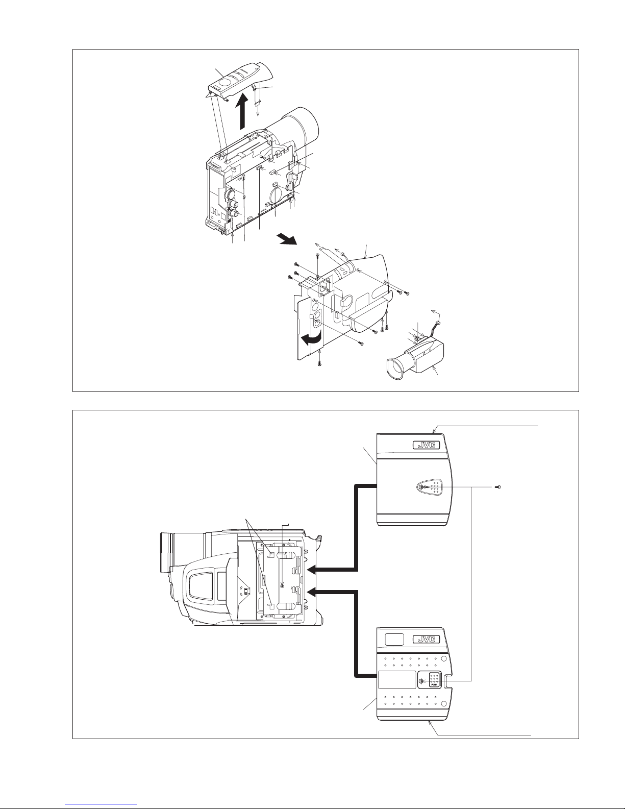
2.4 ASSEMBLY AND DISASSEMBLY OF [7]MONITOR ASSEMBLY (CABINET PARTS) . . . . . . . . . . . . . . . . . . . . .1-12
2.5 ASSEMBLY AND DISASSEMBLY OF [2]OP BLOCK ASSEMBLYCCD BOARD ASSEMBLY
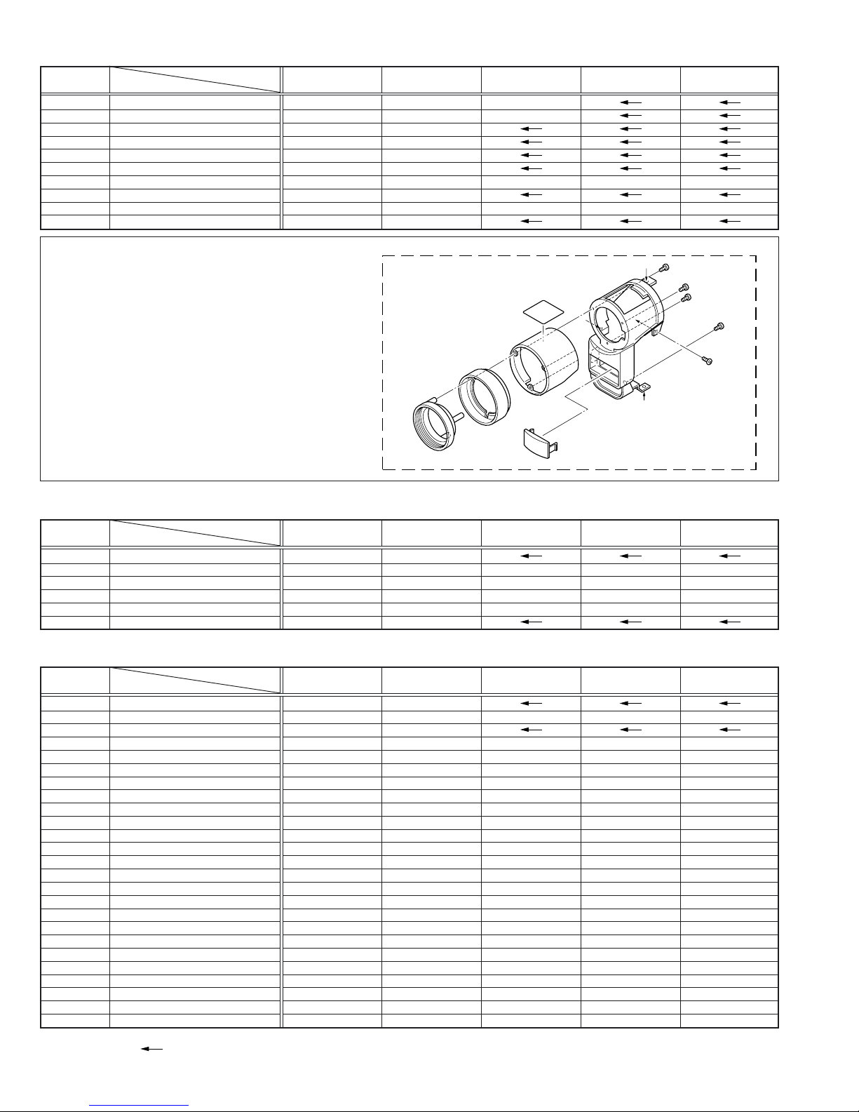
(CAMERA SECTION AND BOARD ASSEMBLY). . . . . . . . . . . . . . . . . . . . . . . . . . . . . . . . . . . . . . . . . . . . . . . . . .1-13
2.6 EMERGENCY DISPLAY . . . . . . . . . . . . . . . . . . . . . . . . . . . . . . . . . . . . . . . . . . . . . . . . . . . . . . . . . . . . . . . . . . . . .1-14
2.7 AUTOMATIC DEMONSTRATION . . . . . . . . . . . . . . . . . . . . . . . . . . . . . . . . . . . . . . . . . . . . . . . . . . . . . . . . . . . . .1-14
2.8 TAKE OUT CASSETTE TAPE . . . . . . . . . . . . . . . . . . . . . . . . . . . . . . . . . . . . . . . . . . . . . . . . . . . . . . . . . . . . . . . .1-16
2.9 SERVICE NOTE . . . . . . . . . . . . . . . . . . . . . . . . . . . . . . . . . . . . . . . . . . . . . . . . . . . . . . . . . . . . . . . . . . . . . . . . . . .1-17
3 ADJUSTMENT . . . . . . . . . . . . . . . . . . . . . . . . . . . . . . . . . . . . . . . . . . . . . . . . . . . . . . . . . . . . . . . . . . . . . . . . . . . . . . . . . .1-18
3.1 PREPARATION . . . . . . . . . . . . . . . . . . . . . . . . . . . . . . . . . . . . . . . . . . . . . . . . . . . . . . . . . . . . . . . . . . . . . . . . . . .1-18
3.2 TOOLS REQUIRED FOR ADJUSTMENT . . . . . . . . . . . . . . . . . . . . . . . . . . . . . . . . . . . . . . . . . . . . . . . . . . . . . . .1-18
3.3 MECHANISM ADJUSTMENT . . . . . . . . . . . . . . . . . . . . . . . . . . . . . . . . . . . . . . . . . . . . . . . . . . . . . . . . . . . . . . . . .1-20
3.4 ELECTRICAL ADJUSTMENT . . . . . . . . . . . . . . . . . . . . . . . . . . . . . . . . . . . . . . . . . . . . . . . . . . . . . . . . . . . . . . . . .1-23
GR-SX25EK GR-SX25EX GR-SX25EZ GR-SXM49EK GR-SXM49EX GR-SXM49EZ
LCD MONITOR NOT USED USED
SPEAKER NOT USED USED
CHARTS AND DIAGRAMS
BOARD INTERCONNECTIONS . . . . . . . . . . . . . . . . . . . . . . . . . . . . . . . . . . . . . . . . . . . . . . . . . . . . . . . . . . . . . . . . 2-2
CPU SCHEMATIC DIAGRAM. . . . . . . . . . . . . . . . . . . . . . . . . . . . . . . . . . . . . . . . . . . . . . . . . . . . . . . . . . . . . . . . . . 2-3
M.MDA SCHEMATIC DIAGRAM . . . . . . . . . . . . . . . . . . . . . . . . . . . . . . . . . . . . . . . . . . . . . . . . . . . . . . . . . . . . . . . 2-4
ASP SCHEMATIC DIAGRAM . . . . . . . . . . . . . . . . . . . . . . . . . . . . . . . . . . . . . . . . . . . . . . . . . . . . . . . . . . . . . . . . . . 2-5
DSP SCHEMATIC DIAGRAM. . . . . . . . . . . . . . . . . . . . . . . . . . . . . . . . . . . . . . . . . . . . . . . . . . . . . . . . . . . . . . . . . . 2-6
F/Z/I/MDA SCHEMATIC DIAGRAM . . . . . . . . . . . . . . . . . . . . . . . . . . . . . . . . . . . . . . . . . . . . . . . . . . . . . . . . . . . . . 2-7
V OUT SCHEMATIC DIAGRAM . . . . . . . . . . . . . . . . . . . . . . . . . . . . . . . . . . . . . . . . . . . . . . . . . . . . . . . . . . . . . . . . 2-8
TG/CDS SCHEMATIC DIAGRAM. . . . . . . . . . . . . . . . . . . . . . . . . . . . . . . . . . . . . . . . . . . . . . . . . . . . . . . . . . . . . . . 2-9
REG SCHEMATIC DIAGRAM . . . . . . . . . . . . . . . . . . . . . . . . . . . . . . . . . . . . . . . . . . . . . . . . . . . . . . . . . . . . . . . . 2-10
LCDSCHEMATIC DIAGRAM. . . . . . . . . . . . . . . . . . . . . . . . . . . . . . . . . . . . . . . . . . . . . . . . . . . . . . . . . . . . . . . . . 2-11
BW/VF SCHEMATIC DIAGRAM . . . . . . . . . . . . . . . . . . . . . . . . . . . . . . . . . . . . . . . . . . . . . . . . . . . . . . . . . . . . . . 2-12
JACK SCHEMATIC DIAGRAM . . . . . . . . . . . . . . . . . . . . . . . . . . . . . . . . . . . . . . . . . . . . . . . . . . . . . . . . . . . . . . . . 2-13
SPEAKER SCHEMATIC DIAGRAM . . . . . . . . . . . . . . . . . . . . . . . . . . . . . . . . . . . . . . . . . . . . . . . . . . . . . . . . . . . . 2-14
MONITOR SCHEMATIC DIAGRAM . . . . . . . . . . . . . . . . . . . . . . . . . . . . . . . . . . . . . . . . . . . . . . . . . . . . . . . . . . . . 2-15
E. VF CHEMATIC DIAGRAM . . . . . . . . . . . . . . . . . . . . . . . . . . . . . . . . . . . . . . . . . . . . . . . . . . . . . . . . . . . . . . . . . 2-16
TOP OPE UNIT, ZOOM UNIT, REAR UNIT AND SENSOR SCHEMATIC DIAGRAMS. . . . . . . . . . . . . . . . . . . . . 2-17
MAIN CIRCUIT BOARD . . . . . . . . . . . . . . . . . . . . . . . . . . . . . . . . . . . . . . . . . . . . . . . . . . . . . . . . . . . . . . . . . . . . . 2-18
COMPONENT PARTS LOCATION GUIDE <MAIN> YB10400-01-02. . . . . . . . . . . . . . . . . . . . . . . . . . . . . . . . . . 2-19
MAIN CIRCUIT BOARD . . . . . . . . . . . . . . . . . . . . . . . . . . . . . . . . . . . . . . . . . . . . . . . . . . . . . . . . . . . . . . . . . . . . . 2-21
MONITOR CIRCUIT BOARD . . . . . . . . . . . . . . . . . . . . . . . . . . . . . . . . . . . . . . . . . . . . . . . . . . . . . . . . . . . . . . . . . 2-22
CCD CIRCUIT BOARD . . . . . . . . . . . . . . . . . . . . . . . . . . . . . . . . . . . . . . . . . . . . . . . . . . . . . . . . . . . . . . . . . . . . . . 2-23
E.VF CIRCUIT BOARD. . . . . . . . . . . . . . . . . . . . . . . . . . . . . . . . . . . . . . . . . . . . . . . . . . . . . . . . . . . . . . . . . . . . . . 2-23
WAVEFORMS. . . . . . . . . . . . . . . . . . . . . . . . . . . . . . . . . . . . . . . . . . . . . . . . . . . . . . . . . . . . . . . . . . . . . . . . . . . . . 2-23
VOLTAGE CHARTS . . . . . . . . . . . . . . . . . . . . . . . . . . . . . . . . . . . . . . . . . . . . . . . . . . . . . . . . . . . . . . . . . . . . . . . . 2-24
POWER SYSTEM BLOCK DIAGRAM . . . . . . . . . . . . . . . . . . . . . . . . . . . . . . . . . . . . . . . . . . . . . . . . . . . . . . . . . . 2-25
CPU/MDA SYSTEM BLOCK DIAGRAM . . . . . . . . . . . . . . . . . . . . . . . . . . . . . . . . . . . . . . . . . . . . . . . . . . . . . . . . . 2-26
MONITOR SYSTEM BLOCK DIAGRAM . . . . . . . . . . . . . . . . . . . . . . . . . . . . . . . . . . . . . . . . . . . . . . . . . . . . . . . . 2-27
CAMERA AND Y/C SYSTEM BLOCK DIAGRAM . . . . . . . . . . . . . . . . . . . . . . . . . . . . . . . . . . . . . . . . . . . . . . . . . 2-28
CAMERA AND Y/C SYSTEM BLOCK DIAGRAM . . . . . . . . . . . . . . . . . . . . . . . . . . . . . . . . . . . . . . . . . . . . . . . . . 2-29
PARTS LIST
1 PACKING AND ACCESSORY ASSEMBLY <M1> . . . . . . . . . . . . . . . . . . . . . . . . . . . . . . . . . . . . . . . . . . . . . . . . . . 3-1
2 FINAL ASSEMBLY <M2> . . . . . . . . . . . . . . . . . . . . . . . . . . . . . . . . . . . . . . . . . . . . . . . . . . . . . . . . . . . . . . . . . . . . . 3-2
3 MECHANISM ASSEMBLY <M3> . . . . . . . . . . . . . . . . . . . . . . . . . . . . . . . . . . . . . . . . . . . . . . . . . . . . . . . . . . . . . . . 3-5
4 ELECTRONIC VIEWFINDER ASSEMBLY <M4> . . . . . . . . . . . . . . . . . . . . . . . . . . . . . . . . . . . . . . . . . . . . . . . . . . . 3-7
5 MONITOR ASSEMBLY <M5>. . . . . . . . . . . . . . . . . . . . . . . . . . . . . . . . . . . . . . . . . . . . . . . . . . . . . . . . . . . . . . . . . . 3-8
6 ELECTRICAL PARTS LIST
MAIN BOARD ASSEMBLY <01> . . . . . . . . . . . . . . . . . . . . . . . . . . . . . . . . . . . . . . . . . . . . . . . . . . . . . . . . . . . . . . . 3-9
CCD BOARD ASSEMBLY <02> . . . . . . . . . . . . . . . . . . . . . . . . . . . . . . . . . . . . . . . . . . . . . . . . . . . . . . . . . . . . . . . 3-16
MONITOR BOARD ASSEMBLY <07> . . . . . . . . . . . . . . . . . . . . . . . . . . . . . . . . . . . . . . . . . . . . . . . . . . . . . . . . . . 3-16
E.VF BOARD ASSEMBLY <60>. . . . . . . . . . . . . . . . . . . . . . . . . . . . . . . . . . . . . . . . . . . . . . . . . . . . . . . . . . . . . . . 3-17
Instructions

1-4 (No.86712)
1.1.2 Safety Check after Servicing
Examine the area surrounding the repaired location for damage
or deterioration. Observe that screws, parts and wires have been
returned to original positions, Afterwards, perform the following
tests and confirm the specified values in order to verify compli-
ance with safety standards.
(1) Insulation resistance test
Confirm the specified insulation resistance or greater be-
tween power cord plug prongs and externally exposed
parts of the set (RF terminals, antenna terminals, video and
audio input and output terminals, microphone jacks, ear-
phone jacks, etc.).
See table 1 below.
(2) Dielectric strength test
Confirm specified dielectric strength or greater between
power cord plug prongs and exposed accessible parts of
the set (RF terminals, antenna terminals, video and audio
input and output terminals, microphone jacks, earphone
jacks, etc.). See Fig.11 below.
(3) Clearance distance
When replacing primary circuit components, confirm spec-
ified clearance distance (d), (d') between soldered termi-
nals, and between terminals and surrounding metallic
parts. See Fig.11 below.
Fig.8
(4) Leakage current test
Confirm specified or lower leakage current between earth
ground/power cord plug prongs and externally exposed ac-
cessible parts (RF terminals, antenna terminals, video and
audio input and output terminals, microphone jacks, ear-
phone jacks, etc.).
Measuring Method : (Power ON)
Insert load Z between earth ground/power cord plug
prongs and externally exposed accessible parts. Use an
AC voltmeter to measure across both terminals of load Z.
See Fig.9 and following Fig12.
Fig.9
(5) Grounding (Class 1 model only)
Confirm specified or lower grounding impedance between
earth pin in AC inlet and externally exposed accessible
parts (Video in, Video out, Audio in, Audio out or Fixing
screw etc.).
Measuring Method:
Connect milli ohm meter between earth pin in AC inlet and
exposed accessible parts. See Fig.10 and grounding spec-
ifications.
Fig.10
Fig.11
Fig.12
NOTE :
These tables are unofficial and for reference only. Be sure to confirm the precise values for your particular country and locality.
ab
c
V
A
Externally
exposed
accessible part
Z

(No.86712)1-5
SECTION 2
SPECIFIC SERVICE INSTRUCTIONS
2.1 BEFORE ASSEMBLY AND DISASSEMBLY
2.1.1 Precautions
1. Be sure to disconnect the power supply unit prior to mount-
ing and soldering of parts.
2. Prior to removing a component part that needs to disconnect
its connector(s) and its screw(s), first disconnect the wire(s)
from the connector(s), and then remove the screw(s).
3. When connecting/disconnecting wires, pay enough atten-
tion not to damage the connectors.
4. Be careful in removing or handling the part to which some
spacer or shield is attached for reinforcement or insulation.
5. When replacing chip parts (especially IC parts), first remove
the solder completely to prevent peeling of the pattern.
6. Tighten screws properly during the procedures. Unless
specified otherwise, tighten screws at a torque of
0.196N•m (2.0kgf•cm).
2.1.2 Assembly and disassembly
(1) Order of steps in Procedure
When reassembling, preform the step(s) in the reverse
order. These numbers are also used as the identification
(location) No. of parts Figures.
(2) Part to be removed or installed.
(3) Fig. No. showing Procedure or Part Location.
(4) Identification of part to be removed, unhooked, unlocked,
released, unplugged, unclamped or unsoldered.
(5) Adjustment information for installation.
2.1.3 Destination of connectors
2.1.4 Disconnection of connectors (Wires)
Pull both ends of the connector in the arrow direction, remove the
lock and disconnect the flat wire.
Fig.2-1-1
Extend the locks in the direction of the arrow for unlocking and
then pull out the wire. After removing the wire, immediately re-
store the locks to their original positions because the locks are
apt to come off the connector.
Fig.2-1-2
2.1.5 Tools required for disassembly and assembly
Fig.2-1-3
1.Torque driver
Be sure to use to fastening the mechanism and exterior parts
because those parts must strictly be controlled for tightening
torque.
2.Bit
This bit is slightly longer than those set in conventional torque
drivers.
3.Cleaning cloth
Recommended cleaning cloth to wipe down the video heads,
mechanism (tape transport system), optical lens surface.
C = CABINET
D = CAMERA AND BOARD ASSEMBLY
P=Spring
W=Washer
S=Screw
* = Unhook, unlock, release, unplug or unsolder.
2(S3) = 2 Screws (S3)
CN = Connector
LOWER CASE ASSEMBLY
B/W VF ASSEMBLY
TOP OPE UNIT
CASE COVER(S) ASSEMBLY
CASE COVER(M) ASSEMBLY
Fig.C1
Fig.C2
8(S1),CN1a,b,c
3(S2)
CN3,L3a,2(L3b)
(S4),2(L4)
-
-
-
-
[1]
[2]
[3]
[4]
STEP
No. PART NOTE
Fig.
No. POINT
(4) (5)(2) (3)(1)
[Example]
CN1a MAIN CN27 2
CONN.
No. Pin No.
CONNECTOR
Remove the parts marked in .
[Example]
Two kinds of double-arrows in connection tables respectively
show kinds of connector/wires.
: Flat wire
: Wire
-
SPEAKER
Connector
Flat wire
Connector
Flat wire
Torque driver
YTU94088
12
Bit
YTU94088-003
3
Cleaning cloth
KSMM-01

1-6 (No.86712)
2.2 ASSEMBLY AND DISASSEMBLY OF CABINET PARTS
2.2.1 Disassembly flow chart
This flowchart indicates the disassembly step for the cabinet
parts and board assembly in order to gain access to item(s) to be
serviced. When reassembling, perform the step(s) in reverse or-
der.
2.2.2 Disassembly method
NOTE 5 :
Take care not to break or damage the FRAME.
NOTE 7a :
Take care not to cut the FPC wire.
NOTE 7b :
Insert and attach the SHEET(FPC) between the MONITOR
FPC and the UPPER CASE(M)ASSEMBLY.
NOTE 7c :
Attachment of the FPC
NOTE 7d :
For disassembly of the MONITOR ASSEMBLY, refer to 2.4
ASSEMBLY AND DISASSEMBLY OF [7]MONITOR ASSEM-
BLY (CABINET PARTS).
NOTE 8a :
Take care not to damage the OP BLOCK ASSEMBLY when
and after the FRONT CASE ASSEMBLY is removed.
NOTE 8b :
Attachment of the WIRE
NOTE 11 :
There are two types of FRONT FRAME ASSEMBLY.
The two types of the FRONT FRAME ASSEMBLY can be dis-
tinguished from each other by their shape.
TYPE B consists of the two parts, namely the tape guide and
the torsion spring.
In exchanging the FRONT FRAME ASSEMBLY, TYPE A can
be exchanged to TYPE B, but TYPE B cannot be exchanged
to TYPE A.
As for the part number, refer to the parts list.
[1]
B/W VF ASSEMBLY
[2]
TOP OPE UNIT
[3]
CASE COVER(S) ASSEMBLY
CASE COVER(M) ASSEMBLY
[4]
[4]
UPPER CASE (M) ASSEMBLY
Inc. MONITOR ASSEMBLY
UPPER CASE (S) ASSEMBLY
[5]
[5]
COVER (UPPER/M) ASSEMBLY
[6]
[7]
FRONT COVER ASSEMBLY
Inc. DC LIGHT,MIC
[8]
MONITOR ASSEMBLY
DC LIGHT ASSEMBLY
[9]
[10]
MIC
[11]
FRONT FRAME SA
LOWER CASE ASSEMBLY
NOTE:
MONITOR MODEL ONLY
LOWER CASE ASSEMBLY
B/W VF ASSEMBLY
TOP OPE UNIT
CASE COVER(S) ASSEMBLY
CASE COVER(M) ASSEMBLY
UPPER CASE (S) ASSEMBLY
UPPER CASE (M) ASSEMBLY
Inc. MONITOR ASSEMBLY
COVER (UPPER/M) ASSEMBLY
MONITOR ASSEMBLY
FRONT COVER ASSEMBLY
Inc. DC LIGHT,MIC
DC LIGHT ASSEMBLY
MIC
FRONT FRAME SA
Fig.C1
Fig.C2
Fig.C3
Fig.C4
Fig.C5
8(S1),CN1a,b,c
3(S2)
CN3,L3a,2(L3b)
(S4),2(L4)
6(S5a),(S5b)
CN5,6(S5a),(S5b)
3(S6),2(L6)
S7a,L7,SHEET(FPC),2(S7b)
CN8a,CN8b,(S8),L8a,L8b
2(L9)
S10
2(S11)
-
-
-
-
NOTE 5
-
NOTE 7a,b,c,d
NOTE 8a,b
-
-
NOTE 11
[1]
[2]
[3]
[4]
[5]
[6]
[7]
[8]
[9]
[10]
[11]
CN1a
CN1b
CN1c
CN3
CN5
CN8a
CN8b
MAIN CN27
MAIN CN13
MAIN CN12
MAIN CN18
MAIN CN16
MAIN CN6
MAIN CN8
2
14
3
13
25
2
2
STEP
No. PART
CONN.
No. Pin No.
CONNECTOR
NOTE
Fig.
No. POINT
Remove the parts marked in .
-
-
-
-
-
-
SPEAKER
ZOOM UNIT
B/W VF ASSEMBLY
TOP OPE UNIT
MONITOR ASSEMBLY
DC LIGHT
MIC

(No.86712)1-7
Fig.C1
Fig.C2
t
q
u
p
r
FG
y
x
E
s1
v
z
w
q
p
r
s1
E
[2]
[1]
x
t
u
E
G
z
y
D
F
vw
D
L3b
L3a
[3]
CN1c
CN1b
CN1a
CN3
3
(
S1
)
9
(
S2
)
10
(
S2
)
11
(
S2
)
1
(
S1
)
2
(
S1
)
8
(
S1
)
7
(
S1
)
4
(
S1
)
5
(
S1
)
6
(
S1
)
aa
12
(S4)
L4
[4]
[4]
aa
aa
<MONITOR MODEL>
<SHOOTING MODEL>

1-8 (No.86712)
Fig.C3
Fig.C4
j
cdk
C
<MONITOR MODEL>
<SHOOTING MODEL>
i
j
k
h
l
k
n
g
g
i
h
j
k
n
C
m
m
m
n
g
14
(S5a)
15
(S5a)
16
(S5a)
17
(S5a)
18
(S5a)
19
(S5b)
14
(S5a)
17
(S5a)
18
(S5a)
15
(S5a)
16
(S5a) 13
(S5a)
CN5
<NOTE 5>
[5]
<NOTE 5>
[5]
e
d
c
f
e
fd
c
AS FOR PUSH SW, DON'T BE
BROKEN AND DON'T FLOAT .
(SEE AND CHECK SW AFTER
ATTACHING FPC.)
[7]
<NOTE 7d>
[6]
L6
20
(S6)
24
(S7b)
25
(S7b)
21
(S6)
22
(S6)
L7
UPPER CASE(M)ASSEMBLY
<NOTE 7b>
SHEET(FPC)
<NOTE 7c>
DO NOT MAKE FPC
SLACKEN IN THIS PART.
PROCESSED
THROUGH THIS PART.
INSTALL THE RAINFORCEMENT
BOARD WITH MONITOR OPENED .
( FOR THE DAMAGE PREVENTION
OF PUSH SWITCH .)
<MONITOR MODEL>
FPC
<NOTE 7a>
23
(S7a)

(No.86712)1-9
Fig.C5
[10]
L9
[9]
27
(S10)
B
A
b
b
a
a
B
c
A
c
[11]
CN8b
CN8a
[8]
L8b
26
(S8)
<NOTE 8a>
OP BLOCK ASSEMBLY
<NOTE 11>
L8a
<NOTE 8b>
SCREWING SEQUENCE
SHOULD BE IN ORDER
HERE FIRST AND OTHERS .
LIGHT WIRE
DO NOT OBSTRUCT
THE RECEIVING
PART OF SENSOR
BY WIRE .
PASS THE WIRE
OUTSIDE OF
THIS BOSS .
MIC WIRE
PASS THE WIRE
BETWEEN
THESE BOSSES.
SHIELD SHEET
SHOULD BE PUTTED SHIELD
PLATE BETWEEN FRAME TO MECHA .
28
(S11)
29
(S11)
0.118N.m (1.2kgf.cm)
<NOTE 11>
TYPE A TYPE B

1-10 (No.86712)
2.3 ASSEMBLY AND DISASSEMBLY OF CAMERA SECTION AND BOARD ASSEMBLY
2.3.1 Disassembly flow chart
This flowchart indicates the disassembly step for the cabinet
parts and board assembly in order to gain access to item(s) to be
serviced. When reassembling, perform the step(s) in reverse or-
der.
2.3.2 Disassembly method
NOTE 3 :
For disassembly of the CCD BOARD ASSEMBLY, refer to 2.5
ASSEMBLY AND DISASSEMBLY OF [2]OP BLOCK ASSEM-
BLY CCD BOARD ASSEMBLY (CAMERA SECTION AND
BOARD ASSEMBLY).
NOTE 4 :
When attaching the MECHANISM ASSEMBLY to S.CASE
(MAIN), pull out the FPC CABLE not to be inserted between
the MECHANISM ASSEMBLY and S.CASE (MAIN).
[4]
MECHANISM
ASSEMBLY
[5]
REAR BOARD ASSEMBLY
MAIN BOARD ASSEMBLY
[2]
[1]
OP BLOCK
ASSEMBLY
[3]
CCD BOARD ASSEMBLY
NOTE:
Please see Service Manual No. 86700 (MECHANISM ASSY).
MAIN BOARD ASSEMBLY
OP BLOCK ASSEMBLY
CCD BOARD ASSEMBLY
MECHANISM ASSEMBLY
REAR BOARD ASSEMBLY
Fig.D1
Fig.D2
Fig.D3
Fig.D4
CN1a,b,c,d,e,f,g,h,SHIELD
2(S1),CN1j
2(S2)
(S4a),(S4b),L4
SHIELD CASE(MAIN)
2(S4c),(S4d)
2(S5)
-
-
NOTE 3
NOTE 4
-
[1]
[2]
[3]
[4]
[5]
STEP
No. PART NOTE
Fig.
No. POINT
CN1a
CN1b
CN1c
CN1d
CN1e
CN1f
CN1g
CN1h
CN1j
MAIN CN15
MAIN CN4
MAIN CN1
MAIN CN5
MAIN CN2
MAIN CN3
MAIN CN7
MAIN CN22
MAIN CN28
-
-
-
-
-
-
-
CN5301
-
24
2
10
11
14
18
11
14
10
CONN.
No. Pin No.
CONNECTOR
Remove the parts marked in .
OP BLOCK
ASSEMBLY
LOADING MOTOR
DRUM MOTOR
HEAD(VIDEO,FLY.E)
SENSOR
CAPSTAN MOTOR
A/C HEAD
CCD
REAR UNIT

(No.86712)1-11
Fig.D1
Fig.D2
Fig.D3
Fig.D4
A2 F2
G2
D2
E2
[1]
B2
C2
J
A2
B2
C2
E2
D2
F2
G2
J
CN1e
SHIELD
CN1b
CN1a
1
(S1)
2
(S1)
CN1h
CN1g
CN1f
CN1j CN1d CN1c
h
j
j
h
[3]
<NOTE 3>
[2]
3
(S2)
4
(S2)
g
c
d
c
d
e
G1
G2
f
g
7
(S4c)
L4
<NOTE 4>
FRAME ASSEMBLY
6
(S4b)
5
(S4a)
8
(S4c)
[4]
9
(S4d)
SHIELD
CASE
(MAIN)
b
b
a
a
[5]
FRAME
ASSEMBLY
11
(S5)
10
(S5)

1-12 (No.86712)
2.4 ASSEMBLY AND DISASSEMBLY OF [7]MONITOR ASSEMBLY (CABINET PARTS)
2.4.1 Disassembly of MONITOR ASSEMBLY
NOTE :
Be careful not to soil or scratch the monitor screen through the
disassembly/assembly work.
(1) While removing the three screws 1 to 3 in numerical order
and disengaging the two hooks (L7a and L7b) in alphabet-
ical order, remove the MONITOR COVER ASSEMBLY.
NOTE 7a :
After removing the MONITOR COVER ASSEMBLY, be
careful not to damage the FPC and the connector be-
cause the MONI. HINGE ASSEMBLY moves very easily.
(2) Unlock the connector 7a and then remove the FPC while
lifting the MONI. HINGE ASSEMBLY upwards to remove it
together with the FPC.
NOTE 7b :
When removing the FPC, unlock the connector first and
then lift the MONI. HINGE ASSEMBLY upwards.
Accordingly, the FPC is removed together with the
MONI.HINGE ASSEMBLY.
(3) Unsolder the two soldered parts (SD7).
NOTE 7c :
When removing the MONITOR BOARD ASSEMBLY and
the BACKLIGHT together, it is not necessary to unsolder
the two soldered parts (SD7).
NOTE 7d :
It depends on the inch size of the monitor assembly
whether the backlight is supplied as an assembly or as
separated parts.
In replacing the backlight assembly, see the Parts List.
(4) Unlock the connector 7b, and disconnect the FPC from the
connector 7b.
(5) Disconnect the FPC from MONITOR CASE ASSEMBLY.
(6) Remove the screw (4), and remove the MONITOR BOARD
ASSEMBLY while lifting the side of MONITOR BOARD AS-
SEMBLY which has been attached with screw (4) upwards.
(7) Remove the BACKLIGHT and DIFF SHEET in this order.
(8) Remove the LCD FRAME&LCD MODULE while disengag-
ing L7e and L7f at the both sides of MONITOR CASE AS-
SEMBLY.
(9) Remove the S.CASE.
Fig.2-4-1
D1
C1
F1
F1
C1
LCD FRAME &
LCD MODULE
BACK LIGHT
ASSEMBLY
S.CASE
L7d
<NOTE 7c>
SD7
1
(S7a)
4
(S7a)
L7b
L7a
<NOTE 7b>
CN7a
<NOTE 7b>
CN7b
<NOTE 7d>
L7c
2
(S7b)
3
(S7b)
L7e
L7f
B1
B1
A1
A1
D1
MONITOR CASE ASSEMBLY
MONITOR COVER
ASSEMBLY
MONI. HINGE
ASSEMBLY
MONITOR BOARD
ASSEMBLY
DIFF SHEET
SHOULD PUT THIS
PART AT RIGHT SIDE .
E1
E1

(No.86712)1-13
2.5 ASSEMBLY AND DISASSEMBLY OF [2]OP BLOCK ASSEMBLY
CCD BOARD ASSEMBLY (CAMERA SECTION AND BOARD ASSEMBLY)
2.5.1 Precautions
(1) Take care in handling the CCD IMAGE SENSOR, OP LPF
and lens components when performing maintenance etc.,
especially with regard to surface contamination, attached
dust or scratching. If fingerprints are present on the surface
they should be wiped away using either a silicon paper,
clean chamois or the cleaning cloth.
(2) The CCD IMAGE SENSOR may have been shipped with a
protective sheet attached to the transmitting glass. When
replacing the CCD IMAGE SENSOR, do not peel off this
sheet from the new part until immediately before it is
mounted in the OP BLOCK ASSEMBLY.
(3) The orientation of the OP LPF is an important factor for
installation. If there is some marking on the OP LPF, be
sure to note it down before removing and to reassemble it
very carefully as it was referring to the marking.
2.5.2 Disassembly of CCD BOARD ASSEMBLY and CCD
BASE ASSEMBLY
(1) Unsolder the CCD BOARD ASSEMBLY by the 14 points
(SD2) and then remove it.
(2) Remove the two screws (1, 2) and remove the CCD BASE
ASSEMBLY.
(3) Remove the SPACER.
(4) Remove the SHEET.
(5) Remove the OP LPF.
2.5.3 Assembly of CCD BASE ASSEMBLY and CCD
BOARD ASSEMBLY
(1) Set the OP LPF to the OP BLOCK ASSEMBLY so that the
OP side touches the OP BLOCK ASSEMBLY.
NOTE 2a:
Pay careful attention to the orientation of the OP LPF.
(2) Set the SHEET to the OP LPF not to come off the right
position.
(3) Attach the SPACER to the OP BLOCK ASSEMBLY.
(4) Fasten them together with the two screws (1, 2).
(5) Set the CCD BOARD ASSEMBLY in the CCD BASE
ASSEMBLY, and then solder it by the 14 points (SD2).
2.5.4 Replacement of service repair parts
The service repair parts for the OP BLOCK ASSEMBLY are as
listed below.
Before replacement of these parts, remove the BRACKET (OP
BLOCK ASSEMBLY) as required.
Take special care not to disconnect any of the FPC wires or
cause any damage due to soldering (excessive heating).
(1) FOCUS MOTOR
(2) ZOOM MOTOR
(3) IRIS MOTOR UNIT
NOTE 2b:
When replacing the FOCUS MOTOR or the ZOOM MOTOR,
solder the FPC at a space of about 1 mm above the terminal
pin.
NOTE 2c:
The IRIS MOTOR UNIT includes the FPC ASSEMBLY and
two sensors.
Fig.2-5-1
2
(S2a)
1
(S2a)
(SD2)
OP
side
CCD
side
Blue
<NOTE 2a>
OP LPF
OP BLOCK
ZOOM MOTOR
<NOTE 2b>
SHEET
OP LPF
SPACER
CCD BASE ASSEMBLY
CCD BAORD
ASSEMBLY
SENSOR
IRIS MOTOR UNIT
<NOTE 2b, c>
FOCUS MOTOR
<NOTE 2b>
0.078N.m (0.8kgf.cm)
0.118N.m (1.2kgf.cm)
4
(S2b)
3
(S2b)
6
(S2b)
5
(S2b)
10
(S2c)
11
(S2c)
9
(S2c)
7
(S2c)
8
(S2c)

1-14 (No.86712)
2.6 EMERGENCY DISPLAY
Whenever some abnormal signal is input to the mechacon CPU,
an error number (E01, as an example) is displayed in the elec-
tronic view finder. In every error status, such the message as
shown below alternately appear over and over.
• In an emergency mode, all operations except turning on/off the
POWER switch are ineffectual.
(PAL)
2.7 AUTOMATIC DEMONSTRATION
Automatic Demonstration takes place when “DEMO MODE” is
set to “ON” (factory-preset).
(1) Available when the Power Switch is set to “A” or “M” while
pressing down the Lock Button located on the switch.
(2) Performing any operation during the demonstration stops
the demonstration temporarily. If no operation is performed
for more than 1 minute after that, the demonstration will
resume.
(3) “DEMO MODE” remains “ON” even if the camcorder power
is turned off.
(4) To cancel Automatic Demonstration, set the Power Switch
to “M” and press the MENU Wheel in while the demo is in
progress. This takes you directly to the demo mode’s Set-
ting Menu (so you will not have to go through the main
Menu Screen). Rotate the MENU Wheel to select “OFF”
and press it.
NOTE:
• When a tape whose Erase Protection tab is in the position
that allows recording is loaded in the
camcorder, demonstration is not available.
• If you do not detach the Lens Cap, you cannot see the actual
changes of the Automatic Demonstration activated on the
LCD monitor* or viewfinder.
* Applicable models only.
Fig.2-7-1
Example (in case of the error number E01):
E01
UNIT IN
SAFEGUARD MODE
E01
REMOVE AND
REATTACH BATTERY
E. VF Symptom Mode when observed
E07 Short circuit of capstan MDA Power ON
E06 CAPSTAN FG input absent CAPSTAN rotation
E04 DRUM FG input absent DRUM rotation
E03 SUPPLY REEL FG input absent REC, PLAY, SEARCH, FF/REW
E02 Mode control motor rotates for more than 7.5 sec UNLOADING without shift to next
mode.
UNLOADING
E01 Mode control motor rotates for more than 7.5 sec LOADING without shift to next mode. LOADING
E00 Overtime the programming transaction REC, PLAY
MENU Wheel
Power Switch
Lock Button

(No.86712)1-15
2.7.1 Operation procedure
Fig.2-7-2
2.7.2 Flow chart
NOTE:
When demonstration is performed, some of the following func-
tions that a model does not have are omitted.
Fig.2-7-3
R
D
N
E
.
E
C
X
Z
T
M
O
S
O
O
Y
D
M
S
E
TEM ME
S
N
P
U
TO S
C
Y
A
S
M
T
E
E
R
M
A
M
M
E
E
N
N
U
U
TITLE MOVIE
EXPOSURE AUTO
M. W. B. AUTO
R
I
T
D
D
T
E
N
E
A
E
R
O
C
T
L
T
M
E
.
E
E
O
T
C
T
/
U
S
A
I
T
M
T
M
R
Y
M
M
I
A
I
O
N
S
E
E
M
C
M
D
T
R
E
R
E
E
E
A
O
M
M
M
E
E
N
O
O
O
O
N
U
F
F
F
F
U
F
OSDOU T P UT O N
F
F
F
OFF
Display 1
Display 2
Display 4
Display 3
Refer to Fig. 2-7-3.
While the DEMONSTRATION
mode is activated, a word of
DEMONSTRATION is appearing
on the screen scrolling from right
to left.
DEMO MODE
OFF
ON
EXIT
R
I
T
D
D
T
E
N
E
A
E
R
O
C
T
L
T
M
E
.
E
E
O
T
C
T
/
U
S
A
I
T
M
T
M
R
Y
M
M
I
A
I
O
N
S
E
E
M
C
M
D
T
R
E
R
E
E
E
A
O
M
M
M
E
E
N
O
O
O
O
N
U
F
F
F
N
U
F
F
F
OSDOU T P UT O N
1. Set the Power Switch to turn on
the "M".
Press the MENU Wheel once.
The first page of the DISPLAY
appears on the LCD monitor (or in
the viewfinder).
Press the MENU Wheel once.
The second page of the DISPLAY
appears on the LCD monitor (or in
the viewfinder).
2. Press the MENU Wheel once.
The third page of the DISPLAY
appears on the LCD monitor (or in
the viewfinder).
3. Turn the MENU Wheel in the
direction ofthe arrow to set the
cursor at "DEMO MODE".
Then, press the MENU Wheel
once.
The third page the DEMO
MODE appearson the LCD
monitor (or in the viewfinder).
4. Turn the MENU Wheel in the
direction ofthe arrow to set the
cursor at "ON".
Then, press the MENU Wheel
once.
The fourth page of the DISPLAY
appears on the LCD monitor (or in
the viewfinder).
("DEMO MODE" is switched "ON"
from "OFF" status.)
5. Press the MENU Wheel once.
The camcorder automatically
enter the DEMONSTRATION
mode and it repeats
demonstration operation.
While the camcorder is performing
demonstration, all operations
except turning on/off the Power
Switch are ineffectual.
1. TITLE CALL and FUTURE
2. EASY PC CONNECTION
3. CREATE IMAGES & E-MAIL
4. NIGHT-SCOPE OFF
5. NIGHT-SCOPE ON
6. VHS
7. S-VHS (For S-VHS MODEL ONLY)
8. SNAP SHOT
9. PROGRAM AE FOG
10. PROGRAM AE ND EFFECT
11. FADE/WIPE BLACK
12. FADE/WIPE MOSAIC
13. FADE/WIPE SHUTTER
14. FADE/WIPE SLIDE
15. FADE/WIPE DOOR
16. FADE/WIPE CORNER
17. FADE/WIPE WINDOW
18. DIGITAL EFFECT NEGA/POSI
19. DIGITAL EFFECT STRETCH
20. DIGITAL EFFECT MOSAIC
21. DIGITAL EFFECT SEPIA
22. DIGITAL EFFECT B/W
23. DIGITAL EFFECT B.FILTER
24. DIGITAL EFFECT R.FILTER
25. DIGITAL EFFECT SOLARI
26. DIGITAL EFFECT STROBE
27. DIGITAL EFFECT CLASSIC
28. DIGITAL EFFECT VIDEO ECHO
29. WIDE OFF
30. WIDE ON
31. WIDE OFF
32. P.STABILIZER OFF
33. P.STABILIZER ON
34. P.STABILIZER OFF
35. P.STABILIZER ON

1-16 (No.86712)
2.8 TAKE OUT CASSETTE TAPE
In the event that the set enters the emergency mode as it is
loaded with a cassette tape and the cassette tape cannot be
ejected with the EJECT button, manually, take it out of the set
according to the following procedure.
NOTE :
• If the mechanism comes into the unloading mode as the cas-
sette tape is not held by hand, it results in tape damage.
(1) Disconnect the set from the power source.
(2) Remove the LOWER CASE ASSEMBLY and TOP OPE
UNIT (see Fig.C1, page 6).
(3) Connect a jumper wire to each pole of the LOADING
MOTOR as shown by the magnified view (Fig. 2-8-1).
(4) While holding down the cassette housing by hand, con-
nect the jumper wires to a battery to run the mechanism
to the EJECT position four unloading. If this unloading
operation is performed as the cassette housing is not
held down by hand, the front lid of the cassette may dam-
age the tape when it is ejected.
(5) For taking in the slack of the tape, run the mechanism to
the EJECT position as the front lid of the cassette is left
open, and turn the TAKE-UP GEAR in the forward direc-
tion to wind up the tape. After confirming that the tape
has completely been wound up and the supply reel is
idling, take the cassette tape out of the cassette housing.
Fig.2-8-1
MAGNIFIED VIEW
(DC1.5V)
b
BATTERY
TAKE-UP GEAR

(No.86712)1-17
2.9 SERVICE NOTE
Use the following chart to manage screws
Symbol No. [2] [3] [4] [5]
Removing order of screw 1 2 3 4 5 6 7 8 9 10 11 - 12 13 14 15 16 17 18 19
Place to stick screw -
-
Screw tightening torque
Reference drawing
Fig.C2
Fig.C3
Symbol No. [6] [7]
[7] [2]
[8] [9] [10]
Removing order of screw 20 21 22 23 24 25 26 -27 28 29
Place to stick screw -
-
-
Screw tightening torque
Reference drawing
Symbol No.
Symbol No. Symbol No.
[4]
Removing order of screw 1234567891011
Place to stick screw
Screw tightening torque
Reference drawing Fig.D3
<2.5 OP BLOCK ASSEMBLY>
Removing order of screw 1 2 3 4 Removing order of screw 1 2 3 4 5 6 7 8 9 10 11
Place to stick screw Place to stick screw
Screw tightening torque Screw tightening torque
Reference drawing Reference drawing
<NOTE>
Fig.2-5-1
Fig.C1
Fig.D1 Fig.D2 Fig.D4
[5]
Fig.2-4-1
[1]
Fig.C4 Fig.C5
<2.4 MONITOR ASSEMBLY>
<2.3 CAMERA SECTION AND BOARD ASSEMBLY>
<2.2 CABINET PARTS>
[11]
[1] [2]/[3]
**
This manual suits for next models
15
Table of contents
Other JVC Camcorder manuals

JVC
JVC GR-AXM4U User manual

JVC
JVC GR-D241AC User manual

JVC
JVC GR-DA30UC Administrator Guide

JVC
JVC GR-AX11EG User manual

JVC
JVC GR-AX958EG User manual

JVC
JVC GR-DVM828 User manual

JVC
JVC GR-AX750 User manual

JVC
JVC Everio GZ-GX1 Operating and maintenance manual

JVC
JVC GR-DVL715 User manual

JVC
JVC Digital Media Camera GZ-MC500E/EK User manual