2
When attaching Network Pack KA-DV300 to DV Camcorder GY-DV300, network related menus are added to the GY-DV300 menu
screen.
This User’s Guide explains settings for the network related menus, operation for recording streaming data to a CF (Compact Flash)
memory card and operation for sending streaming data using a LAN card. When a LAN card is connected, menu screen settings for the
Network Pack and GY-DV300 can be operated from your PC.
Contents
Introduction
Inserting/removing CF memory card/LAN card ............................................................................................................................... 3
LCD screen/viewfinder screen ......................................................................................................................................................... 4
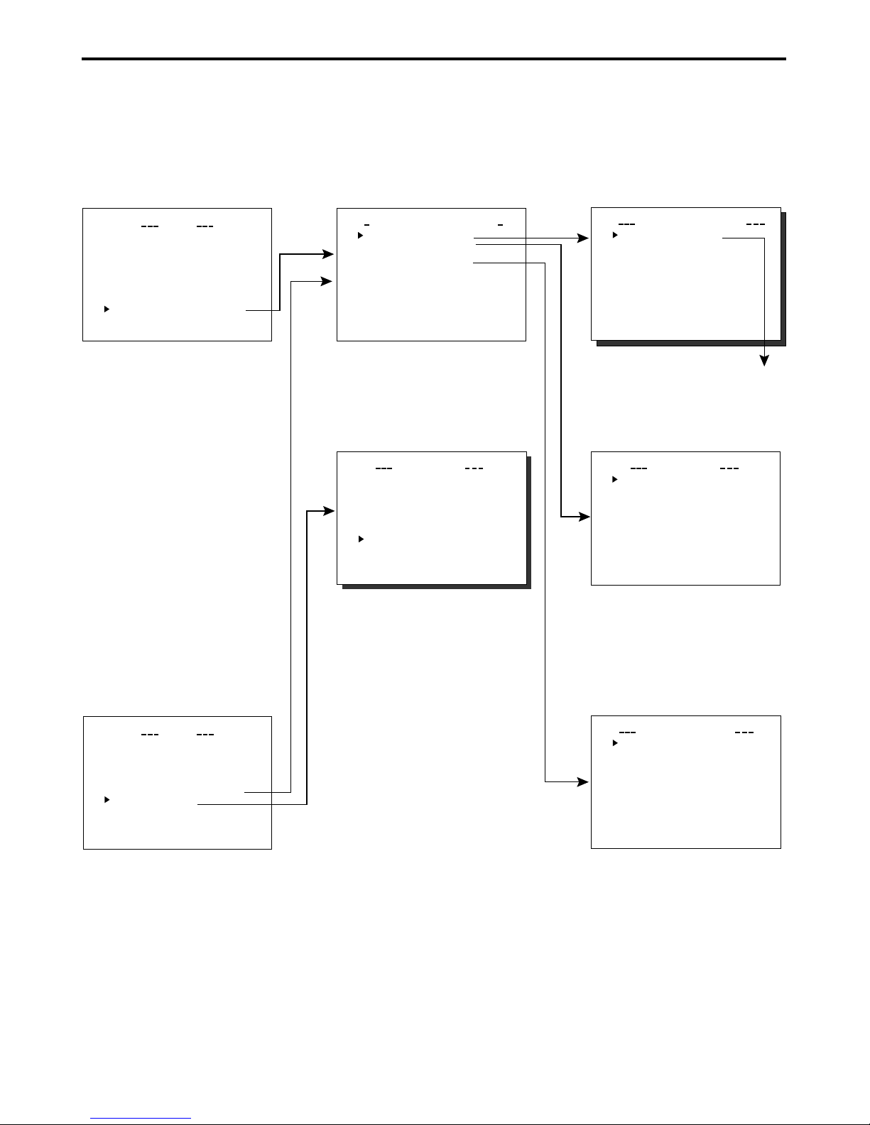
Menu screen
Menu screen structure ..................................................................................................................................................................... 5
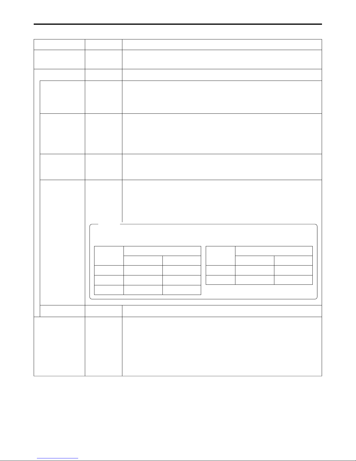
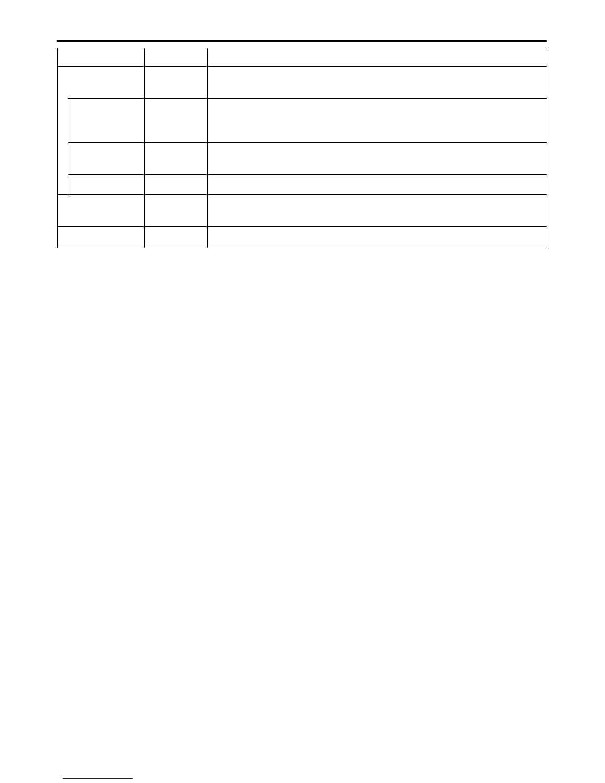
NETWORK PACK CONFIG menu screen items ............................................................................................................................... 6
Setting the NETWORK PACK CONFIG menu screen....................................................................................................................... 8
Returning the NETWORK PACK CONFIG menu screen to factory settings .................................................................................... 9
Network settings
Setting the NETWORK SET menu screen ...................................................................................................................................... 10
NETWORK SET menu screen items ............................................................................................................................................... 11
Making network related settings .................................................................................................................................................... 12
Detailed IP settings (LAN) .............................................................................................................................................................. 13
Detailed network settings (WLAN) ................................................................................................................................................. 14
Recording on a CF card
Formatting a CF memory card ....................................................................................................................................................... 16
CF memory recording time............................................................................................................................................................. 16
Recording video on a DV cassette tape and CF memory card ..................................................................................................... 17
Recording video on a CF memory card only ................................................................................................................................. 18
Recording playback signals of a DV cassette tape on a CD memory card .................................................................................. 19
Deleting all clip files on a CF memory card ................................................................................................................................... 20
Movie clips
Playing back video/audio recorded on a CF memory card ........................................................................................................... 21
Protecting a clip file on a CF memory card .................................................................................................................................... 23
Deleting a clip file on a CF memory card ....................................................................................................................................... 24
Playing back CF memory card clips on your PC ........................................................................................................................... 25
LAN card
Sending video using LAN card while recording on a DV cassette tape ........................................................................................ 26
Sending video using a LAN card (no DV cassette tape recording) ............................................................................................... 27
Sending playback signals of a DV cassette tape using a LAN card ............................................................................................. 28
NETWORK PACK SETUP
Controlling GY-DV300/KA-DV300 via LAN card ............................................................................................................................. 29
CAMERA CONTROL screen .......................................................................................................................................................... 30
NETWORK SETUP screen .............................................................................................................................................................. 31
PORT SETUP screen ...................................................................................................................................................................... 32
ENCODE PARAMETERS screen .................................................................................................................................................... 33
VTR CONTROL screen ................................................................................................................................................................... 34
STREAM CAPTURE screen (Playing back video/audio using a PC and saving to file) ................................................................. 35
Others
Trouble shooting ............................................................................................................................................................................. 37
Checking communication/connection ............................................................................................................................................ 39
Terminology .................................................................................................................................................................................... 40
* In general, the names of products manufactured by other companies and mentioned in these
instructions are trademarks or registered trademarks of these companies.
Symbols like ™, ©, ®, etc., are not used in these instructions.
CAUTION Cautionary notes concerning operation of the unit
MEMO Reference such as restrictions of features, etc.
☞Reference page or item
Characters and symbols used in this instruction book