manuals.online logo
Brands
  1. Home
  2. •
  3. Brands
  4. •
  5. JVC
  6. •
  7. Camcorder
  8. •
  9. JVC GY- HD101 User manual

JVC GY- HD101 User manual

GY-HD100/GY-HD101
HD CAMERA RECORDER
INTRODUCTION
CONTROLS,
INDICATORS AND
CONNECTORS
PREPARATIONS
PREPARATIONS
FOR OPERATION
SETTING AND
ADJUSTMENTS
BEFORE SHOOTING
SHOOTING
OPERATION
PLAYBACK MODE
USING EXTERNAL
COMPONENTS
MENU SCREENS
FEATURES OF THE
CAMERA SECTION
OTHERS
HD CAMERA RECORDER
INSTRUCTIONS
GY-HD100
GY-HD101
Thank you for purchasing this JVC product. Before operating this
unit, please read the instructions carefully to ensure the best
possible performance.
For Customer Use :
Enter below the Serial No. which is located on the body.
Retain this information for future reference.
Model No.
Serial No.
*The illustration shows the GY-HD100/GY-
HD101 HD CAMERA RECORDER with the
provided lens, viewfinder, Microphone and bat-
tery pack attached.
LWT0278-001A-H
Printed in Thailand
LWT0278-001A-H
is a registered trademark owned by Victor Company of Japan, Limited
is a registered trademark in Japan, the U.S.A., the U.K. and many other countries.
© 2005 Victor Company of Japan, Limited
E
I
Important Safety Instructions
1. Read all of these instructions.
2. Keep these instructions.
3. Heed all warnings.
4. Follow all instructions.
5. Do not use this apparatus near water.
6. Clean only with dry cloth.
7. Do not block any ventilation openings. Install in accordance with the manufacturer’s instructions.
8. Do not install near any heat sources such as radiators, heat resisters, stoves, or other apparatus (includ-
ing amplifiers) that produce heat.
9. Do not defeat the safety purpose of the polarized or grounding-type plug. A polarized plug has two blades
with one wider than the other. A grounding type plug has two blades and a third grouding prong.
The wide blade or the third prong are provided for your safety.
If the povided plug does not fit into your outlet, consult an electrician for replacement of the obsolete outlet.
10. Protect the power cord from being walked on or pinched particularly at plug, convenience receptacles, and the point where
they exit from the apparatus.
11. Only use attachments/accessories specified by the manufacturer.
12. Use only with the cart, stand, tripod, bracket, or table specified by the manufacturer, or sold with the apparatus.
When a cart is used, use caution when moving the cart/apparatus combination to avoid injury tip-over.
13. Unplug this apparatus during lightning storms or when unused for long periods of time.
14. Refer all servicing to qualified service personnel. Servicing is required when the apparatus has been damaged in any way,
such as power-supply cord or plug id damaged, liquid has been spilled objects have fallen into the apparatus, the appara-
tus has been exposed to rain or moisture, does not operate normally, or has been dropped.
II
Important Safety Instructions
FOR USA AND CANADA
CAUTION
RISK OF ELECTRIC SHOCK
DO NOT OPEN
CAUTION: TO REDUCE THE RISK OF ELECTRIC SHOCK,
DO NOT REMOVE COVER (OR BACK).
NO USER SERVICEABLE PARTS INSIDE.
REFER SERVICING TO QUALIFIED SERVICE PERSONNEL.
The lightning flash with arrowhead symbol, within an
equilateral triangle is intended to alert the user to the
presence of uninsulated “dangerous voltage” within
the product’s enclosure that may be of sufficient
magnitude to constitute a risk of electric shock to
persons.
The exclamation point within an equilateral triangle
is intended to alert the user to the presence of
important operating and maintenance (servicing)
instructions in the literature accompanying the appli-
ance.
INFORMATION FOR USA
INFORMATION:
This equipment has been tested and found to comply with the
limits for a Class B digital device, pursuant to Part 15 of the
FCC Rules.
These limits are designed to provide reasonable protection
against harmful interference in a residential installation. This
equipment generates, uses, and can radiate radio frequency
energy and, if not installed and used in accordance with the
instructions, may cause harmfull interfrence to radio communi-
cations. However, there is no guarantee that interference will
not occur in a particular installation.
If this equipment does cause harmful interference to radio or
television reception, which can be determined by turning the
equipment off and on, the user is encouraged to try to correct
the interference by one or more of the following measures:
zReorient or relocate the receiving antenna.
zIncrease the separation between the equipment and
receiver.
zConnect the equipment into an outlet on a circuit different
from that to which the receiver is connected.
zConsult the dealer or an experienced radio/TV technician for
help.
CAUTION:
CHANGES OR MODIFICATIONS NOT APPROVED BY JVC
COULD VOID USER’S AUTHORITY TO OPERATE THE
EQUIPMENT.
THIS DEVICE COMPLIES WITH PART 15 OF THE FCC
RULES.
OPERATION IS SUBJECT TO THE FOLLOWING TWO CON-
DITIONS: (1) THIS DEVICE MAY NOT CAUSE HARMFUL
INTERFERENCE, AND (2) THIS DEVICE MUST ACCEPT ANY
INTERFERENCE RECEIVED, INCLUDING INTERFERENCE
THAT MAY CAUSE UNDESIRED OPERATION.
INFORMATION (FOR CANADA)
RENSEIGNEMENT (POUR CANADA)
This Class B digital apparatus complies with Canadian ICES-
003.
Cet appareil numerique de la Class B est conforme a la norme
NMB-003 du Canada.
WARNING:
TO REDUCE THE RISK OF FIRE OR ELEC-
TRIC SHOCK, DO NOT EXPOSE THIS APPLI-
ANCE TO RAIN OR MOISTURE.
This unit should be used with 7V DC only.
CAUTION:
To prevent electric shocks and fire hazards, do NOT
use any other power source.
NOTE:
The rating plate (serial number plate) is on the bottom of the unit.
CAUTION:
To prevent electric shock, do not open the cabinet. No user ser-
viceable parts inside. Refer servicing to qualified service person-
nel.
AVERTISSEMENT :
POUR EVITER LES RISQUES D’INCENDIE
OU D’ELECTROCUTION, NE PAS EXPOSER
L’APPAREIL A L’HUMIDITE OU A LA PLUIE.
Ce magnétoscope ne doit être utilisé que sur du cou-
rant direct en 7V.
ATTENTION :
Afin d’eviter tout resque d’incendie ou d’électrocu-
tion, ne pas utillser d’autres sources d’alimentation
électrique.
REMARQUE:
La plaque signalétique (plaque du numéro desérie) est située sur
le cadre inférieur de l’unité.
Due to design modfications, data given in this instruction book are
subject to possible change without prior notice.
The apparatus shall not be exposed to dripping or splashing and
that no objects filled with liquids, such as vases, shall be placed
close to the apparatus.
Worded - “CAUTION - Danger of explosion if battery is incorrectly
replaced. Replace only with the same or equivalent type.”
III
Important Safety Instructions
FOR EUROPE
This equipment is in conformity with the provisions and protection
requirements of the corresponding European Directives.
This equipment is designed for professional video appliances and
can be used in the following environments:
zresidential area (in houses)
zcommercial and light industry; e.g. offices or theatres
zurban outdoors
In order to keep the best performance and furthermore for electro-
magnetic compatibility we recommend to use cables not exceeding
the following length:
Camera
AC ADAPTER
The inrush current of the apparatus is 7 amperes.
Caution: Where there are strong electromagnetic waves or magne-
tism, for example near a radio or TV transmitter, transformer, motor,
etc., the picture and the sound may be disturbed. In such case,
please keep the apparatus away from the sources of the disturbance.
Port Cable Length
DC IN Exclusive Cable 2 m
INPUT1/2 Shielded Cable 3 m
LINE OUTPUT Shielded Cable 1.5 m
PHONES 1/2 Shielded Cable 2 m
VIDEO/Y,PB,PR Shielded Cable 3 m
IEEE1394
(HDV/DV)
Exclusive Cable 4.5 m
Port Cable Length
DC OUT Exclusive Cable 2 m
AC IN Exclusive Cable 2 m
WARNING:
TO REDUCE THE RISK OF FIRE OR
ELECTRIC SHOCK, DO NOT EXPOSE THIS
APPLIANCE TO RAIN OR MOISTURE.
This unit should be used with 7V DC only.
CAUTION:
To prevent electric shocks and fire hazards, do NOT
use any other power source.
NOTE:
The rating plate (serial number plate) is on the bottom of the unit.
CAUTION:
To prevent electric shock, do not open the cabinet. No user ser-
viceable parts inside. Refer servicing to qualified service person-
nel.
Due to design modifications, data given in this instruction book are
subject to possible change without prior notice.
The apparatus shall not be exposed to dripping or splashing and
that no objects filled with liquids, such as vases, shall be placed
close to the apparatus.
Worded - “CAUTION - Danger of explosion if battery is incorrectly
replaced. Replace only with the same or equivalent type.”
Caution for AC Mains Lead
FOR YOUR SAFETY PLEASE READ THE
FOLLOWING TEXT CAREFULLY.
Appropriate mains cable must be used in each local area, since the
other type of mains cable is not suitable.
FOR CONTINENTAL EUROPE, ETC.
Not to be used in the U.K.
FOR U.K. ONLY
If the plug supplied is not suitable for your socket outlet, it should
be cut off and appropriate one fitted.
2
Thank you for purchasing the JVC GY-HD100U, GY-HD100E
and GY-HD101E HD CAMERA RECORDER.
These instructions are for the GY-HD100U, GY-HD100E and
GY-HD101E. The text mainly deals with the GY-HD100U and
GY-HD101E.
Explanations concerning unique GY-HD100U and GY-
HD101E functions are set off by the (GY-HD100U/GY-
HD101E only) notice.
Information applicable only to the GY-HD100U is marked by
“(U model only)”.
Information applicable only to the GY-HD100E and the GY-
HD101E is marked by “(E model only)”.
(HDV/DV signal input is possible with the GY-HD100U/GY-
HD101E.)
ACCESSORIES
This unit is a HDV/DV video system format camera recorder.
Videocassettes marked with the Asymbol can be used.
The following phenomena may occur when tapes recorded
on other units (including another GY-HD100) are recorded
or played back on this camcorder.
•Thetransient section between scenes recorded on other
units and those recorded on this unit may appear dis-
turbed.
•Digital noise may appear during playback due to tracking
errors.
•Thisunit records and plays back in the SP mode.
Recording or playback in the LP mode is not possible. (In
DV format)
•Duetomanufacturing dispersion of tapes, we recom-
mend not to record pictures within the first 2 to 3 minutes
from the beginning of the tape.
•Before recording important scenes, be sure to perform a
test recording and confirm that both video and audio are
recorded correctly.
•Recorded video and audio contents are for private use.
Other use may infringe on the rights of copyright holders.
•JVCcannot assume liabilities that may derive from the
impossibility of normal recording or playback of video or
audio due to malfunction of the camcorder or the video-
cassette.
/
Lens Microphone
Battery pack AC Adapter
DC Cable Power Cord
For GY-HD100U
Power Cord
For GY-HD100E/GY-HD101E
Core Filters
For DC Cable (Gray)/View-
finder Cable (Black)
Clamp Filters
For Audio/IEEE1394 Cable
Audio Cable SD memory card
3
MAIN FEATURES
•This camcorder records in HDV format or DV format.
DV format can record and play back SD (Standard Defini-
tion) video on Mini DV videocassettes.
HDV format can record and play back HD (High Definition)
or SD (Standard Definition) video on Mini DV videocas-
settes.
There are two types of recording formats within HDV for-
mat.
HDV 720p (720 effective scan lines, progressive scan)
HDV 1080i (1080 effective scan lines, interlaced scan)
This camcorder supports HDV 720p format. (HDV 720p,
480p, 576p)
HDV and are trademarks of Sony Corporation
and Victor Company of Japan, Limited.
•24p mode shooting function
In HDV format, it records in 24p mode.
It uses a 2:3:2:3 pulldown when recording to tape and con-
verts the images to 60 frames. Component output is con-
verted to 60 frames during playback as well.
24p DV format video uses a 2:3:2:3 pulldown (24p Mode).
A 2:3:3:2 pulldown (24p Advanced Mode) is also sup-
ported.
It can shoot with the same number of frames as movie film.
•Tapes recorded in the DVCAM format can only be played
back (simple playback).
Recording in the DVCAM format is not possible.
DVCAM is a registered trademark of Sony Corporation.
•Supports 60 Hz/50 Hz HD or HDTV signals
Supports both 60 Hz/50 Hz HD or HDTV signals.
You can select this in a menu screen.
•Cross-convert video output
During playback, you can output converted video from the
video output connectors. You can select this in a menu
screen.
•Focusassist function
Enables easy and accurate focusing during shooting.
•Motion smoothing function
During progressive shooting (HDV 30p, 25p, 24p), you can
record smoother video than with normal progressive video.
•User buttons added
Enables you to switch camera settings instantly to suit the
shooting conditions.
•Time code reader/generator
The built-in time code reader/generator can be used to
record the time code and user’s bits.
•Built-in large 3.5" color LCD display
In addition to displaying the camera image and the play-
back image, the LCD monitor shows the status screens,
menu screens for settings, and alarm indications.
•Built-in monitor speaker for audio checking
The input audio can be monitored in recording or EE mode.
The playback sound can be monitored in the playback
mode. The speaker also outputs an alarm tone in case an
abnormal condition occurs in the unit.
•Recording check function for convenient recording review
function
•Camera section designed with 3-CCD system for high-
quality picture
1/3" 3-CCD with 1,110,000 effective pixels employed. Digi-
tal signal processing for reproduction of HDV/DV high-
quality picture.
•Multi-Zone Auto Iris Detection Circuit
Multi-zone auto iris detection circuit ensures optimum iris
position even in back light conditions or when a bright sub-
ject moves in a frame.
•SafetyZone indication in viewfinder
•Zebrapattern video level indication in viewfinder
•Full Auto Shooting (FAS) function
Eliminating the need for troublesome switch or filter opera-
tions, the FAS function automatically provides a wide range
of compatibility with shooting conditions which varies as
you move between indoors and outdoors or between bright
and dark locations.
•ND filters for 1/4ND, 1/16ND provided
•IEEE1394 connector
IEEE1394 connector (6-pin) provided. Enables transfer of
digital data to other equipment provided with IEEE1394
connector, such as a non-linear editing system. (Power
cannot be supplied.)
•1/3"bayonet type lens
•Camera output, VTR playback output (composite/compo-
nent) possible
•Built-in color bars (ARIB (multi-format color bars), SMPTE/
EBU type)
•Shutter speeds and menus can be selected using a dial,
making it very easy to use.
•Variable scan shutter
There is no flicker when shooting computer screens and
other non-NTSC/PAL format screens.
•Slow shutter
Makes it possible to brightly shoot video of dark subjects
with little motion by accumulating the images.
•Backup recording function
Continuous extended recording is possible by connecting
to HDV/DV devices.
4
CONTENTS
ACCESSORIES . . . . . . . . . . . . . . . . . . . . . . . . . . . . . . . . . 2
MAIN FEATURES . . . . . . . . . . . . . . . . . . . . . . . . . . . . . . . . 3
INTRODUCTION
Precautions for Proper Use . . . . . . . . . . . . . . . . . . . . . . . . . 6
Routine and Periodical Maintenance . . . . . . . . . . . . . . . . . . 7
Precautions for Use of Head Cleaning Tape . . . . . . . . . . . . 7
Battery Pack to be Used . . . . . . . . . . . . . . . . . . . . . . . . . . . 8
Videocassette to be Used . . . . . . . . . . . . . . . . . . . . . . . . . . 8
Condensation . . . . . . . . . . . . . . . . . . . . . . . . . . . . . . . . . . . 9
Characteristic CCD Phenomena . . . . . . . . . . . . . . . . . . . . . 9
CONTROLS, INDICATORS AND CONNEC-
TORS
ZOOM Lens (Optional) . . . . . . . . . . . . . . . . . . . . . . . . . . . 10
Front Section . . . . . . . . . . . . . . . . . . . . . . . . . . . . . . . . . . . 11
Rear Section . . . . . . . . . . . . . . . . . . . . . . . . . . . . . . . . . . . 12
LCD Door . . . . . . . . . . . . . . . . . . . . . . . . . . . . . . . . . . . . . 13
Right Side Section . . . . . . . . . . . . . . . . . . . . . . . . . . . . . . . 14
Left Side Section . . . . . . . . . . . . . . . . . . . . . . . . . . . . . . . . 16
Top Section . . . . . . . . . . . . . . . . . . . . . . . . . . . . . . . . . . . . 17
Indications on the LCD Monitor and in the Viewfinder . . . . 19
PREPARATIONS
Basic System . . . . . . . . . . . . . . . . . . . . . . . . . . . . . . . . . . . 28
Attaching the Zoom Lens (Provided) . . . . . . . . . . . . . . . . . 29
Attaching the Microphone (Provided) . . . . . . . . . . . . . . . . 29
How to Attach the Viewfinder . . . . . . . . . . . . . . . . . . . . . . 29
Inserting an SD Memory Card . . . . . . . . . . . . . . . . . . . . . . 30
•Inserting an SD Memory Card
•Taking out the SD memory card
•About SD Memory Cards
About the Viewfinder Cable . . . . . . . . . . . . . . . . . . . . . . . . 30
AC Operation . . . . . . . . . . . . . . . . . . . . . . . . . . . . . . . . . . . 31
•Chargingthe Built-in Battery
Battery Operation . . . . . . . . . . . . . . . . . . . . . . . . . . . . . . . 32
•Charging the Battery Pack
•Attaching the Battery Pack on the GY-HD100
•Detaching the Battery Pack from the GY-HD100
•Remaining Battery Power Display
•Battery Recharge Times
•Operating Time with Battery Pack
•Precautions for the Battery Pack
•Recharging
PREPARATIONS FOR OPERATION
Turning the Power ON . . . . . . . . . . . . . . . . . . . . . . . . . . . .34
•Turningthe Power ON
•Turningthe Power OFF
Loading/Unloading the Cassette . . . . . . . . . . . . . . . . . . . . .35
Setting and Displaying the Date and Time . . . . . . . . . . . . .36
•Setting the Date and Time Style
•Setting the Date and Time
•Displaying the Time and Date on the Screen
Displaying Time Code . . . . . . . . . . . . . . . . . . . . . . . . . . . . .38
Recording Time Codes in Continuation of Time Codes Re-
corded on Tape . . . . . . . . . . . . . . . . . . . . . . . . . . . .39
Presetting and Recording of Time Code . . . . . . . . . . . . . . .39
•Presetting time cord data
•Presetting user’s bit data
Screen Adjustment . . . . . . . . . . . . . . . . . . . . . . . . . . . . . . .41
Viewfinder Adjustment . . . . . . . . . . . . . . . . . . . . . . . . . . . .41
Back Focus Adjustment . . . . . . . . . . . . . . . . . . . . . . . . . . .42
White Balance Adjustment . . . . . . . . . . . . . . . . . . . . . . . . .43
•White Balance Adjustment
•Full Auto White Balance (FAW)
SETTING AND ADJUSTMENTS BEFORE
SHOOTING
Setting the Video Format . . . . . . . . . . . . . . . . . . . . . . . . . .44
Camera Settings . . . . . . . . . . . . . . . . . . . . . . . . . . . . . . . . .45
Screen Size (4:3/16:9) Mode Selection . . . . . . . . . . . . . . .45
Audio Input Signal Selection . . . . . . . . . . . . . . . . . . . . . . . .46
•Selecting the CH-2 channel input connector
•Selecting the audio signal input
•Adjusting Audio during Recording
•Monitoring Audio during Recording
5
CONTENTS
SHOOTING OPERATION
Basic Recording Operation . . . . . . . . . . . . . . . . . . . . . . . . 48
•If the Record-Standby Mode Continues
•Checking Recorded Contents in Record-Standby
Mode (Recording Check Function)
HEADER REC Function . . . . . . . . . . . . . . . . . . . . . . . . . . 50
PLAYBACK MODE
Playback Procedure . . . . . . . . . . . . . . . . . . . . . . . . . . . . . 52
Fast-Forward, Rewind . . . . . . . . . . . . . . . . . . . . . . . . . . . . 52
Search . . . . . . . . . . . . . . . . . . . . . . . . . . . . . . . . . . . . . . . . 52
Outputting Audio . . . . . . . . . . . . . . . . . . . . . . . . . . . . . . . . 53
USING EXTERNAL COMPONENTS
Connecting the Video Signal Cables . . . . . . . . . . . . . . . . . 54
•Connecting the IEEE1394 Cable
•Composite and Component Connections
Dubbing with AV Devices . . . . . . . . . . . . . . . . . . . . . . . . . 55
HDV/DV Dubbing . . . . . . . . . . . . . . . . . . . . . . . . . . . . . . . 56
Backup Recording . . . . . . . . . . . . . . . . . . . . . . . . . . . . . . . 58
MENU SCREENS
Menu Screen Configuration . . . . . . . . . . . . . . . . . . . . . . . . 59
Setting Menu Screens . . . . . . . . . . . . . . . . . . . . . . . . . . . . 60
TOP MENU Screen . . . . . . . . . . . . . . . . . . . . . . . . . . . . . . 61
VIDEO FORMAT Menu Screen . . . . . . . . . . . . . . . . . . . . . 62
CAMERA OPERATION Menu Screen . . . . . . . . . . . . . . . . 64
CAMERA PROCESS [1/2] Menu Screen . . . . . . . . . . . . . 65
CAMERA PROCESS [2/2] Menu Screen . . . . . . . . . . . . . 66
ADVANCED PROCESS Menu Screen . . . . . . . . . . . . . . . 67
COLOR MATRIX ADJUST Menu Screen . . . . . . . . . . . . . 68
SKIN COLOR ADJUST Menu Screen . . . . . . . . . . . . . . . . 68
SWITCH MODE Menu Screen . . . . . . . . . . . . . . . . . . . . . 69
AUDIO/MIC Menu Screen . . . . . . . . . . . . . . . . . . . . . . . . . 70
LCD/VF [1/3] Menu Screen . . . . . . . . . . . . . . . . . . . . . . . . 71
LCD/VF [2/3] Menu Screen . . . . . . . . . . . . . . . . . . . . . . . . 72
LCD/VF [3/3] Menu Screen . . . . . . . . . . . . . . . . . . . . . . . . 73
TC/UB/CLOCK Menu Screen . . . . . . . . . . . . . . . . . . . . . . 74
HEADER REC Menu Screen . . . . . . . . . . . . . . . . . . . . . . . 75
TIME/DATE Menu Screen . . . . . . . . . . . . . . . . . . . . . . . . . 76
OTHERS [1/2] Menu Screen . . . . . . . . . . . . . . . . . . . . . . . 77
OTHERS [2/2] Menu Screen . . . . . . . . . . . . . . . . . . . . . . . 78
FILE MANAGE Menu Screen . . . . . . . . . . . . . . . . . . . . . . 79
•Loading a menu settings file
•Saving settings
•Resettingthe menu settings to the factory settings
•Initializing (formatting) an SD memory card
FEATURES OF THE CAMERA SECTION
How to Use Skin Detail . . . . . . . . . . . . . . . . . . . . . . . . . . . .82
Outputting color bars . . . . . . . . . . . . . . . . . . . . . . . . . . . . .84
OTHERS
Warnings and Responses . . . . . . . . . . . . . . . . . . . . . . . . . .85
Troubleshooting . . . . . . . . . . . . . . . . . . . . . . . . . . . . . . . . .88
How to Display the Hour Meter . . . . . . . . . . . . . . . . . . . . . .89
Information for Users on Disposal of Old Equipment . . . . .89
Specifications . . . . . . . . . . . . . . . . . . . . . . . . . . . . . . . . . . .90
•EXTERNAL DIMENSIONS
6
INTRODUCTION
Precautions for Proper Use
•Supplyvoltage
Make sure that the power is between 6.5 V and 7.9 V DC. If
the power voltage is too low, abnormal color and increased
noise may occur. Do not exceed 7.9 V DC in any case, or
the unit could be damaged.
•Allowable ambient temperature and humidity
Be sure to use the unit within the allowable temperature
range of 0°C to 40°C and a relative humidity of 30% to
80%. Using the unit at a temperature or humidity outside
the allowable ranges could result not only in malfunction
but the impact on the CCD elements could be serious as
small white spots may be generated.
•Strong electromagnetic waves or magnetism
Noise may appear in the picture or audio and/or the colors
may be incorrect if the camera is used near a radio or tele-
vision transmitting antenna, in places where strong mag-
netic fields are generated by transformers, motors, etc., or
near devices emitting radio waves, such as transceivers or
cellular phones.
•Useofwireless microphone near the camera
When a wireless microphone or wireless microphone tuner
is used near the camera during recording, the tuner could
pick up noise.
•Avoid using or placing the unit in places;
•subjecttoextreme heat or cold;
•withexcessive dirt or dust;
•withhigh humidity or moisture;
•subject to smoke or vapour such as near a cooking
stove;
•subject to strong vibrations or on an unstable surface;
•alsodo not leave the unit for long hours in a parked car
under direct sunlight or near room heating equipment.
•Donotleave the unit where it is subject to radiation or
xrays or where corrosive gasses occur.
•Protect the unit from being splashed with water (especially
when shooting in the rain).
•Protect the unit from being wet when shooting on a beach.
In addition, salt and sand may adhere to the camera body.
Be sure to clean the camera after use.
•Protect the unit against penetration of dust when using it in
a place subject to sandy dust.
•Optical performance of lens
Due to the optical performance of the lens, color diver-
gence phenomena (magnification chromatic aberration)
may occur at the periphery of the image.
This is not a camera malfunction.
•Noise may appear in the viewfinder when switching
between the playback picture and the EE picture.
•Use the unit in an upright position.
If placed on its side, heat release efficiency will deteriorate,
adversely affecting the tape transport. Depending on cir-
cumstances the tape may also be damaged.
•Vibrations
Colors may fail to appear and/or the image and sound may
be disturbed during VTR playback in locations subjected to
strong vibrations.
•Precautions for transportation
Do not drop or hit the unit against a hard object.
•Remove the videocassette before transporting the unit.
•Donot insert an object other than a videocassette in the
cassette insertion slot. Be sure to close the cassette cover
when the unit is not to be used for a long period.
•Donotset the POWER switch to OFF or remove the power
cable during recording or playback. Otherwise the tape
may be damaged.
•Thesensitivity level of the provided microphone is set
lower than the reference input (–60 dBs) setting.
•When the unit is not in use, be sure to set the POWER
switch to OFF in order to reduce power consumption.
•Cleaning the body: Wipe body with a dry, soft cloth. To pre-
vent deformation of the body, etc. and to avoid operation
hazards, do not allow volatile liquids such as benzine and
thinner to touch the body, and do not wipe it with a cloth
soaked in such a liquid. When it is extremely dirty, soak the
cloth in a solution of neutral detergent, wipe the body with
it, and then use a clean cloth to remove the detergent.
•Thecamera may not show stable pictures in the period
immediately after the power is turned on, but this is not a
malfunction.
•Asound occurs when the built-in head cleaner that runs
when you load or eject a videocassette operates, but this is
not a malfunction.
•The LCD monitor and the viewfinder screen
The LCD monitor and the viewfinder screen are manufac-
tured using high-precision technology. Black spots may
appear on the LCD monitor and the viewfinder screen, or
red, blue, green and/or white spots may not turn off. How-
ever, this is not a malfunction and these spots are not
recorded on the tape.
•Ifyouuse the camcorder continuously for a long period of
time, the characters displayed in the viewfinder may tem-
porarily remain on the screen. This is not recorded on the
tape. In addition, they are no longer displayed if you turn
the power off and then on again.
•Ifyouuse the camcorder in a cold location, the images
may appear to lag on the screen, but this is not a malfunc-
tion. This is not recorded on the tape.
•Donotinsert fingers or foreign objects into the cassette
insertion slot as this may result in personal injury or dam-
age to the mechanism.
•Usetheprovided AC adapter for the power supply.
•Use the specified power cord (accessory).
Using a power cord other than the one specified or using a
damaged cord will result in a fire or electric shock.
•Donotuse the provided power cord with a device other
than this one.
•To prevent damage to the connectors, use the camcorder
with the connector covers on when you are not using the
video signal output connectors.
CAUTION
•Donot point the lens or viewfinder directly at the sun or
other strong light source.
•Eyedamage could result.
•If the lens or viewfinder is left pointed at the sun, rays
may collect inside the unit and cause damage or a fire.
•When carrying the camera, be sure to hold the carrying
handle. Holding the lens or viewfinder may result in dam-
age.
7
INTRODUCTION
Routine and Periodical Mainte-
nance
The GY-HD100 incorporates precision mechanical parts,
which will collect dirt, wear out and deteriorate as the unit is
used. After the unit has been used for a long period even in a
normal environment, the heads, drums and tape transport
mechanisms also collect dirt. Especially, dust which pene-
trates the inside of the VTR section during outdoor use will
promote the wear and deterioration of mechanical parts by
causing poor contact between tape and heads or failing to
maintain the video and audio quality at high levels. To prevent
wear and deterioration, clean the mechanical parts using a
head cleaning tape as routine maintenance. However, clean-
ing with a head cleaning tape alone is not enough for cleaning
the entire tape transport mechanism, so it is also recom-
mended to apply periodical maintenance (inspection) to pre-
vent the sudden occurrence of failure. As the replacement,
adjustment and servicing of parts require advanced skill and
equipment, please consult the person in charge of profes-
sional video equipment at your nearest JVC-authorized ser-
vice agent.
Head Cleaning
•To maintain beautiful pictures and sound, be sure to use a
head cleaning tape to clean the head periodically.
(XSee “Precautions for Use of Head Cleaning Tape”.) If
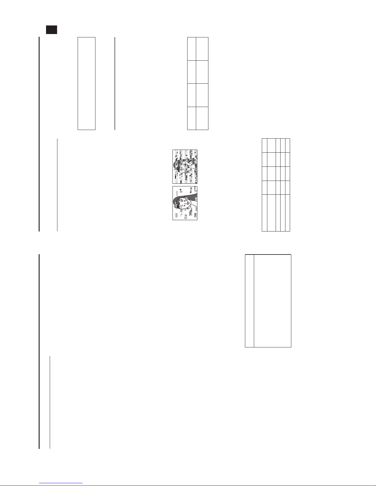
headcleaning is not performed periodically, a type of
mosaic noise called block noise may appear in the picture
or sound may be interrupted.
•Please use cleaning tape produced by JVC. Do not use
head cleaning tapes other than specified.
XSee “Precautions for Use of Head Cleaning Tape”
about how to use the head cleaning tape and precautions
for use of the head cleaning tape.
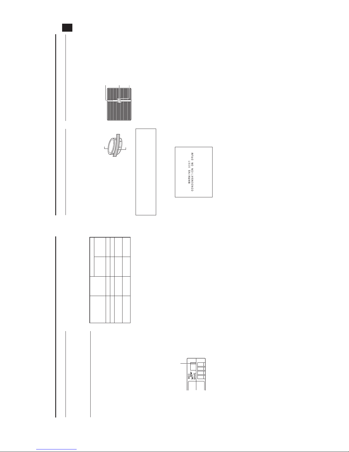
•When dust adheres to the heads, the warning message
“HEAD CLEANING REQUIRED!” is displayed on the LC
monitor and in the viewfinder during playback, edit search,
and recording check using the RET button on the lens sec-
tion.
Periodical Maintenance
Contents : Check or replace the following mechanical parts
according to the running time.
G: Clean, check and adjust.
E: Clean and check. Replace as required.
F: Replace.
•Themaintenance contents vary depending on the operat-
ing environment and method. Therefore, the above data
should be considered as a reference.
Time management
The accumulated running time of the unit can be confirmed
with the hour meter display (which shows the accumulated
drum and fan motor running time). XSee “How to Display
the Hour Meter” on page 89.
Precautions for Use of Head
Cleaning Tape
Please use cleaning tape produced by JVC.
Adhere to the following precautions when using the head
cleaning tape.
1. Insert the cleaning tape.
Press the PLAY/STILL button after the cleaning tape is
fully loaded.
The tape runs for 10 seconds at a time in the PLAY mode.
(The tape stops automatically and then the unit enters the
STOP mode.)
2. Do not use the tape more than four times at the most for
each cleaning.
Use the following chart as a guide for periodical head
cleaning.
Note 1) When used in a low humidity environment, head
cleaning should be conducted at intervals half of
those given in the below chart.
Note 2) If an M-DV80 tape is used immediately after head
cleaning, the “HEAD CLEANING REQUIRED!”
indicator may remain on. In this case, let the tape
run as the indicator will turn off after the tape has
run for a while.
Note 3) Use the cleaning tape in the room temperature
(10°C to 35°C).
Note 4) The cleaning tape case contains instructions for
use of the cleaning tape. However, some of these
instructions differ from the contents of this sheet.
When using the cleaning tape, please follow the
instructions of this sheet.
Note 5) If the “HEAD CLEANING REQUIRED!” does not
disappear after repeated head cleanings, the
recording tape may be abnormal. Avoid excessive
repeated use of the head cleaning tape.
Usage Time 500H 1000H 1500H 2000H
Drum assembly (includ-
ing heads) GEEF
Tape guides, rollers GEEF
Belt gears HE EF
Drive parts HHE F
Block Noise
For consultations related to the maintenance planning or
cost, please contact the person in charge of professional
video equipment at your nearest JVC-authorized service
agent.
Running
Low
temperature
Room
temperature
High
temperature
Operating envi-
ronment
0°C to 10°C 10°C to 35°C 35°C to 40°C
Yardstick for
use of cleaning
tape
1 to 2 times ev-
ery 5 hours
1 to 2 times ev-
ery 20 to 30
hours
1 to 2 times ev-
ery 5 hours
8
INTRODUCTION
Battery Pack to be Used
The GY-HD100 can use any of the following batteries.
•BN-V428, BN-V438
Videocassette to be Used
•UseJVC’s videocassette tapes marked with the Asym-
bol.
•Mini DV videocassette : M-DV63HD
M-DV63PROHD
* Do not use M-DV80.
•Videocassettes cannot be used upside down.
•Avoid storing a videocassette with its tape not being com-
pletely wound, as this may damage the tape. Rewind it to
the beginning before placing a cassette into storage.
•Storevideocassettes in a place with little humidity and
good ventilation where mould does not form.
•After a videocassette tape has been used repeatedly, it
becomes unable to maintain full performance due to an
increase in noise caused by dropouts, etc. Do not continue
to use a dirty or damaged tape, as this will reduce the
rotary head life.
•Videocassette tapes with the Asymbol are provided
with a switch on the back to prevent accidental erasure.
•Slide the switch to SAVE to protect the required recording
in the tape from being overwritten.
•Torecord on the tape, slide the switch to REC.
For recording and storing videotapes in
the best condition
Observe the following instructions for the best recording and
storage of videotapes.
•Takecare of the conditions of handling videotapes. It is rec-
ommended that you record and store videotapes in the
environment below.
•Donot leave the videotapes neglected for a long period. If
videotapes are left wound for a long period of time, it may
result in distortion of the tape. Also it may cause tape-to-
tape adhesion (known as blocking). It is recommended that
videotapes be unspooled and rewound once a year for
refreshing.
•When tapes are not in use, store them in cases and on
end. Storage cases protect videotapes from humidity, dust
and ultraviolet light. Keep tapes in cases and do not store
them lying flat. When housed in a horizontal position, pres-
sure from other tapes can cause distortions and deforma-
tions of the tape edges.
Switch
Recording
Storage
Short period
(Up to 10
years)
Long period
(Over 10
years)
Temperature 17°C to 25°C 15°C to 23°C 15°C to 19°C
Humidity 30% to 70% 40% to 55% 25% to 35%
Hourly temperature
change
Less than
10°C HH
Hourly humidity
change
Less than
10% HH
9
INTRODUCTION
Condensation
•Ifthe unit has been cooled down in a cold place and is then
carried to a warm place, the moisture contained in the
warm air may adhere to the head drum or tape guides and
be cooled into water droplets. This phenomenon is referred
to as condensation (dewing). When this occurs, the head
drum and tape guides are covered with droplets allowing
the tape to be stuck to them, leading to tape damage.
•Condensation occurs in the following cases:
•When the unit is suddenly moved
from a cold place to a warm place.
•When a room heater has just
started or when the unit is exposed
directly to cold air from an air con-
ditioner.
•When the unit is placed in a very
humid place.
•“CONDENSATION ON DRUM” is displayed on the LCD
monitor and in the viewfinder when condensation occurs in
this unit.
Keep the power on until the warning message disappears.
•Payattention to condensation even before the condensa-
tion indication appears.
As condensation forms gradually, the condensation indica-
tion may not appear for the first 10-15 minutes after con-
densation has formed inside.
In an extremely cold place, the condensation could freeze
and turn into frost. In such a case, it takes an additional 2-3
hours for the frost to first melt into condensation and then
to be dissolved.
•Toprevent condensation
When moving the unit from one place to another where the
temperatures are greatly deferent, first remove the video-
cassette, place the unit in a tightly sealed vinyl bag, and
then move it to a new environment.
To ensure no condensation occurs, allow the temperature
of the unit in the bag to reach that of the new environment
before using it.
Characteristic CCD Phenomena
Smear and Blooming
Due to the physical structure of a CCD it is possible to induce
vertical streaking (called “smear”) when shooting an
extremely bright light source. Another effect is the expansion
of light around a bright light or object (called “blooming”).
The CCD employed in this unit is characterized by inducing
very little smear or blooming. Nevertheless, please take note
that smear or blooming may be induced when shooting a
bright light source.
Moire or Aliasing
Shooting stripes or fine patterns may cause a jagged effect or
a banding in fine mesh patterns.
White dots
High temperatures can cause CCD sensor pixels to produce
the effect of white dots in the image. This condition is conspic-
uous especially when gain is applied.
This is a characteristic of the charged-coupled device (CCD).
As far as possible, use the unit under conditions where the
temperature of the unit does not increase.
Do not leave the videocassette inserted when moving the
camera under conditions where the temperature environ-
ment changes.
After moving the unit, do not use until the internal parts have
stabilized.
Head drum
Video tape
Smear
Vertical pale streaking appearing at high
luminous object
High luminous object
(Electric light, sunlight, etc.)
Blooming
Blurring in highlight
Monitor screen
10
CONTROLS, INDICATORS AND CONNECTORS
ZOOM Lens (Optional)
Th16 x 5.5BRMU
1FOCUS ring
Manual focus ring.
2ZOOM lever/ring
This is the manual zoom ring equipped with a zoom lever.
To adjus t t he zoom manually, turn the zoom mode knob b
to position “M”.
3IRIS ring
Manual iris ring. To activate the auto iris feature, set the Iris
Mode switch 7to “A”.
4[VTR] VTR trigger button
To start/stop shooting.
5[RET] Return video button
You can only monitor the return video signal from the VTR
from the viewfinder, LCD monitor and video signal connec-
tor while this button is pressed.
When you set the LENS RET item to “FOCUS ASSIST” in
the SWITCH MODE menu screen, you can use this button
as the FOCUS ASSIST button.
XSee page69.
6ZOOM servo control lever
To operate the servo zoom feature with this lever, set the
ZOOM knob bto “S”.
•Pressing the “W” section of this lever increases the
angle of the lens for a wider shooting angle.
•Pressing the “T” section of this lever narrows the lens
angle perspective for telephoto shots.
•Pushing harder changes the speed of the zoom.
7IRIS mode switch
8Momentary auto iris button
When the IRIS mode switch 7is at “M”, pushing this but-
ton activates the Auto Iris Function while it is held down
only.
9[S] IRIS speed adjusting control
For adjusting the iris operation speed.
MEMO
If the speed becomes too fast, hunting may occur. To avoid
the phenomena described above, perform adjustment
again.
0FILTER thread
Protect the lens with a clear filter or UV filter by screwing
the filter onto the thread inside the lens hood from the front.
Other filters can be used for various effects.
aZOOM servo connector
Connect an optional zoom servo unit here.
b[ZOOM] ZOOM mode knob
cBACK FOCUS ring/fixing screw
For back focus adjustment only. Secure with the screw
knob after adjustment. XSee “Back Focus Adjustment”
on page 42.
dMacro focusing ring (for close-up shooting)
By rotating this ring in the direction of the arrow, close-up
shooting of very small objects becomes possible.
Normal focus adjustment and zooming are not available in
the macro mode.
To shoot images in the macro mode, set the focus ring 1
to the infinite position (f) and the zoom ring 2to the max-
imum wide-angle position. To adjust the focus of the macro
image, rotate this ring in the direction of the arrow until the
object is focused.
CAUTION
•The back-focus knob is located close to the macro ring,
be careful not to mistake the back-focus knob for the
macro ring.
•After the required operation, be sure to return the macro
focusing ring to the normal position.
XSee “Attaching the Zoom Lens (Provided)” on page 29.
XSee “Back Focus Adjustment” on page 42.
M
RET
WT
A
MACRO
32
456789
1
0
abc
d
A:Activates the auto iris feature.
M:Allows manual iris control.
S:Servo zoom mode. Allows operation by the zoom
servo control lever 6.
M:Manual zoom mode. Allows zoom control by the
zoom lever/ring 2.
11
CONTROLS, INDICATORS AND CONNECTORS
Front Section
1Shoe
Makes it possible to mount separately sold lights and
accessories.
2Knob
This is the mounting knob for the microphone holder 3.
3Microphone holder
Makes it possible to attach the provided microphone or a
separately sold microphone.
XSee “Attaching the Microphone (Provided)” on page 29.
4Front tally lamp
This lamp lights up when the GY-HD100 enters the record
mode. It blinks during the transition to the record mode.
When the tape has run out, or the VTR enters the warning
mode, it blinks quickly.
•UsetheFRONT TALLY item on the OTHERS [1/2] menu
screen to select whether or not the lamp should light and
the lighting pattern.
XSee page 77.
5[LENS] Lens control connector
Connect 12-pin lens control cable from lens here.
6[ZEBRA] Zebra switch
When this switch is ON, a zebra pattern is imposed on the
viewfinder or LCD areas having luminance levels in accor-
dance with the menu settings made for the video signal.
This pattern can be used as a reference for manual adjust-
ment of the lens iris. Zebra patterns are also displayed dur-
ing color bar display when this switch is set to ON.
•The default value is 70% - 80%. The luminance level can
be changed with the ZEBRA setting in the LCD/VF [1/3]
menu screen.
XSee page71.
While this switch is pressed to the SKIN AREA side, the
color tone areas specified with the SKIN COLOR ADJUST
item on the ADVANCED PROCESS menu are indicated in
the viewfinder. The switch returns to the OFF position
when released.
XSee “How to Use Skin Detail” on page 82.
*The Skin Detail color tone areas are not indicated while
the color bar or VTR playback picture is shown in the
viewfinder or on the LCD monitor.
7[AWB] Auto white balance button
When the WHT.BAL switch con page 15 is set to A or B
and you press this button, the white balance is automati-
cally adjusted.
*It is not activated in preset, full auto shooting, full auto
white balance and color bar modes.
XSee “White Balance Adjustment” on page 43.
8Lens mounting ring/Lens lock lever
Hold the lens and use the lever to turn the ring anticlock-
wise to release lens.
To mount lens make sure the lens guide pin fits well, and
then turn the ring clockwise until firm.
XSee “Attaching the Zoom Lens (Provided)” on page 29.
Pin
No. Function Pin
No. Function
1Return switch 7 Iris position
2VTRtrigger 8IRIS A/R INPUT
3GND 9EXTENDER position
4
Lens AUTO/MANU control
10 ZOOM position
5IRIScontrol 11 –
6+12V DC 12 –
32 1
4
5
8
7
6
12
CONTROLS, INDICATORS AND CONNECTORS
Rear Section
1Back tally lamp
This lamp lights up when the GY-HD100 enters the record
mode. It blinks during the transition to the record mode.
When the tape has run out, or the VTR enters the warning
mode, it blinks quickly.
•UsetheBACK TALLY item on the OTHERS [1/2] menu
screen to select whether or not the lamp should light and
the lighting pattern.
XSee page 77.
2[PHONES] Earphone jack
This is a stereo mini-jack for connecting an earphone for
audio monitoring. Plug in an earphone or headphone with a
3.5 mm diameter plug. The earphone can also be used to
monitor alarm tones in accordance with the circumstances.
The audio channel to be output is selected with the AUDIO
MONITOR item on the AUDIO/MIC menu screen and
MONITOR SELECT switch eon page 18.
The audio output level is adjusted with the Audio monitor
volume control 3on page 14.
MEMO
•Thevolume of the alarm sound is set with the ALARM VR
LEVEL item on the OTHERS [1/2] menu screen.
•When using a stereotype jack and stereo sound should
be output, the following setting should be performed.
Set the MONITOR SELECT switch eon page 18 to
BOTH.
Set the AUDIO MONITOR item on the AUDIO/MIC menu
screen to STEREO.
3Shoulder belt hooks
Allows you to attach a separately sold shoulder belt.
4LCD monitor
Shows a color camera image or the VTR playback picture.
It is also used for displaying the following:
•Menu Setting screens
•Characters showing the whether the GY-HD100 is set to
shooting mode or VTR playback mode
•Date and time and time code
•Audio level meter
•Warningindications, etc.
XSee page 19.
5Tripod mount
Use this hole when mounting the camera onto a tripod.
(Use a screw shorter than 8 mm.)
Always make sure that the camera is securely mounted.
6Rotation-preventive hole
Use this to prevent the camera from falling off the tripod.
Always make sure that the camera is securely mounted.
1
2
3
4
5
6
13
CONTROLS, INDICATORS AND CONNECTORS
LCD Door
1[LCD BRIGHT +/–] LCD brightness +/– button
This button is for adjusting the brightness of the LCD moni-
tor display.
•Pushing the button in the + direction makes the monitor
brighter.
•Pushing the button in the – direction makes the monitor
darker.
•Pushing the +/– buttons simultaneously returns the set-
ting to the standard setting.
2[CH-1/CH-2 AUDIO SELECT] CH-1/CH-2 audio selector
switch
Selects the method of adjusting the CH-1 and CH-2 audio
channel audio levels.
3[TC DISPLAY] TC/UB display switch
Selects the contents displayed on the TC counter of the
LCD monitor or in the viewfinder. (This switch works when
the TC/UB item on the LCD/VF [2/3] menu screen is set to
ON.)
4[TC GENE.] Time code generator setting switch
Switch for setting the time code generator to preset mode
or regeneration mode. It is also used to select the time
code run mode when the preset mode is selected.
MEMO
Preset of time code and user’s bits is performed on the TC/
UB/CLOCK menu.
XSee page 39.
XSee “TC/UB/CLOCK Menu Screen” on page 74.
5[CAM/VTR] Camera/VTR mode switch button
Each time you press this button, the mode switches
between camera mode and VTR mode.
When you do this, the VTR indicator gon page 18 dis-
plays the following statuses.
While the mode is being switched : Flashing
In VTR mode : Lit
In camera mode : Off
•Select the Camera mode to record the camera image.
•Selectthe VTR mode to playback VTR or to input the
HDV/DV signal from the IEEE1394 connector 4on
page 16. (HDV/DV signal input is possible with the GY-
HD100U/GY-HD101E.)
•Whenthe power is turned on, the mode becomes the
Camera mode.
AUTO : A limiter works to suppress the audio level
when excessive audio is input.
When the input level is low, the audio level
does not increase.
The “AUTO” LED in the CH-1/CH-2 AUDIO
LEVEL area gon page 15 lights.
MANUAL : Allows you to adjust the audio levels using the
CH-1/CH-2 AUDIO LEVEL volume controls g
on page 15.
When “ON” is set for the FULL AUTO switch
hon page 18, this becomes “AUTO” mode.
TC : Set to this position to display time code values.
UB : Set to this position to display the user’s bits values.
5
1
2
34
FREE : The preset mode is selected, and the time
code run mode becomes the FREE run mode.
Set to this position to record with the time
code or user’s bits set anew (preset). In this
setting, the time code always operates in the
run mode.
*Ifthis setting is used when recording
scenes one after another, the time codes
become discontinuous at the transition
points between scenes.
REC : The preset mode is selected, and the time
code run mode becomes the REC run mode.
Set to this position to record with the time
code or user’s bits set anew (preset). The
time code operates in the run mode during
recording only. If this setting is used when
recording scenes one after another, the time
codes are recorded as continuous time codes.
REGEN : Regeneration mode, in which the unit reads
existing time codes on the tape and records
time codes in continuation of the existing
ones. Set to this position when you want to
add additional time codes to time codes
already recorded on the tape.
14
CONTROLS, INDICATORS AND CONNECTORS
Right Side Section
1Monitoring speaker (Ear pad)
•In the Camera mode, the input sound can be EE moni-
tored.
In the VTR mode, the speaker outputs the VTR playback
sound.
The sound to be output is selected with the MONITOR
SELECT switch eon page 18.
•The sound level is adjusted with the MONITOR sound
level volume 3. This speaker also outputs various
warning sounds superimposed on other sound.
XSee “Alarm Sound” on page 87.
2Ear pad set screw
Screw for adjusting the height of the ear pad.
3[MONITOR] Audio monitor volume control
Adjusts the volume of the monitoring loudspeaker and ear-
phone.
4[VF BRIGHT] Viewfinder brightness adjustment
To adjust the brightness of the viewfinder.
XSee page 41.
5[PEAKING] Contour adjustment
To adjust the contours of the LCD monitor and viewfinder
image.
*When the Focus Assist function is running, this control
does not operate.
XSee page 41.
6[FOCUS ASSIST] Focus assist button
When you press this button during shooting, the area of
focus is displayed in blue, red or green, making it easy to
focus accurately.
XSee “LCD/VF [1/3] Menu Screen” on page 71.
7Clamp
Attach the cable from the viewfinder here.
8[USER1/2/3] User buttons
You can assign camera functions to the USER1 - 3 but-
tons.
Use them to switch shooting conditions depending upon
the subject.
Set them using the USER1 - 3 items in the SWITCH MODE
menu screen.
XSee page 69.
MEMO
•TheUSER buttons work together with the menu settings.
•When a menu screen is being displayed, they also func-
tion as menu operation buttons. XSee “Setting Menu
Screens” on page 60.
9[SHUTTER] Shutter/Menu dial
•Every time this dial is pressed while in the normal screen
mode (when the menu screen is not displayed), the
shutter speed switches between on/off.
•Whenthisdial is turned 1 click up or down in the normal
screen mode, the shutter speed indicator is shown for
about 3 seconds on the LCD monitor or in the viewfinder.
The shutter speed is changed when this dial is turned
while the shutter speed indicator is shown.
XSee page 69.
•Whenthisdial turned upward or downward while the
menu screen is displayed, the cursor (K) also moves
upward or downward to allow selection of items in the
menu. To change the setting value of the item, press this
dial. When the setting value starts blinking, turn this dial
upward or downward to change the setting.
XSee “Setting Menu Screens” on page 60.
0[ND FILTER] ND filter switch
Switches the built-in ND filter.
When you change this switch, the type of the new ND filter
is displayed in the LCD monitor or viewfinder.
CAUTION
If you switch the ND filter while shooting is in progress, the
picture may be disturbed or noise may occur in the audio.
XSee “Camera Settings” on page 45.
a[STATUS] Status/Menu button
•Pressing this button in the normal screen mode (condi-
tion in which the menu screen is not shown) displays a
status screen in the viewfinder or on the LCD monitor.
The displayed status screen changes each time the but-
ton is pressed.
XSee “Status Screens” on page 19.
•Pressing this button for more than 1 second in the nor-
mal screen mode displays the menu screen in the view-
finder or on the LCD monitor. Pressing this button while
the menu screen is displayed in the viewfinder or on the
LCD monitor makes the menu screen disappear.
XSee “Setting Menu Screens” on page 60.
USER 3USER 2USER 1
STATUS
MENU
2
1
ND FILTER
REC
OFF
ON
POWER
VF BRIGHT
WHT.BAL
AUTO
AUDIO
LEVEL
AUTO
CH-1 CH-2
1
2
3
4
5
6
7
8
9
0
a
b
c
defgh
ji
OFF : Turns the filter OFF (FILTER OFF)
1:
Cuts the light intensity to approximately 1/4. (1/4ND)
2:
Cuts the light intensity to approximately 1/16. (1/16ND)
15
CONTROLS, INDICATORS AND CONNECTORS
b[GAIN] Sensitivity selector switch
Electronically boosts the light sensitivity when there is
insufficient illumination on the subject.
The boosting level differs depending on the switch position
as follows:
(Factory presets)
L:0dB(no boosting is applied)
M:9dB (boosted to approximately 3 times the original)
H:18 dB (boosted to approximately 8 times the original)
•The boosting level for each switch position can be
changed with the SWITCH MODE menu screen.
XSee page 69.
The more the boosting level is increased, the more the
resulting image will be noisy.
•When the FULL AUTO switch hon page 18 is “ON”,
this is fixed at “ALC”.
c[WHT.BAL] White balance switch
Three white balance modes are selectable with this switch.
FAW (Full Auto White Balance) mode can be set to A, B or
PRESET with the SWITCH MODE menu screen.
XSee page 69.
In the FAW mode, video color temperatures are constantly
sampled for automatic adjustment to a proper white bal-
ance.
•When the FULL AUTO switch hon page 18 is “ON”,
this is fixed at “FAW”.
dStand
When attaching the lens, slide the stand forward.
CAUTION
There is a risk that the camcorder will fall onto the viewfinder
side when the lens is not attached, so leave the lens
attached even if you are not using it.
e[POWER] Power ON/OFF switch
Switch that turns the power ON/OFF.
When the power is OFF, “POFF” is displayed in the LCD
monitor or viewfinder.
*Waitatleast 5 seconds if you need to turn the power on
again.
f[REC] REC trigger button (start/stop recording)
Start and stop recording using this button.
(This works together with the REC trigger button on the top
and the lens VTR trigger button.)
When “SPLIT” is set for the 1394 REC TRIGGER item on
the OTHERS [2/2] menu screen, this button becomes the
start/stop recording button for an external device.
XSee page 78.
XSee “Backup Recording” on page 58.
g[CH-1/CH-2 AUDIO LEVEL] CH-1/CH-2 Audio level con-
trols and AUTO LED
Allow you to adjust the audio level for the CH-1 and CH-2
audio channels.
•Touse these controls, set the CH-1/CH-2 AUDIO
SELECT switch 2on page 13 to “MANUAL”.
•When the FULL AUTO switch hon page 18 or the CH-
1/CH-2 AUDIO SELECT switch 2on page 13 is set to
“AUTO”, “AUTO LED” lights. (The audio level controls do
not work.)
h[HDV/DV LED]
•In camera mode, this lights according to the setting for
the video format being shot.
•InVTRmode, it lights according to the video format
being recorded on tape or the IEEE1394 input video for-
mat.
MEMO
•During a system error, HDV/DV flash alternately.
XSee page86.
•Selectwhether or not to have this light in the FORMAT
LED item on the OTHERS [1/2] menu screen.
XSee page77.
iLCD door lock and release knob
To open the LCD door, move this knob on the direction
toward the rear section.
jLCD door
LCD monitor door.
The LCD monitor is located on the inner side of the door.
The LCD monitor can be viewed when this door is opened.
The door can be turned to change the orientation of the
LCD monitor, and it can be rotated so that it can be accom-
modated in the main body of the camera.
XSee page 41.
B:Switch into white balance mode memorized in
B. If white balance is performed with the
switch in this position, it will be memorized
into B.
A:Switch into white balance mode memorized in
A. If white balance is performed with the
switch in this position, it will be memorized
into A.
PRST
(PRESET)
:Switch into white balance mode (3200K or
5600K) set in PRESET TEMP. item on the
CAMERA OPERATION menu screen.
XSee page 64.
HDV : Lights when the format is HDV.
DV : Lights when the format is DV.
16
CONTROLS, INDICATORS AND CONNECTORS
Left Side Section
1[DC INPUT] DC connector
Power input for 7.2 V DC accepts the supplied AC adapter.
XSee “AC Operation” on page 31.
2[LINE OUTPUT] Line output connector ()3.5mm)
Output connector for audio signals.
•Outputs the input audio signal in the Camera mode.
•Outputsthe playback audio signal in the VTR mode.
•When a HDV/DV signal (IEEE1394) is input, the EE
sound of the input audio signal is output in the VTR
mode. (GY-HD100U/GY-HD101E only)
MEMO
Alarm sound is not output.
3[IEEE1394] IEEE1394 switch
Input/output signal and playback signal video from the
IEEE1394 connector 4. Set this switch according to the
format.
4[IEEE1394] IEEE1394 connector (6-pin)
Using an IEEE1394 cable (optional), a digital video compo-
nent with IEEE1394 connector can be connected here.
XSee“Connecting the IEEE1394 Cable” on page 54.
XSee “HDV/DV Dubbing” on page 56.
5[VIDEO/Y, PB, PR] Video Signal Output Connectors
(RCA)
These are connectors for component or composite video
signal output.
The signal switches automatically depending upon the
cables connected to these connectors.
•Youcan select the output signal using the OUTPUT
TERMINAL item on the VIDEO FORMAT menu.
You can also select whether or not to add a setup signal
in the SET UP item. XSee page63.
•When the OUTPUT CHAR. item on the OTHERS [1/2]
menu screen is ON, the menu setting screen is also dis-
played in the video from the video signal output connec-
tor. XSee page 77.
XSee “Dubbing with AV Devices” on page 55.
MEMO
Put the covers on the connectors when you are not using
them.
6Cassette cover
Sliding the EJECT switch aon page 17 located on the top
section opens this cover to allow insertion or removal of the
videocassette.
CAUTION
To prevent foreign objects from entering the internal parts of
the VTR unit, do not leave the unit with the cover open for
extended periods of time.
7Viewfinder connector (6-pin)
Connect the cable from the viewfinder here.
8[CH-2 INPUT] CH-2 audio input connector selector
switch
Selects the CH-2 audio input connector.
MEMO
The audio from the INPUT1 connector is also input into
CH-1 regardless of the setting.
9[AUDIO INPUT] Audio input signal selector switch
This switch is used to select the input sound signal from
INPUT1 or INPUT2 connector.
CAUTION
When connecting a component that does not require +48 V
power supply, make sure that the switch is not set to
MIC+48V before the component is connected.
MEMO
You can select the normal input level for MIC and MIC+48V
in the INPUT1, 2 MIC REF. item on the AUDIO/MIC menu
screen.
XSee page70.
0[INPUT1/INPUT2] INPUT1/INPUT2 audio input connec-
tors
These are audio input connectors for connecting to an
external audio device or microphone.
•Setthe [AUDIO INPUT] switch 9according to the
device to be connected.
•SettheCH-2 audio input connector using the [CH-2
INPUT] switch 8.
The CH-2 audio from the set connector is recorded.
aShoulder pad slide button
Button to adjust the position of the shoulder pad.
When you press this button, you can move the position of
the shoulder pad bforward or backward.
bShoulder pad
HDV : For HDV format
DV : DV format
1
2345 6
7
8
9
0ab INPUT1 : Inputs the audio from the INPUT1 connector
0into CH-2.
INPUT2 : Inputs the audio from the INPUT2 connector
0into CH-2.
LINE : Set to this position when connected to audio
equipment, etc. The reference input level is
+4 dBs.
MIC : Set to this position when the dynamic micro-
phone is connected.
MIC+48V : Set to this position when a microphone requir-
ing +48 V power supply (phantom micro-
phone, etc.) is connected.
17
CONTROLS, INDICATORS AND CONNECTORS
Top Section
1Viewfinder
Displays the camera image and the playback picture.
2Eyepiece
Ensures that ambient light does not reach the viewfinder
screen or falls into the eye of the cameraman.
3Eyepiece focus ring
You can adjust the focus by turning this ring.
4Eyepiece mounting ring
You can adjust the position of the eyepiece forward or
backward by loosening this ring.
5Slide mounting ring
You can adjust the position of the viewfinder left or right by
loosening this ring.
6Clamp
Attach the microphone cable here.
7[FOCUS ASSIST] Focus assist button
When you press this button during shooting, the area of
focus is displayed in blue, red or green, making it easy to
focus accurately.
XSee “LCD/VF [1/3] Menu Screen” on page 71.
8[REC] REC trigger button (start/stop recording)
Start and stop recording using this button.
(This works together with the REC trigger button on the
right panel and the lens VTR trigger button.)
9[REC LOCK] REC LOCK switch
Slide this switch in the direction of the arrow to lock the
[REC] trigger button 8. Use this to prevent unwanted
recording.
(The REC trigger button on the right panel and the lens
VTR trigger button are not locked.)
0SD memory card cover
When you open this cover, you can insert and remove the
SD memory card.
XSee “Inserting an SD Memory Card” on page 30.
When an SD memory card is loaded
•You can save, call up and reset the menu settings on
this camcorder.
•Youcaninitialize (format) an SD memory card.
XSee “FILE MANAGE Menu Screen” on page 79.
a[EJECT] Eject switch and LED
Slide this switch to the side to insert or eject a videocas-
sette tape.
The LED lights while ejecting is in progress.
MEMO
•It takes a few seconds before the videocassette is
ejected. Do not close the cassette cover during the eject
operation.
•Donottouch the cassette insertion slot or cassette during
the eject operation. This could result in damage.
bOperation cover
Open this cover when operating in the playback mode.
Otherwise, keep this cover closed.
This cover can be opened by sliding it to the side.
MEMO
When the STOP button iis pressed in the Camera mode
to set the VTR operation mode indicator to indicate STOP,
playback operations become possible.
c[BATTERY RELEASE] Battery pack lock release lever
Slide this lever forward to remove the battery pack.
dBattery pack
Attach the provided battery pack (BN-V428).
XSee “Battery Operation” on page 32.
1
2
3
4
56
7
8
9
0
a
b
c
d
e
f
g
h
i
j
k
l
18
CONTROLS, INDICATORS AND CONNECTORS
Top Section (Cont’d)
e[MONITOR SELECT] Audio monitor selector switch
This switch is used to select the monitor sound output and
playback sound output from the monitoring speaker 1on
page 14 or the PHONES jack 2on page 12.
XSee “Outputting Audio” on page 53.
XSee “AUDIO/MIC Menu Screen” on page 70.
CAUTION
Make sure to move switches all the way. Do not leave a
switch stopped in a midway position. Noise will be gener-
ated and operation irregularities will occur.
f[DISPLAY] Display button
Each time you keep pressing the DISPLAY button about 2
seconds, switch LCD monitor display and viewfinder dis-
play.
g[VTR] VTR indicator
This indicator lights when the camera is in the VTR mode.
To perf orm VTR playback or to input the HDV/DV signal
from the IEEE1394 connector 4on page 16, press the
CAM/VTR button 5on page13 to turn on this indicator.
It flashes when the mode is being changed.
(DV signal input is possible with the GY-HD100U, GY-
HD101E.)
h[FULL AUTO] Full auto shooting (FAS) switch
This is the ON/OFF switch for FAS mode.
•During FAS mode, “FAS” is displayed on the LCD moni-
tor or the viewfinder.
•FAS mode works together with the auto iris and auto
level control (ALC) modes and automatically adjusts to
the optimal video signal level and white balance.
•The audio recording level sets to automatic adjustment
mode.
•Evenifthere are color bars, this automatically sets to
camera video.
•SMOOTH TRANS mode does not run. XSee page 64.
•Auto iris mode operates even if the lens iris mode switch
is set to the manual position.
•The gain changes continuously until it reaches the maxi-
mum ALC MAX setting, and the shutter speed also
changes continuously.
•When you release FAS mode, all of the settings return to
their previous modes.
CAUTION
When the power is turned on while the camera is in the FAS
mode, it takes about 10 seconds before the automatic
adjustment of FAS is completed.
All of the previous setting contents are recalled when the
FAS mode is cancelled.
i[STOP] Stop button
Press to enter the stop mode.
j[REW] Rewind button
Press this button to rewind the tape.
•Pressing this button in the stop or fast forward mode ini-
tiates the rewind mode. (Only for VTR mode)
•Pressing this button during playback, still picture play-
back or forward search initiates reverse search.
k[PLAY/STILL] Play/still button
Press to start playback. Press to enter the still picture
mode during playback, in the stop mode or in the search
mode.
Depending on the ambient temperature, if still image play-
back mode continues for between 30 seconds and 3 min-
utes, it stops automatically. (Tape protect mode)
During still picture playback and search mode, press this
button to return to the normal playback mode.
*If the auto tracking is active at the moment the play
mode is entered, the playback video will be interfered
with digital noise.
l[FF] Fast forward button
Press this button to fast forward the tape.
•Pressing this button in the stop or rewind mode initiates
the fast forward mode. (Only for VTR mode)
•Pressing this button during playback, still picture play-
back or reverse search initiates forward search.
CH-1 : The CH-1 channel audio is output.
BOTH : CH-1 and CH-2 channel audio are output mixed.
When this setting is selected, the menu screen
can be used to select whether the mixed sound or
stereo sound should be output via the PHONES
jack. (AUDIO MONITOR item on the AUDIO/MIC
menu screen)
When AUDIO MONITOR item on the AUDIO/MIC
menu screen is set to “STEREO”, only the audio
of CH-1 is output from the monitoring speaker.
CH-2 : The CH-2 channel audio is output.
19
CONTROLS, INDICATORS AND CONNECTORS
Indications on the LCD Monitor and in the Viewfinder
•CAMERA MODE (display example)
In addition to showing the EE image and the playback picture,
the LCD monitor and viewfinder are also used for the follow-
ing character displays.
To sh o w characters on the LCD monitor, press the DISPLAY
button briefly.
Status screens (screens for checking the current cam-
era settings)
Auto white display (only displayed in the Camera
mode)
Menu setting screens
Alarm message display
Safety zone display (only displayed in the Camera
mode)
MEMO
When the OUTPUT CHAR. item on the OTHERS [1/2] menu
screen is ON, the menu setting screen is also displayed in
the video from the video signal output connector.
Status Screens
Press the STATUS button while normal screen is displayed to
show one of the status screens.
The contents of the status display are divided into those for
the Camera mode and those for the VTR mode.
•Eachtimethe STATUS button is pressed in the Camera
mode, one of 5 status screens is displayed. (STATUS 0, 1,
2, 3, 4)
•One type of screen is displayed in the VTR mode.
MEMO
•When the STATUS button is pressed for 1 second or
longer, the menu setting screen is displayed.
To display the Status screen while the menu setting
screen is displayed, press the STATUS button to return to
the normal screen.
•Youcanswitch between the LCD monitor and the view-
finder by holding down the DISPLAY button for about 2
seconds.
USER 3USER 2USER 1
STATUS
MENU
SHUTTER
2
1
OFF
ND FILTER
WHT.BAL
AUTO AUTO
DISPLAY button
STATUS button
STATUS 1STATUS 0
STATUS 2
STATUS 4
STATUSSTATUS 3
•VTRMODE
(display example)
20
CONTROLS, INDICATORS AND CONNECTORS
Indications on the LCD Monitor and in the Viewfinder (Cont’d)
Status Screens in the Camera Mode
•STATUS0
1Event Indication
When the Gain or Shutter Speed is changed manually, the setting condition is displayed for about 3 seconds at the time the
change is made.
*1 The range for the shutter speed differs depending on the video format setting. XSee page 69.
*2 Displayed if functions were assigned to the USER1 - 3 buttons. XSee page 69.
*3 Displayed when the [WHT.BAL] white balance selector switch con page 15 is set to PRST (PRESET).
*4 “ ** ” depends on the video format.
STATUS 0 Screen
1
23
9
8
7
6
5
4
Setting Status Contents of Indications
Gain value was changed GAIN 0 dB, 3 dB, 6 dB, 9 dB, 12 dB, 15 dB, 18 dB
Gain value reached the ALC GAIN ALC
FULL AUTO was turned ON/OFF FULL AUTO ON, FULL AUTO OFF
ZEBRA was turned ON/OFF ZEBRA ON, ZEBRA OFF
Shutter speed value was changed *1 SHUTTER 1/6, 1/6.25, 1/7.5, 1/12, 1/12.5, 1/15, 1/24, 1/25, 1/30, 1/48, 1/50, 1/60, 1/100, 1/120,
1/250, 1/500, 1/1000, 1/2000,1/4000, 1/10000
Variable shutter speed value was changed *1 V. SHUTTER 1/24.01 to 1/1998.0
Shutter was turned OFF SHUTTER OFF [1/**] *4
White balance value was changed (Example)
WHITE BAL A <3200K>
Numeric value: Any of 2300, 2500, 2800, 3000, 3200, 3400, 3700, 4300, 5200, 5600, 6500,
8000
FILTER value was changed FILTER OFF, FILTER ND 1 [1/4ND], FILTER ND 2 [1/16ND]
AE LEVEL value was changed *2 AE LEVEL –3, –2, –1, NORMAL, +1, +2, +3
BLACK gain value was changed *2 BLACK NORMAL
BLACK STRETCH 1, 2, 3
BLACK COMPRESS 1, 2, 3
PRESET TEMP. value was changed *2 *3 WHITE BAL PRST <3200K>, WHITE BAL PRST <5600K>
HEADER REC is running HEADER REC
FOCUS ASSIST was turned ON/OFF FOCUS ASSIST ON, FOCUS ASSIST OFF
Timecode was set to zero reset TC ZERO PRESET XSee page 40.
REC LOCK switch was turned ON/OFF REC SWITCH LOCKED, REC SWITCH UNLOCKED XSee page 17, 9REC LOCK switch.
A REC command was sent from the IEEE1394
connector
TRIGGER TO HDV, TRIGGER TO DV
Other Displays XSee “FILE MANAGE Menu Screen” on page 79-81.
XSee “Warnings and Responses” on page 85.
21
CONTROLS, INDICATORS AND CONNECTORS
No. Item Contents
2VTR mode indication STBY : In record standby mode (record-pause mode)
REC : During recording
PLAY : During playback
FF : During fast forward
REW : During rewind
STL : During still picture playback mode
FWD:During playback in forward direction (FWD1: About ×2 speed, FWD2: About ×5 speed, FWD3:
About ×10 speed)
REV : During playback in reverse direction (REV1: About ×2 speed, REV2: About ×5 speed, REV3:
About ×10 speed)
STOP : Stop mode (Tape protect mode)
EJECT : Cassette being ejected
- - - : No tape loaded
3Indication of date and time Indicates the date and time.
Whether or not the date and time should be displayed as well as the display style are set on the TIME/
DATE menu.
LCD BRIGHT indication When the brightness of the monitor screen is adjusted with the LCD BRIGHT button, the date and time
indications and the VTR mode indication 2are turned off and the LCD BRIGHT indicator is displayed.
(Example)
BRIGHT +5 • ••••+•••••O
Numeric value: Any of –5, –4, –3, –2, –1, 0, +1, +2, +3, +4, +5.
4Indication of Black operation B : Displayed when the black stretch or black compress settings are other than NORMAL.
5Indication of skin tone detail
color operation
SD : Indicated when skin tone detail is ON.
6Indication of Iris level opera-
tion
I : Displayed when the AE LEVEL setting is other than NORMAL
7Indication of FAW operation FAW : Indicated when Full Auto White Balance is ON.
8Gain operation indication * dB : Indicates gain value when gain is other modes than 0 dB and ALC.
9Indication of various function
operations
FOCUS:Displayed when the Focus Assist function is ON.
SKIN AREA : Blinks while the skin detail color area is displayed.
ALC : Displayed when ALC function alone is ON.
FAS:Displayed when the Full Auto Shooting function is ON.
S:Displayed when the SHUTTER function is ON.
22
CONTROLS, INDICATORS AND CONNECTORS
Indications on the LCD Monitor and in the Viewfinder (Cont’d)
•STATUS1
In addition to the information on the STATUS 0 screen, this screen displays the following items.
STATUS 1 Screen
12
3
4
568
9
0
7
No. Item Contents
1VIDEO FORMAT display Displays the currently selected video format.
Allows you to select the REC item on the VIDEO FORMAT menu screen. XSee page 62.
You can switch this display ON/OFF using the FORMAT item on the LCD/VF [2/3] menu screen.
XSee page 72.
2Time Code (TC)/User’s Bits
(UB) indication
Indicates the time code (h:m:s:frame) or user’s bits data.
Whether or not to display this item is set with the TC/UB item on the LCD/VF [2/3] menu screen.
XSee page 72.
Whether the time code or user’s bits should be shown is selected with the TC DISPLAY switch inside the
LCD door.
3Remaining tape indication Remaining tape indication (displayed in 1-minute steps)
This indicator blinks when remaining tape time is equivalent to less than 3 minutes.
Whether or not to display this item is set with the TAPE REMAIN item on the LCD/VF [2/3] menu screen.
XSee page 72.
*When inserting a brand-new tape, the remaining tape time is not indicated.
When the tape has been run, the indication will appear.
*The remaining tape indication is to be regarded only as a guide.
*When the unit is used at low temperatures, it may take a while before the indication of the remaining tape
time appears.
4Voltage indication (Example) 7.0V: Indicates remaining battery level in 0.1V steps.
(Example) Time code TC 00 : 00 : 00 : 00
User’s bits UB FF EE DD 20
Colon (:) when non-drop frame mode
Dot (.) when drop frame mode
23
CONTROLS, INDICATORS AND CONNECTORS
5Audio sampling frequency in-
dication
32 K : Indicated when the AUDIO MODE item on the AUDIO/MIC menu screen is set to 32 K. (Audio is
recorded with 12-bit, 32 kHz sampling.)
48 K : Indicated when the AUDIO MODE item on the AUDIO/MIC menu screen is set to 48 K. (Audio is
recorded with 16-bit, 48 kHz sampling.)
XSee page 70.
6Audio level meter indication Displays the CH-1, CH-2 audio level meters.
Whether or not to display this item is set with the AUDIO item on the LCD/VF [2/3] menu.
XSee page 72.
7Standard audio level indication The level at which audio is recorded on the tape is indicated by “O”.
–20 dB, –12 dB
XSee “AUDIO REF.LEVEL” on page 70.
8Iris indicator display M:Iris set higher than normal
b:Iris set to normal
N:Iris set lower than normal
9Iris F-value indication Indicates the F-number of the connected lens.
OPEN, F2, F2.8, F4, F5.6, F8, F11, F16, CLOSE
It is not displayed when the lens is removed. For some lenses, no display appears.
The indication can be switched ON/OFF with the F.NO/IRIS IND. item on the LCD/VF [1/3] menu screen.
XSee page 71.
0Filter position indication Indicates the current filter position.
No display: FILTER OFF
ND1: FILTER ND1 (1/4ND)
ND2: FILTER ND2 (1/16ND)
The indication can be switched ON/OFF with the FILTER item on the LCD/VF [1/3] menu screen.
XSee page 71.
No. Item Contents
–20 dB –12 dB
OO
CH-1 OOOOO•••+
CH-2 OOOOO•••+
24
CONTROLS, INDICATORS AND CONNECTORS
Indications on the LCD Monitor and in the Viewfinder (Cont’d)
•STATUS2
This screen displays the camera setup statuses.
Event display is not available while this screen is displayed.
•STATUS3
Displays a list of setting statuses for USER1, 2, and 3 as well as LENS RET item on the SWITCH MODE menu screen.
XSee page69.
Events are not displayed while these statuses are being displayed.
•STATUS4
This screen only displays VTR mode indication, date and time, event display and alarm indications.
*Whether or not date and time should be displayed and the display style are set on the TIME/DATE menu screen.
XSee “Displaying the Time and Date on the Screen” on page 37.
STATUS 2 Screen STATUS 3 Screen
Indication Indication Contents
FILE FILE FCAM1 [********], CAM2 [********], and EXT1 - 4 [********] * indicates SUB NAME XSee page 79–81.
AFsymbol is displayed when a menu setting read from LOAD FILE was changed.
The display disappears when the setting is saved using STORE FILE.
FULL AUTO ON, OFF
GAIN 0dB, 3dB, 6dB, 9dB, 12dB, 15dB, 18dB, ALC
SHUTTER (When STEP is selected)
OFF, 1/6, 1/6.25, 1/7.5, 1/12, 1/12.5, 1/15, 1/24, 1/25, 1/30, 1/48, 1/50, 1/60, 1/100, 1/120, 1/250, 1/500, 1/1000, 1/2000,
1/4000, 1/10000
(When VARIABLE is selected)
1/24.01 - 1/1998.0
(Displayed when FAS or ALC mode is selected)
EEI
*The range for the shutter speed differs depending on the video format. XSee page 69.
WHITE BAL A<##00K>, B<##00K>, PRESET<##00K>, FAW
AE LEVEL –3, –2, –1, NORMAL, +1, +2, +3
FILTER OFF, ND1 (1/4ND), ND2 (1/16ND)
ZEBRA 60-70%, 70-80%, 85-95%, OVER 95%, OVER 100%
REMAIN Displays the remaining tape (minutes) and the type of tape (Ex: 60MIN (Y))
Y(Mini DV Videocassette)
AUDIO Displays the audio sampling frequency and the audio level adjustment mode (Ex: 32K (CH1 ZCH2 a)Z(for AUTO
mode) a(for MANUAL mode)
Indication Indication Contents
USER1
USER2
NONE, BARS, PRESET TEMP., B.STRETCH1, B.STRETCH2, B.STRETCH3, B.COMPRESS1, B.COMPRESS2,
B.COMPRESS3, AE LEVEL+, AE LEVEL–
USER3 NONE, BARS, PRESET TEMP., B.STRETCH1, B.STRETCH2, B.STRETCH3, B.COMPRESS1, B.COMPRESS2,
B.COMPRESS3
LENS RET RET, FOCUS ASSIST
25
CONTROLS, INDICATORS AND CONNECTORS
Status Screen in VTR MODE
12
3
9
4
5
6
78
0
No. Item Contents
1VIDEO FORMAT display Displays the video format recorded on the tape when in VTR mode.
You can switch this display ON/OFF using the VIDEO FORMAT item on the LCD/VF [2/3] menu screen.
XSee page 72.
MEMO
This camcorder cannot play back or output tape recorded in HDV 1080i format. “INVALID TAPE!” is dis-
played in the event display area 4.
2Time code (TC) and user’s bits
(UB) display
Displays the time code data being recorded (hour, minute, second, frame) when in VTR mode.
You can switch this display ON/OFF using the TC/UB item on the LCD/VF [2/3] menu screen.
XSee page 72.
You can select to display either the time code or the user’s bits using the TC DISPLAY switch in the LCD
door.
3Remaining tape time Remaining tape indication (displayed in 1-minute steps)
This indicator blinks when remaining tape time is equivalent to less than 3 minutes.
Whether or not to display this item is set with the TAPE REMAIN item on the LCD/VF [1/2] menu screen.
XSee page 72.
*When inserting a brand-new tape, the remaining tape time is not indicated.
When the tape has been run, the indication will appear.
*The remaining tape indication is to be used only as a guide.
*When the unit is used at low temperatures, it may take a while before the indication of the remaining tape
time appears.
4Event display Displays messages related to VTR operations. XSee page 85-86.
5Audio sampling frequency in-
dication
The audio sampling frequency used for the recording is displayed during playback.
(32 K, 48 K, 44.1 K)
6Audio level meter indication Displays the audio level meters during playback.
Whether or not to display this item is set with the AUDIO item on the LCD/VF [2/3] menu screen.
XSee page 72.
7VTR mode indication Indicates the VTR operation status
STBY, STOP, PLAY, REC, FF, REW, FWD, REV, STL, - - - (No tape loaded), SLOW: During variable play-
back in forward direction (Displayed when using non-linear editing software.)
(SLOW+1: About ×0.1 speed, SLOW+2: About ×0.2 speed, SLOW+3: About ×0.5 speed)
During variable playback in reverse direction (Displayed when using non-linear editing software.)
(SLOW–1: About ×–0.1 speed, SLOW–2: About ×–0.2 speed, SLOW–3: About ×–0.5 speed)
8Time/Date indication Recorded data are displayed during playback, fast forward, and rewind.
During recording, the data from the IEEE1394 connector is displayed.
(GY-HD100U/GY-HD101E only)
Whether or not the date and time should be displayed and the display style are set on the TIME/DATE
menu screen. XSee page 76.
When the date and time have not been set, the following indication appears.
- -/- -/- - - -: - -: - -
9Voltage indication (Example) 7.0V : Indicates remaining battery level in 0.1V steps.
0Audio Lock indication Displayed when the audio signal from DV recording or playback is locked to the video signal.
26
CONTROLS, INDICATORS AND CONNECTORS
Indications on the LCD Monitor and in the Viewfinder (Cont’d)
Auto White Balance Indication (Camera
mode only)
The AUTO WHITE indication and the result of the operation
are displayed during the auto white balance adjustment oper-
ation.
XSee “White Balance Adjustment” on page 43.
Menu Setting Screen
Screen used for making various settings.
The Menu Setting Screen appears when the STATUS button
is pressed for 1 second or more.
XSee “Setting Menu Screens” on page 60.
Alarm Message Display
•The following alarm messages are displayed while the
STATUS (0, 1, 4) screen is shown in the Camera mode, or
a STATUS screen is shown in the VTR mode.
If an alarm is generated while the STATUS 2, 3 screen is
shown, the STATUS 0 screen returns to display the alarm.
XSee page 85.
•When an abnormality occurs in the VTR, a warning mes-
sage with an error code is displayed.
XSee page 85-86.
Safety Zone Indication (Camera mode only)
The indication of the following safety zone and center mark indications can be turned ON/OFF with the SAFETY ZONE item and
CENTER MARK item on the LCD/VF [1/3] menu screen. XSee page71.
In addition, the safety zone display is on or off depending on the REC item setting and the ASPECT item setting in the VIDEO
FORMAT menu screen, as shown below.
TOP MENU screen (Camera mode)
Alarm display area
SAFETY ZONE OFF 4:3 14:9 16:9 16:9+4:3
CENTER MARK - OFF ON OFF ON OFF ON OFF ON
REC ASPECT
Cannot be selected
DV-60I
DV-24P
DV-24PA
DV-50I
DV-25P
4:3
16:9
HDV-SD60P
HDV-SD50P
HDV-HD30P
HDV-HD25P
HDV-HD24P
[16:9]
27
CONTROLS, INDICATORS AND CONNECTORS
The LCD monitor and the viewfinder (VF) display are on or off
depending on whether the LCD monitor is open or closed as
well as normal or inverted, as shown below.
MEMO
•Youcanswitch between the LCD monitor and the view-
finder by holding down the DISPLAY button for about 2
seconds.
•Afteryou set up the function that switches the display
between the LCD monitor and the viewfinder by holding
down the DISPLAY button, the display mode is cancelled
by the LCD monitor open/close and normal/inverted oper-
ations.
•If the LCD monitor is closed inside the camcorder with the
screen in the normal display orientation, holding down the
DISPLAY button does not work.
AUDIOSELECT
LCDBRIGHTCAM/VTR
AUTOTC
UBREC
FREE
REGEN
MANU
CH-2
CH-1DISPLAYGENE.
TC
DISPLAY button
Normal LCD
Inverted LCD
LCD open 40° or
more
LCD close less
than 40°
LCD Monitor Status LCD Display VF Display
LCD Closed Normal LCD OFF ON
Inverted LCD ON OFF
LCD Open Normal LCD ON OFF
Inverted LCD ON OFF
28
PREPARATIONS
Basic System
*1 An HZ-FM13 cannot be used with a Th16×5.5BRMU or S14×7.3B12/U zoom lens.
Use a FUJINON focus manual unit (FMM-8, CFH-3, CFC-12-990).
For details, please consult your JVC authorized dealer.
MACRO
SHOULDER BELT
EARPHONE
MICROPHONE
MV-P615U
MV-P618U 3P
FOCUS MANUAL UNIT
*1 HZ-FM13 (FUJINON)
HZ-FM15 (CANON)
1/3 ZOOM LENS
Th13 × 3.5BRMU (FUJINON)
Wide Converter
WCV-82SC
FOCUS MANUAL UNIT
*1
ZOOM SERVO UNIT
HZ-ZS13B
1/2 ZOOM LENS
S14 × 7.3B12U (FUJINON)
S17 × 6.6BRM (FUJINON)
S20 × 6.4B12U (FUJINON)
YH16 × 7K12U (CANON)
YH19 × 6.7K12U (CANON)
MICROPHONE
1/3 ZOOM LENS
Th16 × 5.5BRMU (FUJINON)
GY-HD100
STANDARD PACKAGE
Mount Converter
(1/2-1/3)
AMC-12
CARRYING CASE
GY-HD100
BATTERY
BN-V428
DC cable (2m)
AC ADAPTER
AC
TRIPOD
TP-P300
DOLLY
TP-P205
COMPONENT CABLE
RCA pin
COMPOSITE CABLE
RCA pin
AUDIO CABLE
Stereo-mini RCA pin
BATTERY
BN-V438
IEEE1394 CABLE
6P-6P
MONITOR
DV VTR
Non-linear Editing SYSTEM
BR-HD50
29
PREPARATIONS
Attaching the Zoom Lens (Provided)
1. Loosen the mount ring.
2. Attach the lens with its pin aligned with the hole in the
mount.
3. Tighten the mount ring.
4. Connect the cable connector.
5. Clamp the lens cable.
CAUTION
•Be sure to tighten the mount ring completely. Incomplete
tightening may result in the lens dropping off or disturbed
back focus.
•Set the GY-HD100’s power switch to “OFF” before the
zoom lens is attached or detached.
Attaching the Microphone (Provided)
Connect the provided microphone to the microphone holder.
Provided microphone is a phantom microphone.
1. Turn the knob on the microphone holder anticlockwise to
loosen it and open the microphone holder.
2. Place the microphone in the microphone holder.
Place the microphone toward the front to prevent it from
interfering with the cassette cover.
3. Turn the knob on the microphone holder clockwise to
secure the microphone.
4. Connect the microphone cable to the INPUT1 or INPUT2
input connector on the GY-HD100.
5. Attach the microphone cable to the clamp.
6. Make sure to perform the correct setting for use of a phan-
tom microphone.
XSee page 46.
How to Attach the Viewfinder
To a t t a ch t he viewfinder, slide it in the direction of the arrow.
To t a k e o f f the viewfinder, pull the knob in the direction of the
arrow as you slide the viewfinder.
Pin
Hole
Clamp
1. 3. Knob 2. Microphone
Microphone
holder
5. Clamp
4. INPUT1, 2 connector
Knob
Tak i ng off the viewfinder
30
PREPARATIONS
Inserting an SD Memory Card
By using an SD memory card, you can save and call up menu
settings and camera settings for this camcorder.
XSee “FILE MANAGE Menu Screen” on page 79.
Check that the POWER switch is OFF.
Inserting an SD Memory Card
1. Open the SD memory card cover.
2. Face the cutout end of the SD memory card inward and
insert it in the direction of the arrow.
CAUTION
Be sure not to touch the metal connector area of the SD
memory card.
3. Close the SD memory card cover.
Taking out the SD memory card
1. Push the SD memory card in the direction of the arrow.
•The SD memory card comes out slightly.
2. Pull the SD memory card straight out.
About SD Memory Cards
•When you use an SD memory card that was either just pur-
chased or formatted on a device other than this camcorder,
format it on this camcorder.
XSee page 81.
Recommended SD memory cards
Panasonic: 32 MB or more
•Youcan write-protect the card so that saved files are not
mistakenly erased. Set the switch on the side of the SD
memory card to the “LOCK” position.
About the Viewfinder Cable
To reduce the emission of unwanted radio waves, be sure to
attach the provided core filter as shown in the figure on the
left.
zAttach the core filter (black) as close to the camcorder as
possible, as shown in the figure.
SD memory card cover
Cutout
LOCK switch
Core filter (black)
31
PREPARATIONS
AC Operation
The GY-HD100 is operable with AC power supply or battery
pack.
Use the supplied AC adapter as the AC power supply.
1. After making sure that the power switches of the GY-
HD100 and of the AC adapter are set to OFF, connect the
DC cable from the AC adapter to the DC IN connector of
the GY-HD100 as shown in the illustration.
2. Press the POWER switch of the GY-HD100 to ON. Power
is supplied to the VTR section and the camera.
CAUTION
•When using the DC cable make sure to connect the end
of the cable with the ferrite core to the AC adapter.
•Donotremove or connect the DC cable while recording is
being performed.
•Donot use any power source with large fluctuations in the
power source voltage, power sources generating noise,
such as ripples or power sources with lower voltage.
Attach the supplied core filter (gray) as shown in the diagram
on the right to reduce unwanted electromagnetic emission.
zAttach the core filter as shown in the diagram on the left to
this unit as near as possible.
Charging the Built-in Battery
The built-in, rechargeable backup battery retains the date and
time and the time code data.
The built-in battery is constantly being charge whenever the
GY-HD100 is connected to a power supply, but it gradually
discharges while the GY-HD100 is disconnected from a
power supply. The battery will be fully discharged when the
GY-HD100 is not used for about three months, in which case
the set date and time and time code data are reset.
In this case, recharge the built-in battery and then set the
date and time and time code data again.
However, it is possible to use the GY-HD100 even if the built-
in battery is discharged but the date and time and time code
data cannot be recorded.
How to charge
1. Connect the provided AC adapter to the GY-HD100 and
an AC outlet or mount a charged battery on the GY-
HD100.
2. Set the POWER switch on the GY-HD100 to “ON” or
“OFF” (charging takes places with the POWER switch set
to either of the positions.)
3. Leave the equipment in this condition for about 4 hours.
•The built-in battery will remain charged for about 3
months after being charged for about 4 hours.
POWER lamp
DC IN
connector
To pl ug outlet
AC adapter
DC OUT
connector
Ferrite core
DC cable
Core filter (gray)
32
PREPARATIONS
Battery Operation
Charging the Battery Pack
Before use the battery pack should be charged using the pro-
vided AC Adapter.
*Besure to pull the DC cable out of the AC adapter when
you charge the battery.
1. Plug the AC cable of the AC Adapter into an AC outlet.
The POWER lamp illuminates.
2. While pushing the battery pack down, slide it in the direc-
tion of the arrow to mount it on the AC Adapter. Charging
starts, and the CHARGE lamp blinks green. It changes to
light steadily when charging is completed.
3. When charging is completed, remove the battery pack by
sliding it in the opposite direction of the mounting direc-
tion.
Attaching the Battery Pack on the GY-
HD100
If the DC cable is connected to the GY-HD100, unplug the
cable.
1. Hold the battery pack with the connector side facing the
GY-HD100.
2. While pressing the battery pack against the GY-HD100,
slide it downward to attach it to the GY-HD100.
Detaching the Battery Pack from the GY-
HD100
Ensure that the POWER switch on the GY-HD100 is set to
OFF.
1. While sliding the battery pack lock release lever, slide the
battery pack upward to remove it.
CAUTION
Do not detach the battery pack while recording is taking
place.
MEMO
•Donot connect or disconnect the DC cable while operat-
ing with a battery pack.
The following symptoms may occur if the DC cable is
connected or disconnected while operating with a battery
pack.
•The power is cut off for a moment when the DC cable is
disconnected.
•Noisetothe video and audio signals occurs. Audio sig-
nal are muted.
•When operation is continued with DC input after the bat-
tery pack capacity has been used up, set the POWER
switch to OFF after the DC power is applied. Then switch
ON again.
•If the GY-HD100 is left with the battery pack attached, a
small amount of power is consumed even if the POWER
switch on the GY-HD100 is set to OFF.
Remove the battery pack when the GY-HD100 is not
going to be used.
AC cord
AC outlet
Battery pack
AC adapter
CHARGE lamp 1
POWER lamp
CHARGE lamp 2
Battery
pack
Connector
Lock release lever
33
PREPARATIONS
Remaining Battery Power Display
When the remaining battery power is nearly exhausted, the
following warnings will be generated.
Viewfinder screen or LCD monitor
When a Status screen is displayed (excluding the STATUS
2, 3 screen in the Camera mode)
•Alarm indication: LOW VOLTAGE displayed.
FRONT and BACK TALLY lamp on camera: Blinks
Monitoring loudspeaker and PHONES jack: Alarm sound
MEMO
After the remaining battery power warnings appear, the GY-
HD100 automatically stops operation if the battery power
operation is continued.
Battery Recharge Times
•When charged at temperatures between 20°C (68°F) and
25°C (77°F).
•When charging battery packs after a long storage period,
charging time will be longer than indicated above.
•When two battery packs are attached, they will be
recharged in the order that they are attached.
Operating Time with Battery Pack
When a fully charged battery pack is attached, the approxi-
mate continuous operating time is as follows
•Battery operating time may differ depending on the age of
the battery pack, charging conditions and the operating
environment, etc. Use the values in the table on the above
for approximate reference times.
•Operatingtime is reduced in areas with a cold environ-
ment.
•Operatingtime is reduced when the power zoom lens and
LCD are used frequently.
Precautions for the Battery Pack
•Whenthe battery pack is not in use, it must be stored in a
cool, dry place.
Do not leave the battery pack in a place where it might be
subject to a high temperature (under direct sunlight in a
car, etc.), this could cause leakage of the fluid or shorten
service life.
•When the terminal section of the battery pack gets dirty, the
operating time will be shortened.
•Ifthe operating time becomes greatly reduced even imme-
diately after recharging, the service life of the battery pack
is nearly finished.
Purchase a new battery pack.
Recharging
•Rechargethe battery pack after completely discharging it.
Repeated recharging with residual charge remaining could
result in reduced battery capacity.
•Ifthe battery capacity is reduced by repeating incomplete
recharging, or recharging without discharging, once dis-
charge the battery pack completely, then recharge it to
restore the battery capacity.
•Ifthe battery pack is recharged with its internal temperature
raised immediately after use, recharging may not be per-
formed completely.
•Perform charging in an environment where the tempera-
ture is between 10°C (50°F) and 35°C (95°F). 20°C (68°F)
to 25°C (77°F) is the ideal temperature range for charging.
If the environment is too cold, charging may not complete.
Battery pack Recharging time of
a single pack
Successive recharging
time of two packs
BN-V428 Approx. 3 hr. 20 min Approx. 6 hr. 40 min
BN-V438 Approx. 4 hr. 20 min Approx. 8 hr. 40 min
LCD monitor/Viewfinder
Battery Pack Continuous Operating Time (at 25°C)
BN-V428 Approx. 40 minutes
BN-V438 Approx. 60 minutes
34
PREPARATIONS FOR OPERATION
Turning the Power ON
Turning the Power ON
1. Set the POWER switch to ON.
The unit turns on in Camera mode.
The operation differs according to whether the unit is in the
Camera mode or in the VTR mode.
The mode switches each time you press the CAM/VTR
button.
When the mode is switched, the VTR indicator displays the
following statuses.
Camera mode
The GY-HD100 enters the Camera mode. The camera
image is displayed in the viewfinder or on the LCD monitor.
When a recordable videocassette is loaded, the GY-HD100
enters the record-standby mode automatically. “STBY” is
displayed in the VTR operation mode indication area of the
LCD monitor or in the viewfinder. In this condition, press
the REC/VTR trigger button to start recording.
*Playback is also possible in the Camera mode.
Playback operation becomes possible when the STOP
button is pressed to set the VTR operation mode indica-
tor to indicate “STOP”.
VTR mode
The GY-HD100 enters the VTR mode. The camera image
will not be displayed in the viewfinder or on the LCD moni-
tor. When a videocassette is loaded, the GY-HD100 enters
the stop mode.
“STOP” is displayed in the VTR operation mode indication
area of the LCD monitor or in the viewfinder.
HDV/DV input is possible through the IEEE1394 connector.
(GY-HD100U/GY-HD101E only)
Turning the Power OFF
1. Place the GY-HD100 in the record-standby or STOP
mode.
2. Set the POWER switch to OFF.
3. Remove the battery pack or the power supply to the DC
IN connector. (When the camera is not going to be used
for a longer period.)
CAUTION
•Do not set the POWER switch to OFF while recording is
taking place.
Confirm that the “STBY” or “STOP” indication is shown in
the VTR operation mode indication area before the power
is turned off.
Should the POWER switch accidentally be set to OFF
during a recording, wait at least 5 seconds before turning
the power on again.
•Always set the POWER switch to OFF before disconnect-
ing the power supply.
Do not turn the battery pack or AC power supply OFF
while the POWER switch on the camera is still set to ON.
VTR
CH-1 BOTH CH-2
MONITOR SELECT
DISPLAY
ON OFF
FULL AUTO
ProHD
US
ER
3
US
ER
2
US
ER
1
S
TAT
US
MEN
U
S
H
U
TTE
R
2
1
OFF
ND FILTER
REC
OFF
ON
POWER
VF BRIGHT
WHT.BAL
A
U
T
O
A
U
DI
O
LEVEL
A
U
T
O
C
H-
1
C
H-
2
CH-2
CH-1
-+
AUDIO SELECT
MANU
AUTO
TC
LCD BRIGHT
DISPLAY
TC
UB
FREE
REGEN
GENE.
REC
CAM/VTR
VTR indicator
POWER switch
CAM/VTR button
While the mode is being switched : Flashing
In VTR mode : Lit
In Camera mode : Off
35
PREPARATIONS FOR OPERATION
Loading/Unloading the Cassette
Cassette Loading
Use a videocassette tape marked MiniDV.
•Torecord, slide the switch on the back for use in preventing
accidental erasure to the “REC” side.
•Remove any the tape slack before loading.
1. Turn the POWER switch ON.
2. Slide the EJECT switch on the top panel of the camcorder
to the side.
The videocassette cover opens automatically and a video-
cassette tape can be inserted.
3. Insert a videocassette tape into the videocassette holder.
With the tape window facing out, move the switch on the
back of the videocassette up and firmly push the center
back of the videocassette straight in as far as it will go.
4. Carefully push the center of the videocassette cover in the
direction of the arrow as far as it will go to close it.
•Afterthe cover is closed, it takes about 10 seconds until
recording can begin or the camcorder can enter stop
mode.
If the power is on, the modes are as shown below.
Unloading the Cassette
1. Turn the POWER switch to ON.
2. When the camcorder is in shooting standby mode or stop
mode, slide the EJECT switch to the side and wait until
the videocassette cover opens completely.
•The LED next to the EJECT switch flashes.
A few seconds pass before the videocassette tape is
ejected.
3. The LED turns off and the videocassette cover opens.
•Takeout the videocassette tape.
4. Carefully push the center of the videocassette cover in the
direction of the arrow as far as it will go to close it.
CAUTION
•Whenyou close the videocassette cover, push it in firmly
as far as it will go. If the videocassette cover is not closed
properly, it becomes half-locked and the camcorder can-
not function.
If this happens, firmly push the videocassette cover in
again as far as it will go to lock it.
•Do not slide the EJECT switch while recording is in
progress.
If you slide the EJECT switch while recording is in
progress, the tape is ejected.
•Donot leave the videocassette cover open for a long
time.
Dust or dirt may enter the inside and cause damage.
•Donot touch the videocassette cover or interfere with the
eject operation while ejecting is in progress. This will
cause damage.
REC/SAVE
switch Tape window
EJECT switch
Cassette holder
Cassette cover
MODE REC/SAVE switch
REC SAVE
Camera Record-standby mode STOP mode
REC INHIBIT is displayed
on the LCD monitor and in
the viewfinder.
VTR STOP mode

Other manuals for GY- HD101

1

This manual suits for next models

1

Other JVC Camcorder manuals

JVC GR D 23 Manual

JVC

JVC GR D 23 Manual

JVC GR-SXM527 User manual

JVC

JVC GR-SXM527 User manual

JVC Everio GZ-MG630 User manual

JVC

JVC Everio GZ-MG630 User manual

JVC GR-DVL220 User manual

JVC

JVC GR-DVL220 User manual

JVC GR-SZ7000EG User manual

JVC

JVC GR-SZ7000EG User manual

JVC 0206ASR-NF-VM User manual

JVC

JVC 0206ASR-NF-VM User manual

JVC GR-DV33 User manual

JVC

JVC GR-DV33 User manual

JVC GZ-MG505AG User manual

JVC

JVC GZ-MG505AG User manual

JVC GR-DVM5 User manual

JVC

JVC GR-DVM5 User manual

JVC GR-SXM755UC User manual

JVC

JVC GR-SXM755UC User manual

JVC Everio GZ-VX755 Operating and maintenance manual

JVC

JVC Everio GZ-VX755 Operating and maintenance manual

JVC Everio GZ-MG680 User manual

JVC

JVC Everio GZ-MG680 User manual

JVC SLL TK-C9200UA User manual

JVC

JVC SLL TK-C9200UA User manual

JVC GZ-MG26EK User manual

JVC

JVC GZ-MG26EK User manual

JVC GR-AX247UM User manual

JVC

JVC GR-AX247UM User manual

JVC GR-AXM225 User manual

JVC

JVC GR-AXM225 User manual

JVC GR-DX series User manual

JVC

JVC GR-DX series User manual

JVC Everio GZ-E110 Operating and maintenance manual

JVC

JVC Everio GZ-E110 Operating and maintenance manual

JVC 0797TOV*UN*VP User manual

JVC

JVC 0797TOV*UN*VP User manual

JVC GR-AXM2 User manual

JVC

JVC GR-AXM2 User manual

JVC GZ-MG67E User manual

JVC

JVC GZ-MG67E User manual

JVC HM700U - Camcorder - 1080p User manual

JVC

JVC HM700U - Camcorder - 1080p User manual

JVC Everio GZ-HD500 Instructions for use

JVC

JVC Everio GZ-HD500 Instructions for use

JVC GZ-R440 Operating and maintenance manual

JVC

JVC GZ-R440 Operating and maintenance manual

Popular Camcorder manuals by other brands

Panasonic AVCCAM AG-AC90 quick guide

Panasonic

Panasonic AVCCAM AG-AC90 quick guide

Panasonic AVCCAM AG-AF100AP operating instructions

Panasonic

Panasonic AVCCAM AG-AF100AP operating instructions

Panasonic HDC-SD80P Service manual

Panasonic

Panasonic HDC-SD80P Service manual

Philips Explorer VKR6847 Istruzioni per l'uso

Philips

Philips Explorer VKR6847 Istruzioni per l'uso

Canon Legria mini Getting started

Canon

Canon Legria mini Getting started

Samsung VP-D530 Service manual

Samsung

Samsung VP-D530 Service manual

Optika 4083 instruction manual

Optika

Optika 4083 instruction manual

Panasonic AJ-PX5100G operating instructions

Panasonic

Panasonic AJ-PX5100G operating instructions

Panasonic AJ-D910WB operating instructions

Panasonic

Panasonic AJ-D910WB operating instructions

Panasonic AJ-PX5000G operating instructions

Panasonic

Panasonic AJ-PX5000G operating instructions

Sylvania HD1Z user guide

Sylvania

Sylvania HD1Z user guide

Hitachi DZ-GX5040E instruction manual

Hitachi

Hitachi DZ-GX5040E instruction manual

Canon FS200 - Camcorder - 680 KP Basic operation

Canon

Canon FS200 - Camcorder - 680 KP Basic operation

Sony Handycam DCR-VX1000 Specifications

Sony

Sony Handycam DCR-VX1000 Specifications

Samsung SM-C200 Gear 360 user manual

Samsung

Samsung SM-C200 Gear 360 user manual

ALFAtron ALF-5X-Cam user manual

ALFAtron

ALFAtron ALF-5X-Cam user manual

Sony Handycam DCR-TRV141E operating instructions

Sony

Sony Handycam DCR-TRV141E operating instructions

Panasonic NV-DX1EN operating instructions

Panasonic

Panasonic NV-DX1EN operating instructions

manuals.online logo
manuals.online logoBrands
  • About & Mission
  • Contact us
  • Privacy Policy
  • Terms and Conditions

Copyright 2025 Manuals.Online. All Rights Reserved.