JVC GY-HM250ESB Parts list manual

GY-HM250USP
GY-HM250ESB
Additional Functions
IM 1.01 B5A-4036-00

2
Please read this together with the “INSTRUCTIONS”.
Product and company names included in this instruction manual are trademarks and/or registered
trademarks of their respective companies. Marks such as ™ and ® have been omitted in this
manual.
Be sure to format the SDHC/SDXC card on this camera recorder. SDHC/SDXC cards formatted on
a PC and other peripheral equipment cannot be used on this camera recorder.
Contents
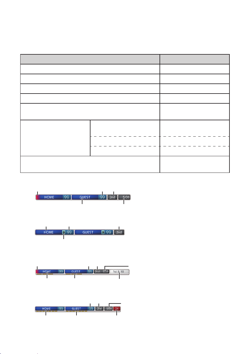
Score Display................................................................................................................................... 3
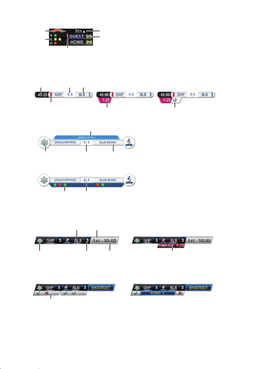
Selecting the Scoreboard Type................................................................................................. 3
Selecting a Position to Display the Scoreboard ........................................................................ 4
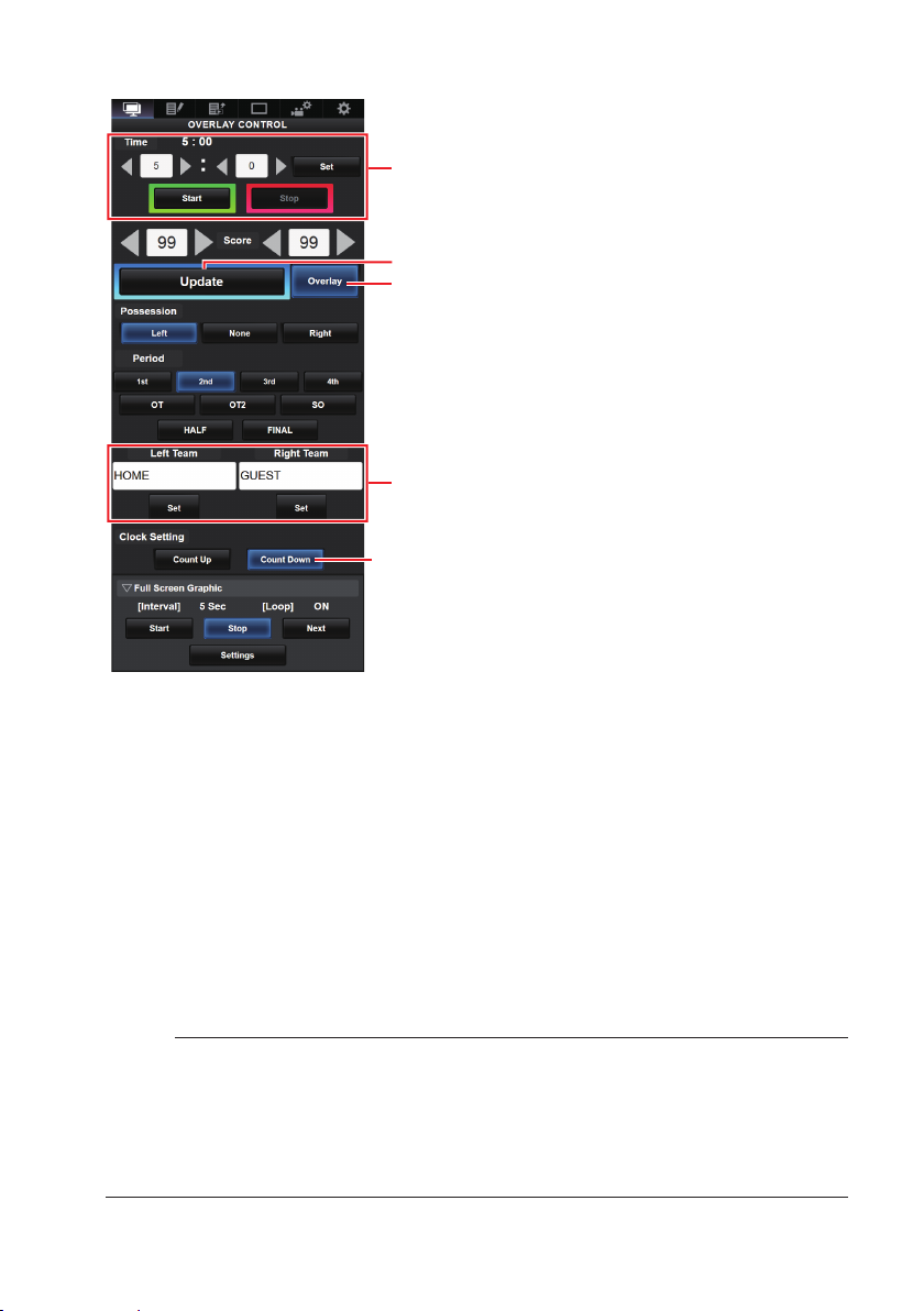
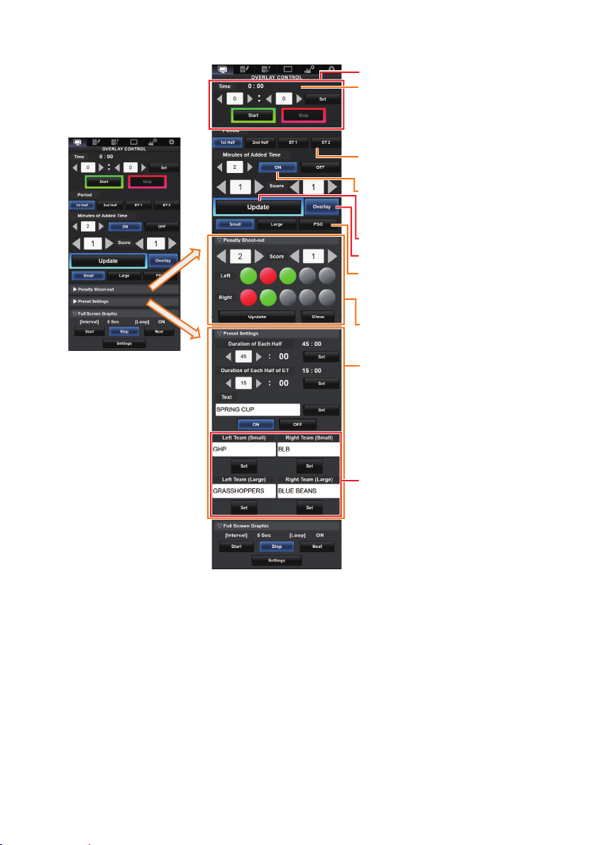
Inputting Scoreboard Data ....................................................................................................... 6
Setting the Team Display........................................................................................................ 14
Specifying Texts Directly from Web Browser................................................................... 14
Importing an Image Containing the Team Name and Logo ............................................. 14
Deleting an Imported SDP File ....................................................................................... 16
Selecting a Destination to Display the Overlay ....................................................................... 17
Ingesting the Scoreboard Data Automatically ........................................................................ 17
Preparing for Connection................................................................................................ 17
Menu Setting .................................................................................................................. 18
Score Sync............................................................................................................................. 22
Preparation..................................................................................................................... 22
Creating the Replica List................................................................................................. 22

3
Score Display
This camera recorder enables single-camera sports coverage producing real-time score
overlays on recorded or streamed HD video. This function is available when the recording
resolution is 1920x1080 or 1280x720.
\Selecting the Scoreboard Type
Memo:
●When displaying Football (Soccer) or Hockey (Ice Hockey), import an SDP le to
the camera recorder in advance. Create these SDP les in the SDP Generator.
(AP14 “Importing an Image Containing the Team Name and Logo”)
Next, select the imported SDP les from [Main Menu] → [Overlay Settings] → [Layout].
Press the [MENU] button of the camera recorder to display the menu screen, and then
select a scoreboard type in [Main Menu] → [Overlay Settings] → [Type]. Then press the
[MENU] button to close the menu screen. The types that are selectable include Type 1,
Type 2, Football (American Football), Basketball, Baseball, Football (Soccer) and Hockey
(Ice Hockey).
However, the selectable types may vary according to the [Layout] setting.

4
\Selecting a Position to Display the Scoreboard
The scoreboard can be displayed at the following positions on the screen. Create an
SDP le with the desired display position in the SDP Generator and import the le to the
camera recorder. (AP14 “Importing an Image Containing the Team Name and Logo”)
Type Overlay Location
Type 1 Top, Bottom
Type 2 Top, Bottom
Football (American Football) Top, Bottom
Basketball Top, Bottom
Baseball Top Right, Bottom Right, Top
Left, Bottom Left
Football (Soccer)
Small Top Right, Bottom Right, Top
Left, Bottom Left
Large Bottom (not changeable)
Penalty Shoot-out Bottom (not changeable)
Hockey (Ice Hockey) Top Right, Bottom Right, Top
Left, Bottom Left
●Type 1:
Offense Team Indicator
Team Name Remain Time
Points Scored Period
●Type 2:
Games Won
Team Name Points Scored Reset
●Football (American Football):
Offense Team Indicator
Team Name TOL
Remain Time
Down & Distance
Points
Scored Period
●Basketball:
Team Name TOL
Remain Time
Shot Clock
Points Scored Period

5
●Baseball:
Inning
Team Name; Points Scored
Runner
Count
Offense Team Indicator
●Football (Soccer):
Select [Small], [Large] or [Penalty Shoot-out] in the Overlay Control web screen.
Time
[Small]
[Large]
[Penalty Shoot-out]
Points
Scored
Text
Points
Scored
Team Logo (Small)
Team Logo (Large)
Goal/Miss
Team Name (Large)
Points Scored
Additional Time Minutes of Added Time
Team Name (Small)
●Hockey (Ice Hockey):
Select [Small] or [SHOOTOUT] in the Overlay Control web screen.
[Small]
[SHOOTOUT]
Rounds 1 to 3 Rounds 4 and later
Points Scored Remain Time
Team Logo
Goal/Miss
Power Play
Team Name Period
●None: Does not display

6
\Inputting Scoreboard Data
1Following the “Connecting to the Network” in the “INSTRUCTIONS” manual stored
in the Mobile User Guide (http://manual3.jvckenwood.com/pro/mobile/global/index.
php), connect a network device such as a smartphone or a tablet with the camera
recorder via network. Then, launch a web browser on the network device.
2 Enter the following URL in the address eld of the web browser.
http:// “IP address of the camera recorder”
Example: http://192.168.0.1
To find the “IP address of the camera recorder”, press the [STATUS] button of the
camera recorder to display the status screen and then use the cross-shaped button
(tu) to display the [Network] screen.
3 Enter the username (jvc) and password (default: 0000) on the login screen. And then
press the Overlay Control icon at the top left corner of the screen or the [Overlay
Control] button to display the score input screen.
4 The web browser displays the following screen according to the [Type] setting of the
camera menu.
Data other than numerical values will be reected immediately on the score overlay
without having to press the [Update] button.

7
●Type 1
C[Overlay] Button
DTeam Name (for text input)
Clock Count Direction
Count Up: Increase
Count Down: Decrease
B[Update] Button
ATime
A Time
The start time entered is reflected on the score overlay by pressing the [Set]
button.
B [Update] Button
Reects numerical values such as score and distance on the score overlay.
C [Overlay] Button
Turns the score overlay on or o.
D Team Name (for text input)
If the SDP file selected in the menu item [Main Menu] → [Overlay Settings] →
[Layout] of the camera recorder contains more than one team name image, this
item is grayed out and text input is disabled.
E [Display] Button
Displays or hides a specied area.
Memo:
●Press the [DISPLAY] button of the camera to switch the display mode if the
overlay is dicult to see due to the camera operation graphics.
●When the camera is live streaming while recording, the update interval of the
time display may not be constant. When this happens, reduce the resolution of
the live streaming.

8
●Type 2
C[Overlay] Button
DTeam Name (for text input)
B[Update] Button
●Football (American Football)
C[Overlay] Button
DTeam Name (for text input)
B[Update] Button
ATime

9
●Baseball
E[Display] Button
DTeam Name (for text input)
B[Update] Button
●Basketball
C[Overlay] Button
DTeam Name (for text input)
B[Update] Button
E[Display] Button
[Reset1]/[Reset2] Button
for Shot Clock
Resets the value (in seconds)
set below
[Set] Button
Confirms the value (in seconds)
when Reset1/2 button is pressed
ATime

10
●Football (Soccer)
C[Overlay] Button
B[Update] Button
Time (Left):
Currently displayed match time.
Penalty Shoot-out:
Use when “PSO” is selected.
Period:
Can be changed only when the clock
is stopped.
Display Type:
[Small] Button: Small display
[Large] Button: Large display
[PSO] Button: Penalty Shoot-out display
Minutes of Added Time:
Displays the additional time granted only
during additional time if “ON” is selected.
Time (Right):
Currently displayed additional time.
Displayed only during additional time.
A
Time
DTeam Name (for text input)
Preset Settings:
Items to be set before the match.
Set the duration of each halftime, texts to
be displayed in the Large display, and
team names to be used in the Small and
Large displays.

11
●Hockey (Ice Hockey)
Power Play:
Entering the penalty time displays the
power play state that corresponds to it.
Display Type:
[Small] Button: Small display
[SHOOTOUT] Button: Shoot-out display
SHOOTOUT:
[Round 1-3] Tab: For round 1 to 3
[Round 4+] Tab: For round 4 and later
C[Overlay] Button
B[Update] Button
ATime
DTeam Name (for text input)

12
Additional time display for Football (Soccer):
The display of additional time toggles on and off automatically depending on the
elapsed time of [Time] and the status of [Period]. Whether a match is in additional time is
determined by the setting values of [Duration of Each Half] and [Duration of Each Half of
ET] of [Preset Settings]. The display example is as follows.
Example) Duration of Each Half: “45:00”, Duration of Each half of ET: “15:00”
Period Time Time Display
1st Half 1:23
46:23
2nd Half 46:23
91:23
ET 1 91:23
106:23
ET 2 106:23
121:23

13
Power play for Hockey (Ice Hockey):
Depending on the state of the penalty time, power play is automatically displayed or
hidden. The display example is as follows.
Penalty Time Time Display
Left Team Right Team
Display Position Display Time
Penalty
1
Penalty
2
Penalty
1
Penalty
2
0:00 0:00 0:00 0:00 ―
0:00 0:00 Time C 0:00 Time C
0:00 0:00 Time C
Time D
Time C or D (the
smaller of the two)
Time A 0:00 0:00 0:00 Time A
Time A 0:00 Time C 0:00 Time A or C (the
smaller of the two)
Time A 0:00 Time C
Time D
Time A, C or D
(the smallest of the
three)
Time A Time B 0:00 0:00 Time A or B (the
smaller of the two)
Time A Time B Time C 0:00
Time A, B or C
(the smallest of the
three)
Time A Time B Time C
Time D
Time A, B, C or D
(the smallest of the
four)

14
\Setting the Team Display
Team names can be displayed by one of the following ways.
●Specifying texts directly from web browser
●Importing an image containing the team name and logo
Specifying Texts Directly from Web Browser
Enter the texts in the Overlay Control web screen. Available characters are as follows.
However, text cannot be entered when using a SDP le containing team name images.
!”#$%&'()*+,-./0123456789:;<=>?@ABCDEFGHIJKLMNOPQRSTUVWXYZ[\]^_`abcdefghijklmno
pqrstuvwxyz{|}~¡¢£¤¥¦§¨©ª”¬®¯°±²³´µ¶•¸¹º”¼½¾¿ÀÁÂÃÄÅÆÇÈÉÊËÌÍÎÏÐÑÒÓÔÕÖרÙÚÛÜÝÞ
ßàáâãäåæçèéêëìíîïðñòóôõö÷øùúûüýþÿĞğİıŒœŞşŠšŸŽžƒˆ˜–—‘’‚““”†‡•…‰‹›€™
Importing an Image Containing the Team Name and Logo
To display a team name with logo or a team name that contains characters that are not
available for input, an image can be imported to the camera recorder in place of text
input for display at the team name area of the score overlay. The data le (SDP le) to be
imported can be generated by an SDP Generator, a PC/Mac application. A maximum of
30 teams can be registered. For information on SDP Generator, please contact your local
dealer or download from our website.
https://www.jvc.net
Caution:
●Please check the content and font licenses of the image before use.
1 Copy the SDP le generated by the SDP Generator to the root folder of an SDHC/
SDXC card. Specify a name for the SDP le that is not longer than 63 alphanumeric
characters with a “sdp” extension.
Example: [overlay1.sdp]
2Insert the SDHC/SDXC card in which the SDP file is copied into slot A or B, then
select [Main Menu] → [Overlay Settings] → [Import User Layout].

15
3The SDP files in the root folder of the SDHC/SDXC card are displayed (max.
8 files per slot). However, if the file name is long and cannot be displayed on
the menu screen, the file will be displayed with part of the file name omitted.
Select an SDP le to import from the list of displayed SDP les.
4Select an import destination from areas 1 to 4 to start importing. If you select an
area where a le name is already displayed, a conrmation screen asking whether
to overwrite will appear. It will take about 20 to 30 seconds to complete the import.
“Complete” will be displayed at the end. A gray display area indicates insufficient
space and it cannot be selected. Select another area or delete SDP les that are not
required in advance in [Main Menu] → [Overlay Settings] → [Delete User Layout].
Caution:
●Do not turn off the power of the unit during import. You may lose the import
data.
In the case of import failure, the following messages may appear.
Error Message Status Action
Failed To Read File
From Media!
• SD card is defective.
• SDP le data is corrupted..
• Use other SD card.
• Use the SDP file generated by
the SDP Generator.
No User Layout
Exists.
• SDP le data is corrupted..
• The camera recorder version
is old and an unknown SDP
le has been imported.
• Use the SDP file generated by
the SDP Generator.
• Update the rmware for the
camera recorder to the latest
version.
Failed To Write File
To The Camera!
There may be a problem with
the camera.
Please contact the local dealers in
your area.
Import Error! An internal error has occurred. Please contact the local dealers in
your area.

16
5 When import is successful, the name of the imported SDP le will be added to the
[Main Menu] → [Overlay Settings] → [Layout] item. Select an SDP le name suitable
for overlay. If a valid SDP le is not imported to the camera recorder, or if the SDP
le imported does not match the recording format of the camera recorder, the [Type]
item will be displayed as “None” and grayed out. Import a correct SDP le with [Import
User Layout].
6 Select the team name to display in [Main Menu] → [Overlay Settings] → [Left Team] (*)
or [Right Team] (*).
* This menu item name can be changed in the SDP Generator settings.
Deleting an Imported SDP File
You can delete an imported SDP le.
1 Select [Main Menu] → [Overlay Settings] → [Delete User Layout].
2 Select an SDP le to delete. The blue line at the background of the SDP le name
indicates that the le is applied for the current overlay.
Memo:
●The imported SDP le cannot be deleted in [Main Menu] → [System] → [Reset All].
Please use this function to delete.

17
\Selecting a Destination to Display the Overlay
When [Type] in the Overlay Settings is set to a value other than “None”, you can select
whether to overlay the image onto HD recordings or HDMI/SDI external outputs.
[Main Menu] → [Overlay Settings] → [Output]
HD Recording
For setting whether to overlay a scoreboard on HD recording clips.
HDMI/SDI
For setting whether to overlay a scoreboard on external video outputs such as HDMI,
SDI and AV Output terminal.
Memo:
●When the recording format is “HD+Web”, the scoreboard display is always overlaid
on the “Web” recording clip.
●The scoreboard display is always overlaid on live video streaming.
●When [HDMI/SDI] is set to “Off”, [AV Set] → [Video Set] → [Display On TV] will
become “---”.
●The settings cannot be changed during recording or live streaming.
●When using the SD side cut output function while recording score overlay in HD
mode, the left and right edges of the score display may be cropped.
●When the recording format is “HD”, the overlay display settings are also reected
when switched to the Time Stamp output.
\Ingesting the Scoreboard Data Automatically
By using a scoreboard solution supplied from Sportzcast, the camera can ingest
scoreboard data automatically. This enables the updating of the scoreboard display
without having to manually enter the scores from the Web screen. Please contact the local
dealers in your area on the Sportzcast solution.
Preparing for Connection
To connect to the Sportzcast cloud service, select “Cloud” in the [Server Settings] (A
P18).
Meanwhile, connection to a Scorebot that is connected to a local network can be
configured using [Search for a local server] (AP19). Start search after powering on
Scorebot and connecting it to the same network as the camera recorder.

18
Menu Setting
[Main Menu] → [Overlay Settings]
Sportzcast
Select “Connect” to connect to the Sportzcast server congured below.
Memo:
●“Connect” cannot be selected if network connection is not established.
●Server connection switches to “Disconnect” when moving to a mode other than
record mode or when the power is turned o.
[Main Menu] → [Overlay Settings] → [Sportzcast Settings]
Server
For selecting the Sportzcast server to connect to.
Server Settings
For setting the Sportzcast server.
Cloud/Server1/Server2/Server3
* The name that is selected in [Alias] is displayed individually.
■ Alias
For setting a name to distinguish the settings of this camera recorder. The name
set in this item will be displayed as the [Server] option.
* The default value is “Cloud/Server1/Server2/Server3”.
* You can enter up to 31 characters and ASCII characters.
■ Address
For setting details such as the host name and the IP address of the server.
* Enter not more than 127 characters using single-byte alphanumeric characters (a
to z, 0 to 9), single-byte hyphen [-], or dot [.].
■ Broadcast
To connect 3 or more camera recorder units to Scorebot at the same time, set this
to “On”. The broadcast setting of Scorebot also needs to be turned on. For details
on how to congure Scorebot, please consult Sportzcast directly.

19
Search for a local server
Search for the local server (Scorebot) that is connected to the local network using the
wizard, and set the selected Scorebot in [Server Settings]. Before doing so, make sure
that both Scorebot and the camera recorder are connected to the local network with the
same subnet.
1From the list of search results, select the Scorebot to connect and press the right (u)
button of the cross-shaped button.
2Details of the selected Scorebot will be displayed. Check the information and press
the right (u) button.
3 Once the connection is successfully established, a conrmation screen appears.
Press the right (u) button.
4 Select [Server Settings] of the destination for saving and press the right (u) button.
5 Enter the [Alias] name to save and press the right (u) button.
6 After the connection complete screen appears, press (●) of the cross-shaped
button to close the menu screen.
Memo:
●If connection to a Scorebot has already been established, search cannot be
executed until it has been disconnected.
●Old settings in [Server Settings] at the destination for saving will be overwritten.
●Connection is established automatically after exiting the wizard, and the settings
in [Server] switch to the connected [Server Settings].

20
License Name
For setting the license name provided by Sportzcast.
Please note that you cannot use a license name you have already used in another
camera.
BOT Number
For setting the BOT number provided by Sportzcast.
Channel
For setting the channel provided by Sportzcast.
Score Input Source
When [Sportzcast] is set to “Connect”, select whether to obtain subsequent score
information from the server or enter the information manually from the Web screen.This
is useful when you want to enter only some information manually.
Memo:
●The [Display] and [Overlay] buttons on the Web input screen are always enabled
regardless of this setting.
Display Order (Home)
For selecting whether to display the score information of the home team acquired
from the Sportzcast server at the left, right, top or bottom of the screen. For Baseball,
however, the information is always displayed at the bottom of the screen regardless of
this setting.
●First: Displays at the left or top of the screen.
●Last: Displays at the right or bottom of the screen.
Team Name
For selecting the data reference source for the team name.
Shot Clock
For selecting the data reference source for the shot clock.
Others
For score information other than the above stated, select the data reference source.
This manual suits for next models
2
Table of contents
Other JVC Camcorder manuals

JVC
JVC GR-D70EK Administrator Guide

JVC
JVC GR-D650AA User manual

JVC
JVC GR-SXM303AS User manual

JVC
JVC GR-AX761 User manual

JVC
JVC GZ-MG27USM User manual

JVC
JVC GZ MG555 - Everio Camcorder - 5.4 MP User manual

JVC
JVC GR GR-DVL307 User manual

JVC
JVC GZ-MG27AA User manual

JVC
JVC GY-HM200 User manual

JVC
JVC GR-AX275 User manual

JVC
JVC Camcorder User manual

JVC
JVC GYHD110U - Camcorder - 720p User manual

JVC
JVC GZ-MS230AG User manual

JVC
JVC GR-AX860 User manual

JVC
JVC GR-D93US User manual

JVC
JVC GR-SXM335 User manual

JVC
JVC GZ MG37u - Everio Gseries Hard Disk... User manual

JVC
JVC CYBERCAM GR-DVF31 Setup guide

JVC
JVC GR-AXM240 User manual

JVC
JVC LST0984-001A User manual