manuals.online logo
Brands
  1. Home
  2. •
  3. Brands
  4. •
  5. JVC
  6. •
  7. Camcorder
  8. •
  9. JVC GY-X2B User manual

JVC GY-X2B User manual

JVC
Instructions
3-CCD
COLOR
VIDEO
CAMERA
WITH
S-VHS
VTR
GY-X2B
QUICK
USE
GUIDE
Table
of
Contents....
WRDOK
asissasessscsieievescéaed
senaecedanessoves
oes
Adjustment
before
Shooting
................ccseccrerees
Back
FOCUS
n.sessccssesecscecesasaiscscecescectscsssccascsase¥es
Intemal
Filter..........cecceceee
ae
VTR
Setup/Tape
Format
...........cscesesecsessescerseee
White
Balance/FAW
........scsseccsssssessseserserseccsnes
31
Shooting
Operation
Basic
SHOOting
...........ccsccssscscsesessseessesseseoeseeaes
33
|
Edit
Point
Search
............:sccesscsscsssessesssecesseersees
37
Playback
and
Tracking
...........sssscssereceeseesesseers
36
|
Quick
Recording
(ALC
+
FAW
+
Auto
Iris
+
Record)............0.
35
in
Case
of
Difficulties
..................scccccsscessssesssseeees
49
Advanced
Functions
VTR:
=
Auto/Quick
Editing
...........ssesseeees
38
Insert
Editing
Review
Playback
.........ccsecseseseneeee
38
Time
Code
Generator
(SA-R200)......
Camera
:
Electronic
Shutter
.................
os
Normal
Auto
White
Balance
..............
DA ee
emo
eeeneresacccounenccconersevenoneoeuons
oonenreceevcereecencees
Zebra
Exposure
Indication
Camcorder
Indications,
Controls,
Connectors
Camera
COntrOls
ssusssswssnsnsencnnncnene
a
VTR
Controls
.......
VTA
INICALOLS
........cseccceseesesensecesssncssotsssescossesers
Audio
Monitor, Control,
indicators
........
roe
On
Screen
Status
and
Auto
Display
..................
Input/Output
:
Video,
Audio,
Power
......
a
Camcorder
Front
........ccsscsssscesesserseees
Viewfinder
............0008
Warning
Functions
......
Preparation/nstaliiation
.....
36
Cassette
Loading,
Eject...
seesessssssseseees
LONS
MOUNTING
.........cesseccsesessscscseesesersorseseeserecs
Power,
Battery/AC
Adapter
............scssseceees
Microphones
..............:cessssesee
sate
Tripod
MOUNHiNg
...........cscssccssesersecsessesseresanense
ee
VIQWHNGOR
scsccssscescescccizscecessicsandecaasendezedisvonsivassers
Specifications,
Accessories,
Dimensions
.....
50-52
For
Customer
Use:
Enter
below
the
Serial
No.
which
is
located
on
the
top
frame.
Retain
this
information
for
future
reference.
Model
No.
GY-X2B
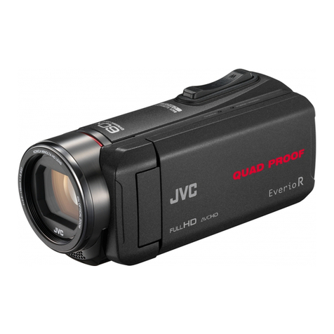
The
photograph
shows
the
GY-X2B
video
camera
Serial
No.
with
an
optional
lens
(YH13X7.5K12).
FO
rc
Te
eR
ON
NE
LEER
eae
me?
WARNINGS
j
CAUTION
f
RISK
OF
ELECTRIC
SHOCK.
CAUTION:
TO
REDUCE
THE
RISK
OF
ELECTRIC.
SHOCK,
O
NOT
REMOVE
COVER
(OR
BACK).
NO
USER-SERVICEABLE
PARTS
INSIDE.
REFER
SERVICING
TO
QUALIFIED
SERVICE
PERSONNEL.
The
lightning
flash
with
arrowhead
symbol,
within
an
equilateral
triangle
is
intended
to
alert
the
user
to
the
presence
of
uninsulated
"dangerous
voltage”
within
the
product's
enclosure
that
may
be
of
sufficient
magnitude
to
constitute
a
risk
of
electric
shock
to
persons.
The
exclamation
point
within
an
equilateral
triangle
is
intended
to
alert
the
user
to
the
Presence
of
important
operating
and
maintenance
(servicing)
instructions
in
the
literature
accompanying
the
appliance.
Due
to
design
modifications,
data
given
in
this
instruction
book
are
subject
to
possible
change
without
prior
notice.
WARNING:
TO
PREVENT
FIRE
OR
SHOCK
HAZARD,
DO
NOT
EXPOSE
THIS
UNIT
TO
RAIN
OR
MOISTURE.
AVERTISSEMENT:
POUR
EVITER
LES
RISQUES
D'INCENDIE
OU
D'ELECTROCUTION,
NE
PAS
EXPOSER
L'APPAREIL
A
L'HUMIDITE
OU
A
LA
PLUIE.
LITHIUM
BATTERY
REPLACEMENT
MARKING
REPLACE
BATTERY
WITH
MATSUSHITA
ELECTRIC
(OR
PANASONIC)
CR2025.
USE
OF
ANOTHER
BATTERY
MAY
PRESENT
A
RISK
OF
FIRE
OR
EXPLOSION.
LITHIUM
BATTERY
DISPOSAL
MARKING
WARNING
—
THE
BATTERY
USED
IN
THIS
DEVICE
MAY
PRESENT
A
FIRE
OR
CHEMICAL
BURN
HAZARD
IF
MISUSED.
DO
NOT
RECHARGE,
DISASSEMBLE,
HEAT
ABOVE
100°C
(212°F)
OR
INCINERATE.
DISPOSE
OF
USED
BATTERY
PROMPTLY.
KEEP
AWAY
FROM
CHILDREN.
DO
NOT
DISASSEMBLE
AND
DO
NOT
DISPOSE
OF
IN
FIRE.
information
for
Canada
This
product
complies
with
D.O.C
limits
(C.R.C.,
C.
1374)
pertaining
to
class
B
digital
apparatus.
Renseignement
pour
Canada
Ce
produit
est
conforme
aux
normes
du
M.D.C.
(C.R.C.,
ch.
1374)
s'appliquant
aux
appareils
numériques
de
classe
B.
POWER
SYSTEM
This
color
video
camera
should
be
used
with
12
V
DC
only.
CAUTION:
To
prevent
electric
shocks
and
fire
hazards,
do
NOT
use
other
than
specified
power
source.
Systéme
d'alimentation
Cette
caméra
vidéo
couleur
ne
doit
étre
utilisée
que
sur
tension
continue
de
12
V.
Attention:
Pour
éviter
tout
risque
d'incendie
ou
d'électrocution,
n'utilisez
aucune
autre
source
d'alimentation.
Changes
or
modifications
not
approved
by
JVC
could
void
the
user's
authority
to
operate
the
equipment.
CONGRATULATIONS
Thank
you
for
purchasing
the
JVC
GY-X2B
3-CCD
Full
Size
Professional
S
Camcorder.
To
gain
maximum
benefit
from
the
camera,
it
is
suggested
that
you
study
this
booklet
carefully.
After
reading,
retain
it
for
future
reference.
FEATURES
e
S-VHS
High-Resolution
Pictures
S-VHS
recording
circuitry
for
high-quality
pictures
with
hori-
zontal
resolution
of
more
than
400
lines.
e@
Hi-Fi
Stereo
Sound
With
rotary
FM
Hi-Fi
audio
heads,
the
GY-X2B
offers
Hi-Fi
Stereo
sound
recording
with
superior
frequency
response,
greater
dynamic
range,
and
improved
wow
&
flutter
perform-
ance.
2-channel
linear
audio
with
Dolby*
noise
reduction
system
is
also
provided.
*
Dolby
noise
reduction
manufactured
under
license
from
Dolby
Laboratories
Licensing
Corportion.
“DOLBY”
and
the
double-D
symbol
are
trademarks
of
Dolby
Laborato-
ries
Licensing
Corporation.
e
Rugged
Diecast
Body
Rugged
integrated
construction
with
newly-designed
diecast
aluminum
body
for
improved
durability
and
reliability.
e
Easy-to-see
LCD
Panel
with
Backlight
A
built-in
LCD
panel
is
provided
for
display
of
lap
time/tape
counter,
remaining
tape
time,
audio
levels,
battery
duration,
hour
meter,
warning
indications.
Backlight
capability
allows
easy
checking
even
in
dimly-lit
places.
e
Rotary
erase
head
and
AEF
function
permit
noiseless
as-
semble
editing.
e
Auto
Review
function
for
quick
recording
review
e
Insert
recording
function
for
replacing
video
and
Hi-Fi
sound
on
a
pre-recorded
tape
e
Built-in
speaker
for
sound
monitoring.
e
With
the
optional
SA-R200
time
code
generator,
time
code
recording
is
possible.
e
JVC
utilizes
newly
developed
broadcast
1/2
inch
CCDs
with
high
750
line
resolution,
high
sensitivity
of
F8
at
2000
Ix
and
a
superb
signal
to
noise
ratio
of
62
dB
at
0
dB
gain.
ee
e
LOLUX
captures
scenes
never
before
possible
because
of
low
lighting
conditions.
In
this
mode
the
CCD
chip
is
maximized
for
low
light
sensitivity.
This
Super
Sensitivity
is
ideal
for
special
shooting
conditions
with
almost
no
lighting.
Good
color
balance
is
maintained
even
down
to
1.5
Ix
illu-
mination.
@
Quick
record
mode
for
emergency
recording
with
a
single
touch
of
a
button.
Exposure
is
controlled
automatically
with
variable
shutter,
gain
and
iris.
White
balance
is
also
continu-
ously
adjusted.
@
Multi-Zone
Auto
Iris
Detection
Circuit
Multi-zone
iris
detection
circuit
ensures
optimum
iris
posi-
tion
even
in
backlit
conditions
or
when
a
bright
subject
moves
in
a
frame.
Over-under
level
switchable.
e
Electronic
shutter
with
speeds
of
1/100,
1/250, 1/500,
1/1000
and
1/2000
second
e
Safety
Zone
Indication
In
addition
to
center
mark
on/off
capability,
safety
zone
indication
for
the
16
:
9
screen
format
is
available.
e
Zebra
pattern
video
level
indication
CONTENTS
QUICK
USO
GUIdE
........eecesssessessssscsecsssssssrssesssssssesesssesssnsesseassacey
Safety
Precautions
.....
JVC
Product
Safety...
FOARUFOS
....ssessrsrsscccescesssssreessreee
Standard
System
Configuration
.........sscssssssseesseesessssseservese
.
Precautions
Setfaty)
2
ssc
ssnssedsocdecceucossnsasteutiecadeussaselssoveiusiashussebcessissdancevasteoseSeiveaseds
4
Handling
we
4
Moisture
.....
we
4
CD
aise
ad
Gain,
Noise
.......
wae
D
Video
cassettes
....
woe
Tape
Protection
......s.ceccscecssssssssessssessssssesssussssvssssetecessvessssassesecsess
5
Controls,
Indicators,
Connectors
OVGIVIOW.:-isverssssssovsascsasesnsssssvansavactebcbcasesssuassbacsdaasgeretevsvendeccdvdesperace
6
Camera
head
front
section
..
eit
Camera
controls
...........00
a
8
MTF
CONUS
cs
cssisccessenscassssschsrcossnesccescsedbsassisacsuvatecosdcoscractedioestadecs
10
VTR
S@t
UP
COMPOS
.....scsescssssesssesessesessesssssceesetesssssssssscsessessnecese
12
VTR
indicators/AUdIO
CONTTOl
............ssscsescssssssessssessssecsestscscsescneees
14
Input
and
Output:
Video,
Audio,
Power
........ccscssssscscessessecceceseee
16
Lens
(YH13X7.5K12)
.......eesesscscssscssessseesessesesecsercesasecarsesesersensers
18
VIGWEINGER
........s.sssserosscsscoscsssssssssssonssssssenseesseesessssenansesenesssessecesavess
19
Status
display
..........ecsssssesssssssssssssecsssesesssssssersnsssessescssseasates
20
Automatic
display
0.0...
csssssssecscsssecsssessssseesesesssssssesssecsevesses
21
Warning
functions
Camera
WAIMingS
......ssssscsececssscssesessssecsecsesssersessssessssesesesacsas
22
VTR
SYMPtOMs
INdICATIONS
..........ssesessssesesesssssssssssvenrerstsceeeees
23
Precaution/Installation
VIOWHINGGN:
sacs
ssscsvssieeecanecievsdissassancd
cciaveteesterecaseisectevcstesebc
hedeeccee
24
LQMS
=
csassnossosseciesesacenscasnntssescensascdsseseszescvesiselandneddsavcossteroveesesiissec’
25
Microphones
MICTOPHONG
uu...
sssessssecscscsssssersesscsssesssessesersussssssvesscacsnseecnenezes
25
Other
Microphone
.........sscsssscsssssssecessessesseseseveresessseesssecesssaveere
26
Power
supply
;
Battery
(NB-G1/Flat
shape
type)
..............cccsessessssssssecesecsenes
27
AC
adapter
oo...
eecesessssceessseeaes
Tripod
mounting
..............00
Cassette
loading,
ejecting
Adjustments
Before
Shootin
Camera
control
settings
for
adjustment
............scccccsssssssesesseeesaee
29
Set
ViOWfinder
..........cssessesscecccsesssssessesecesssseserssssssssseeveecessceserereces
30
Adjusting
back
fOCUS
«00.0.0...
ssssssssssssseeeessscssssssessesecesectensecessersees
30
Set
internal
filter...
essssssssessecsesssetsssssssssscsesesesecesssseseseacesees
31
Set
white
Dalance
oc
esssesessssseesesecessssssessevsessesssecceverseacererses
31
SeOt
UP
VOR
sc
cssssecectescccesseuscoutclesacoiosciessasiasedsansestocscs
ceusbocneselioaies
32
Format
setti
we
B2
The
audio
level
is
indicated
in
the
viewfinder.
Highly
reliable
XLR
connectors
for
audio
input.
Input
circuit
utilizes
balanced
input
system
that
is
less
affected
by
exter-
nal
noise.
e
Retake
function
with
edit
searching
for
easy
checking
of
recordings
at
normal
speed
e@
Built-in
genlock
circuit
for
system
synchronization
e
With
its
dual
output
system,
the
camera
output
can
be
connected
directly
to
an
external
recorder.
e
Y/C
output
connector
e
Earphone
jack
e
Color
temperature
conversion
filters
for
“3200
K”,
“5600
K”
and
“5600
K
+
ND”
e
Variable
scan.
Flicker
bars
in
the
display
image
of
computer
monitors
are
caused
by
the
differing
scan
rate
of
the
computer
monitors.
The
Variable
Scan
function
can
minimize
this
effect
by
tun-
ing
the
camera
shutter
speed
to
the
precise
scan
rate
of
the
display
screen.
The
smail
increments
range
from
60.1
Hz
to
2084.6
Hz
(1/60.1
sec
to
1/2084.6
sec).
Page
Shooting
Operation
Normal
shooting
operation
.........ccsessssscssssesessssssns
sesseesssssseressenece
33
Quick
recording
..........cse0
..
35
Enhanced
ALC
system.....
w
35
Tape
playback
...........cccccsses
..
36
Tape
tracking
(Playback)
...........
a
36
Tape
timer/Time
code
display
...
wae
87
“Retake”
Edit
point
Search
.......ccsscsssssceccsesescsesenassescssscsesseces
sees
37
Advanced
Functions
VTR
Auto
edit
(Seamless
in
camera
editing)
.........0esssssccsesessseceee
38
Auto
setting
(seamless,
but
slow)
............
.
38
Quick
setting
(Quick,
but
not
seamless)
..
»
38
Effects
of
Quick
or
Auto
SettingS
.........ccsue
cee
wa
38
Auto
review
(Review
+
Auto
or
Quick
edit
ready)
....
..
38
INSOrt
OUTING
.........cesscecsecsssesssssescetssesesesssesstewe
senses
wae
89
PIQUE:
MONCN
0
scsccssssassenssvsccasaanebeeusavaccussssasicsstvandca
tovacrbusssssaesbcas
40
Camera
LOMIK
ssisics
cusicssceauensscasssesnssvascacestidave
stascicbcsuaulathn
Sucaeosincaneaielee
40
Iris
Auto/Manual
iris...
eecsssessessssssseeesesssue
seseeesesssssseseues
41
Multizone
iris
........
Electronic
shutter
..
Operation
.............
as
Variable
SCAM
uu...
sssscsscsscsstecsessessssenscesssorsun
assersctsienssesence
Studio
use
CONNECTION
.........secessescoesessessscsssoessonsseesasosoran
sotesssccsesessse
ses
Genlock
............000
fis
Video
level
indication
0.0...
.secsesssessessssssssssssrne
eesteesssecarsasesess
SA-R200
Time
code
generator
Basic
UNCON
o.oo.
es
eesescsscssessssessccssssssesssecatsan
anetecstsessusensease
VITC
i
ccctcsscstanssess
Controls/indicators
Operation
TIME
COdE
SEttING
.....ccscecessecsesssessesssessssesson
eoeretessecessnsas
ees
User
bits...
eaavans
SA-R200
specifications
.........cccessessssscsecssseotnn
one
Remote
trigger/Zoom
servo
control
(HZ-ZS13BU)
....
JVC
service
function
in
Case
of
Difficulties
........
Accessory
list
............00.
GY-X2B
Specifications...
WAAOX:
scccecsdeveeceseesecdasasss
SYSTEM
CONFIGURATION
The
standard
configuration
of
the
GY-X2B
is
as
shown
below.
STANDARD
CONFIGURATION
Camera
head
Provided
microphone
1.5-inch
viewfinder
Tripod
base
KA-510
PRECAUTIONS
SAFETY
PRECAUTIONS
e
Use
only
the
optional
NB-G1
Battery
Pack
or
the
optional
AA-P250
AC
Power
Adapter.
e
Do
not
modify
the
unit
or
operate
it
without
cover
panel
to
prevent
danger.
@
When
there
is
any
abnormality
(abnormal
noise, smell,
smoke,
etc.)
with
the
unit,
immediately
turn
the
power
off
and
con-
tact
your
nearest
JVC-authorized
service
agent.
e
Do
not
damage
or
fray
the
power
cord.
Otherwise,
this
will
cause
leakage
or
electrical
shock.
e
if
the
camera
is
not
going
to
be
used
for
an
extended
period
of
time,
leave
the
power
cord
disconnected
for
reasons
of
Safety.
e@
If
there
is
a
danger
of
being
struck
by
lightning
during
out-
door
shooting,
evacuate
to
a
safe
place
immediately.
HANDLING
PRECAUTIONS
e
Supply
voltage
Make
sure
that
the
power
is
between
11.5
V
and
15
V
DC.
If
the
power
voltage
is
too
low,
abnormal
color
and
increased
noise
could
occur.
Do
not
exceed
15
V
DC
in
any
case,
or
the
unit
could
be
damaged.
e
Where
there
are
strong
electromagnetic
waves
or
magnet-
ism,
for
example
near
a
radio
or
TV
transmitter,
transformer,
motor,
etc.,
the
picture
may
contain
noise
and
the
colors
may
be
incorrect.
e@
When
a
wireless
microphone
or
wireless
microphone
tuner
is
used
near
the
camera,
the
tuner
could
pick
up
noise.
In
such
a
case,
select
another
channel.
e
Cleaning
the
body:
Wipe
body
with
a
dry,
soft
cloth
(such
as
cheesecloth).
When
it
is
extremely
dirty,
soak
the
cloth
in
a
solution
of
neutral
detergent,
wring
it
out
and
then
wipe.
To
prevent
deformation
of
the
body,
etc.
and
to
avoid
opera-
tion
hazards,
do
not
allow
volatile
liquids
such
as
benzine
and
thinner
to
touch
the
body,
and
do
not
wipe
it
with
a
cloth
soaked
in
such
a
liquid.
If
the
equipment
is
soiled
with
water,
oil,
solvent,
etc.,
wipe
over
with
soft
cloth
or
cotton
first,
then
clean
with
gauze,
etc.
soaked
in
denatured
alcohol.
VTR
e
Influence
of
vibrations
When
tapes
are
played
back
in
a
place
subject
to
excessive
vibrations,
color
pictures
may
not
be
obtained.
@
Moisture
condensation
prevents
use
of
the
unit.
e
You
have
observed
that
pouring
a
cold
liquid
into
a
glass
will
Cause
drops
of
water
to
form
on
the
glass’s
outer
surface.
This
same
phenomenon
occurs
on
the
head
drum
of
a
video
recorder
when
the
recorder
is
moved
from
a
cool
place
to
a
warm
place,
after
heating
in
a
cold
room,
under
extremely
humid
conditions
or
in
a
place
directly
subjected
to
the
cool
air
from
an
air
conditioner.
e
Moisture
on
the
head
drum
can
cause
severe
damage
to
the
video
tape,
and
can
lead
to
internal
damage
to
the
recorder
itself.
e
If
moisture
condensation
occurs
on
the
head
drum,
a
con-
densation
waming
appears
in
the
recorder
LCD
and
the
unit
enters
the
Stop
mode,
unable
to
function.
In
such
a
case,
wait
for
a
few
hours
until
the
indicator
disappears.
Operate
Off
Circuit
with
Battery
Operation
e
When
the
battery
is
depleted
in
battery-powered
operation,
the
OPERATE
indicator
starts
blinking
with
red
color
and
a
warning
beep
is
heard
from
the
earphone.
If
you
continue
operation,
the
Operate
Off
function
is
executed
automatically
to
protect
the
unit.
If
this
happens,
replace
the
battery
with
a
fully-charged
one.
e
‘f
the
Operate
Off
function
is
activated
in
the
Record-Pause
mode,
the
tape
remains
loaded
due
to
the
auto
recording
lock
function.
LENS
e@
The
camera
lens
should
be
protected
externally
with
a
Clear
or
UV
filter
against
accidental
scratching,
touching
or
dirt.
The
external
lens
cap
should
be
used
whenever
possible.
e@
When
the
lens
is
changed,
take
special
care
to
avoid
con-
taminating
the
inner
lens
surface
and
camera
gate/optical
block
area
with
moisture
or
dust.
CAMERA
CCD
Smear
and
Blooming
@
Due
to
the
physical
structure
of
the
CCD
in
this
camera
it
is
possible
to
induce
vertical
streaking
or
smear
when
shooting
an
extremely
bright
light
source.
e
Another
effect
is
the
expansion
of
light
around
a
bright
light
or
object
called
Blooming.
Just
as
you
protect
your
image
against
lens
flare
(internal
lens
reflections);
please
be
careful
when
shooting
a
bright
light
source.
Smear
(Vertical
pale
streaking
appearing
at
high
luminous
object)
High
luminous
object
(Electric
light,
sunlight,
etc.)
Blooming
(Blurring
in
highlight)
Monitor
screen
Gain,
Noise
@
Higher
levels
of
output
gain
result
in
a
decrease
in
the
signal
to
noise
ratio,
possibly
resulting
in
a
noisy
picture.
Moire
or
Aliasing
e
Shooting
stripes
or
fine
patterns
may
cause
a
jagged
effect
or
a
banding
in
fine
mesh
patterns.
Try
repositioning
the
lens
zoom
to
change
the
frequency
of
the
detail
information
and
eliminate
the
distortions.
@
High
Temperatures
e
High
temperatures
can
cause
CCD
sensor
pixels
to
malfunc-
tion
with
the
effect
of
white
dots
in
the
image.
This
condition
could
damage
the
CCD,
and
certainly
raises
the
“fixed
pattern”
noise
level
that
CCDs
have
thus
giving
a
noisy
picture.
VIDEO
CASSETTE
HANDLING
e
The
GY-X2B
employs
only
cassette
carrying
the
S-VHS
and
the
VHS
marks.
e
Recording
onto
prerecorded
tapes
automatically
erases
the
previously
recorded
video
and
audio
signals.
e
An
inverted
cassette
cannot
be
inserted.
e
Do
not
load
and
unload
the
cassette
repeatedly
without
al-
lowing
the
tape
to
run
at
all.
This
will
slacken
the
tape
and
thereby
damage
it.
e
Make
certain
before
loading
the
cassette
that
the
tape
is
not
slackened.
If
there
is
any
slack,
turn
the
supply
gear
on
the
cassette
in
the
direction
of
the
arrow
to
take
up
slack.
e
The
cassette
is
equipped
with
a
safety
tab
to
prevent
acci-
dental
erasure.
When
the tab
is
removed,
recording
is
im-
possible.
If
you
wish
to
record
on
a
cassette
whose
tab
has
been
removed,
use
adhesive
tape
to
reseal
the
slot.
e
To
avoid
excessive
exposure
to
dust
and
fingerprints,
do
not
open
the
front
tape
cover.
e
It
may
not
be
possible
to
record
on
the
first
5-second
section
of
a
new
tape
due
to
winding
margin.
Turn
supply
side
reel
in
the
direction
of
arrow.
Safety
tab
to
prevent
erroneous
erasing
Storage
of
Cassettes
e
Avoid
exposing
the
cassettes
to
direct
sunlight,
keep
them
away
from
heaters.
e
Avoid
storing
the
cassettes
in
humid
or
dusty
places.
e
Do
not
drop
the
cassettes.
Do
not
expose
them
to
violent
vibrations
or
shocks.
e
Do
not
expose
the
cassettes
to
strong
magnetic
fields
(near
a
motor,
transformer
or
magnet).
e
Place
the
cassettes
in
cassette
cases
and
position
them
verttically.
Tape
Protection
e
Do
not
leave
the
unit
in
the
Record-Pause
mode
for
too
long
to
avoid
discharging
the
battery
and
to
protect
the
tape.
e
When
using
this
unit
as
a
camera
alone,
remove
the
cassette
to
protect
the
tape.
e
To
protect
the
tape
in
the
Record-Pause
mode,
tape
tension
is
slackened
automatically
and,
after
about
30
minutes,
drum
rotation
stops
and
then,
“OPERATE”
LED
will
be
blink
with
green
color.
e
To
re-start
recording,
press
the
REC
button,
or
turn
the
camera
section’s
operation
switch
in
the
order
of
“VTR
ST-
BY”
—
“SAVE1”
—
“ST-BY”
to
engage
the
Record-Pause
mode.
e
During
extended
still
playback,
tape
action
is
as
follows.
Elapsed
time
Approx.
3
min.
30
sec.
Advances
a
few
frames.
Approx.
7
min.
Advances
a
few
frames.
Approx.
10
min.
30
sec.
Stops
completely.
Pee
eee
ae
eee
TE
eT
ED
CONTROLS,
INDICATORS
AND
CONNECTORS
Carrying
handle
@
Battery
holder
@
Edit
search
button
©
Monitor
speaker
@
Battery
release
button
@
[QUICK
REC]
Quick-recording
start/stop
trigger
Use
this
button
as
a
quick-recording
start/stop
trigger.
Recording
starts
immediately
when
this
button
is
pressed,
with
ALC
and
auto-iris
forcibly
engaged.
White
balance
will
also
be
automatically
adjusted
accordingly.
In
this
mode,
the
electronic
shutter
and
variable
scan
mode
cannot
be
used.
Variable
shutter
is
automatically
engaged.
Pressing
this
button
again
or
button
@
releases
the
quick-
recording
mode
and
engages
the
Record-Pause
mode.
Use
this
function
only
in
an
emergency.
Allow
10
seconds
or
more
after
the
power
has
been
switched
on,
otherwise
this
function
will
not
operate
correctly.
©
[VTR]
Recording
start/stop
trigger
Use
this
button
located
on
the
camera
head
front
section
and
the
lens
as
a
normal
shooting
start/stop
trigger.
Recording
will
start
about
2
seconds
after
the
button
has
been
pressed.
Pressing
it
again
engages
the
Record-Pause
mode.
(See
illustration
on
next
page.)
Accessory
shoe
———
—_
@
ane
|
Aws
ei
———
[|
—
|
|
ON
|
sT-BY
REC
PAUSE
Yes
|
ON
|
saves
Lights
stop
{|
No
|
Yes
~—||
Yess
No
STOP
No
Quick-recording
start/stop
trigger
Power
switch
and
Power
indicator
Quick
recording
|
VTR
display
@
[EDIT
SEARCH]
Edit
search
buttons
Allow
forward
or
reverse
search
at
normal
speed
while
in
the
Record-Pause
mode.
Use
this
function
to
determine
the
start
point
of
a
retake.
The
search
picture
can
be
viewed
on
the
viewfinder
screen.
REV
:
For
reverse
search
at
normal
speed.
FWD
:
For
forward
search
at
normal
speed.
©
Monitor
speaker
Outputs
sound
according
to
the
setting
of
the
AUDIO
INPUT
SELECT,
AUDIO
OUT,
and
MONITOR
OUT
switches.
In
the
Playback
mode,
the
tape’s
playback
sound
can
be
moni-
tored.
Sound
level
can
be
adjusted
by
the
MONITOR
LEVEL
control.
Warning
beeps
are
also
emitted
from
this
speaker
together
with
the
monitor
sound.
(Waming
sound
level
cannot
be
adjusted.)
Connecting
an
earphone
to
the
EARPHONE
jack
defeats
sound
output
from
the
speaker.
CAMERA
HEAD
FRONT
SECTION
©
Cable
clamp
©
12-pin
lens
connector
@
Recording
start/stop
trigger
©
Battery
holder
Shown
here
is
the
standard
battery
holder.
This
can
be
used
for
Flat
shape
type
and
JVC
NB-G1
batteries.
The
4-pin
12
V
DC
connector
has
priority
over
this
battery
holder.
Other
manufacturer's
battery
holders
can
be
attached
in-
stead.
@
Battery
release
button
Open
the
cover
while
this
button
is
pressed.
©
[LENS]
12-pin
lens
connector
For
use
with
a
lens
having
a
12-pin
connector.
Pino.
Function
|
Pin
No.
Funcion
RET
switch
IRIS
position
VTR
start
GND
LENS
AUTO
IRIS
control
12
VDC
©
Cable
clamp
For
fixing
lens
cable,
etc.
®
Viewfinder
base
and
slide
retaining
ring
Attach
the
1.5-inch
viewfinder
to
this
base
and
secure
it
with
the
slide
retaining
ring.
|
sii
(
+
_—__——______-®
Filter
turret
Viewfinder
base
and
slide
retaining
ring
|
Viewfinder
connector
(6-pin)
i
i
>.
9
Lens
mount
ring
Video
level
indicator
on/off
switch
Auto
white
balance
switch
@®
[VF]
Viewfinder
connector
(6-pins)
Connect
the
viewfinder
cable.
@®
[FILTER]
Filter
turret
Selects
the
filter
setting
for
color
conversion
and
ND.
1.
(8200K):
For
shooting
indoors,
or
outdoors
when
illumi-
nation
is
insufficient.
2.
(5600K):
For
shooting
outdoors.
3.
(5600K
and
ND
filter):
For
shooting
outdoors
on
sunny
days.
®
Lens
mount
ring
For
retaining
the
lens.
@®
[ZEBRA]
Video
level
indicator
on/off
switch
Set
this
to
ON
to
obtain
the
video
level
indication
on
the
viewfinder
screen.
@®
[AUTO]
Auto
white
balance
switch
Push
the
switch
toward
“WHT”
to
initiate
the
auto
white
bal-
ance
procedure.
The
switch
need
not
be
pushed
continuously.
'
CAMERA
CONTROLS
©
Iris
correct
select
—_—uiig
switch
@
Status
display
mode
Select
switch/Safety
zone
mode
select
switch
ST-BY
SAVE!
SAVE2
©
[GAIN]
Sensitivity
select
switch
Electronically
boosts
light
sensitivity
when
there
is
insuffi-
cient
illumination
on
the
subject.
0dB
:
Normal
ea
Joos
dB
:
Boosted
to
approximately
3
times
eee
a
as
much
18
dB:
Boosted
to
approximately
8
times
as
much
LOLUX
gain
button
®
Shutter
speed
button
Variable
scan
mode
select
switch
White
balance
mode
select
switch
Camera/Color
bars
select
switch
®
[DISP.
SELECT]
Status
display
mode
select
switch
Switches
the
viewfinder
indications
of
the
camera's
setting
Status.
Push
it
up
to
switch
the
displays
as
follows.
ie
Display
0
—
Display
1
—
Display
2
4
See
“Status
Display’
on
page
20.
[ZONE]
Safety
zone
mode
select
switch
Selects
the
safety
zone
indication
on
the
viewfinder
screen.
Push
it
down
to
switch
the
safety
zone
indications
as
follows.
“OFF”
(no
indication),
to
“MODE1”,
“MODE2”
and
“MODE3”.
See
“Safety
Zone
Indication”
on
page
21.
@
[IRIS]
IRIS
CORRECT
SELECT
switch
IRIS
switch
can
be
used
to
adjust
the
exposure
system
to
over
or
under
exposure
by
about
a
half
F
stop.
OVER
for
continued
over
exposure
NORMAL
for
normal
exposure
UNDER
for
continued
under
exposure
Many
conditions
can
cause
the
detection
mode
to
expose
high
or
low,
such
as
back
lit
or
spot
lit
situations.
@®
[LOLUX]
LOLUX
gain
button
LOLUX
gain
gives
extremely
low
light
level
sensitivity
for
special
applications.
The
spec
is
the
equivalent
of
F1.4
at
1.5
Ix,
LOLUX
operation
takes
priority
over
normal
gain
operation.
Pressing
it
again
restores
the
previous
mode.
In
the
LOLUX
mode,
the
ALC
(automatic
level
control)
in
the
Quick-record-
ing
mode
is
not
available.
@®
[SPEED
-
(V.
SCAN)
-
SHUTTER]
Shutter
speed
button/Variable
scan
mode
select
switch
The
OFF
switch
position
engages
the
normal
1/60-second
speed.
Normally
use
this
speed.
The
ON
switch
position
engages
selected
shutter
speeds.
Turning
the
shutter
switch
ON
while
pressing
the
speed
button
engages
variable
scan.
Shutter
speed
button:
Each
time
this
button
is
pressed,
the
shutter
speed
changes
to
1/100,
1/250,
1/500,
1/1000,
1/2000,
then
back
to
1/100
second.
i
1/100
—
1/250
—
1/500
—
1/1000
—
1/2000
=
This
removes
blurring
when
shooting
fast-moving
objects.
To
return
to
1/60
second,
press
the
switch
to
OFF.
*
In
areas
with
a
50
Hz
power
line,
select
“1/100”
to
reduce
flickering
under
fluorescent
light.
*
When
powered,
the
shutter
speed
remains
the
same
as
selected
before
the
power
was
turned
off.
When
restarting
shooting,
be
sure
to
check
the
shutter
speed.
Variable
scan
mode:
*
Turning
the
shutter
switch
ON
while
keeping
the
speed
button
pressed
engages
the
variable
scan
mode.
To
change
the
shutter
speed,
release
the
speed
button,
then
press
it
again.
Each
time
the
button
is
pressed,
the
shutter
speed
changes.
Keeping
the
button
pressed
auto-
matically
advances
the
speed.
Even
if
the
power
is
turned
off,
the
selected
shutter
speed
is
retained
in
memory.
This
mode
is
used
for
shooting
images
on
a
computer
monitor
whose
scanning
speed
is
different
from
the
cam-
era’s
normal
shutter
speed.
This
mode
covers
vertical
scanning
frequencies
ranging
from
60.1
Hz
to
2084.6
Hz.
However,
it
cannot
respond
to
monitors
with
slower
scan-
ning
frequencies
(such
as
50
Hz).
*
Service
Information:
“AUTO
2"
position
can
be
alloted
to
“FAW”
(Full
Time
Auto
White)
by
changing
the
internal
switch
setting.
For
detail,
referto
“1.7
Switches
on
CP
board
-
@
ALC/FAW
switch”
in
page
1-4
of
the
service
manual.
:
[W.
BAL]
White
balance
mode
select
switch
AUTO
1,
AUTO
2:
White
balance
is
set
to
the
memory
auto-
matically
ajusted
with
switch
®.
White
balance
is
set
to
the
preset
stand-
ard
(corresponding
to
a
color
temperature
of
3200K
with
filter
control
set
to
1
and
5600
K
when
set
to
2).
Independent
white
balance
settings
can
be
stored
in
the
AUTO
1
and
AUTO
2
positions.
PRESET:
@
[MODE]
Camera/Color
bars
select
switch
Selects
the
recording
or
output
signal.
CAM:
Camera
signal
BARS
:
Color
bars
signal
VTR
CONTROLS
Top
—————————
cesar
|
g
oo
=
eo
JT
ir
2
2)
_
;__2
=
F
(TTS
@VTR
control
cover/uniock
Rec/Insert
button
@
Eject
button
Tally
lamp
@®
Stop
button
Tally
lamp
on/off
switch
@
Rewind/Search
button
Pause
button
@®
Play
button
Fast-Forward/Search
button
Bottom
Power
breaker
release
button
10
@®
VTR
control
cover/unlock
lever
This
cover
prevents
accidental
operations
while
shooting
and
prevents
entry
of
water
droplets
and
dust.
To
open
it,
Push
the
cover
up
while
keeping
the
lever
depressed.
Note
In
order
to
engage
the
fast-forward,
rewind,
or
play
modes
while
in
the
Record-Pause
mode,
first
press
the
Stop
but-
ton
to
engage
the
Stop
mode
and
then
select
the
desired
function.
®
LED
indicators
Lights
to
show
corresponding
operation
status.
®
[EJECT]
Eject
button
Press
to
eject
the
cassette.
it
will
take
about
10
seconds
for
the
tape
to
be
unloaded
and
the
cassette
ejected.
Press
this
button
only
when
the
unit
is
in
the
Record-Pause
and
Stop
mode.
The
cassette
cannot
be
ejected
if
the
power
supply
is
insuffi-
cient
(too
low
or
no
battery
power).
In
such
a
case,
replace
the
battery
pack
with
a
charged
one.
The
EJECT
button
can
be
pressed
even
when
the
VTR
section
is
covered.
LED
indicator
blinks
while
ejection.
@®
[STOP]
Stop
button
Press
to
cancel
the
Play,
FF,
REW,
Record
and
Record-
Pause
modes.
When
the
cassette
is
loaded
and
the
unit
is
in
Stop
mode,
the
LED
indicator
remains
lit.
@
[REW]
Rewind/Search
button
Press
to
rewind
the
tape.
When
pressed
while
in
the
Play
mode,
reverse
search
at
5
times
normal
speed
is
engaged.
If
this
button
is
pressed
and
held
in
the
Record-Pause
mode,
the
tape
is
played
back
for
review
in
the
reverse
direction
at
normal
speed.
@
[PLAY]
Play
button
Press
to
play
back
the
tape.
PLAY
LED
indicator
lights
while
playback
operation
takes
place.
If
it
is
Record-Pause
mode,
and
press
PLAY
button,
the
VTR
go
to
“REC”
mode.
®
[REC-INSERT]
Record/Insert
button
¢
Assemble
Record
Press
together
with
the
PLAY
button
@
to
engage
the
Assemble
Record
mode.
REC
and
PLAY
LED
indicators
light.
Press
the
STOP
button
to
stop
recording.
To
temporar-
ily
stop
recording,
press
the
PAUSE
button.
To
re-start
re-
cording
from
the
Record-Pause
mode,
press
the
PLAY
but-
ton
@.
*
Pressing
only
this
button
engages
the
Record-Pause
mode.
*
When
using
this
button
as
a
Record/Insert
button,
follow
the
procedures
shown
in
“Insert
recording”
on
page
39.
@
[REC
TALLY]
Tally
lamp
Lights
when
recording
starts
and
remains
lit
while
recording.
(Goes
off
when
in
the
Record-Pause
mode.)
Blinks
for
alarm
warning.
@
[TALLY
ON/OFF]
Tally
lamp
on/off
switch
ON
:
Tally
lamp
lights
or
blinks.
OFF
:
Tally
lamp
does
not
light.
Set
to
OFF
to
save
power.
@
[PAUSE]
Pause
button
Press
while
in
the
Play
mode
to
stop
the
tape
temporarily;
a
Still
picture
(with
noise)
will
be
obtained.
This
button
has
no
effect
while
in
the
Record
mode.
Repeated
pressing
of
this
button
plays
back
picture
in
single
frame
steps.
@®
[FF]
Fast-Forward/Search
button
Press
to
fast-forward
the
tape.
When
pressed
while
in
the
Play
mode,
forward
search
at
5
times
normal
speed
is
en-
gaged.
If
this
button
is
pressed
and
held
in
the
Record-Pause
mode,
the
tape
is
played
back
for
review
in
the
forward
direction
at
normal
speed.
Notes
for
VTR
operation
*
Because
this
unit
is
designed
especially
for
recording,
playback
and
still
pictures
may
have
some
noise
or
vibrate
vertically.
This
is
not
due
to
any
defect
of
the
unit.
*
During
search,
pictures
may
contain
some
noise,
vibrate
vertically,
or
become
monochrome.
This
is
not
due
to
any
defect
of
the
unit.
°
With
a
low-capacity
power
unit,
or
a
power
unit
whose
protective
circuit
characteristics
are
not
sufficient,
the
VTR
may
stop
because
of
a
shortage
of
power.
To
avoid
this,
use
specified
power
units.
*
No
audio
is
available
during
search.
¢
When
recording
in
the
VHS
mode
on
a
tape
previously
recorded
in
the
S-VHS
mode,
it
is
not
possible
to
search
or
edit
S-VHS
recordings.
@
[BREAKER]
Power
breaker
release
button
If
an
excessive
amount
of
current
flows
into
the
camera,
the
built-in
power
breaker
is
activated
to
cut
the
power
for
circuit
protection.
If
this
happens,
press
this
button
to
re-supply
the
power.
Notes
*
Before
re-supplying
power,
be
sure
to
check
the
cause
of
power
breakdown
and
take
appropriate
countermeas-
ures.
*
If
the
power
breaker
is
activated
often,
consult
your
JVC
dealer.
11
PER
MRED
GT
RNS
PLE
a
RET
PD
Ee
ROR
eT
EOC
VTR
SETUP
CONTROLS
©
Function
box
cover/uniock
lever
@
Audio
output
select
switch
@
Audio
monitor
select
switch
Audio
CH-1(L)
input
select
switch
Audio
CH-1(L)
input
level
select
switch
Audio
CH-2(R)
input
select
switch
Audio
CH-2(R)
input
level
select
switch
®
Tracking
control
volume
Dolby
NR
on/off
switch
@
AEF
select
switch
Hi-Fi
recording
on/off
switch
@
Auto
Review
on//ff
switch
Recording
level
select
switch
@
S-VHS
recording
select
switch
Video
output
select
switch
@®
Function
box
cover/uniock
lever
@
[MONITOR
OUT]
Audio
monitor
select
switch
To
open
the
cover,
pull
the
cover
toward
you
while
pushing
Selects
the
audio
output
of
the
monitor
speaker
and
ear-
the
lever
to
the
left.
phone
jack.
AUD1
:
To
monitor
audio
channel
1
(L).
@
[AUDIO
OUT]
Audio
output
select
switch
MIX
=:
To
monitor
mixed
sound
of
audio
channel
1
(L)
and
Selects
the
audio
output,
monitor
output,
and
level
meter
2
(R).
Mixed
with
each
channel
at
50
%.
indication.
AUD
2
:
To
monitor
audio
channel
2
(R).
Hi-Fi:
Outputs
Hi-Fi
audio.
NORM
:
Outputs
normal
audio.
12
®
[TRACKING]
Tracking
control
volume
Adjust
to
minimize
the
noise
in
pictures
and/or
Hi-Fi
audio
when
playing
back.
Normally,
set
to
the
center
position.
@®
[AEF]
AEF
select
switch
NORM
:
Automatic
Editing
Function
(AEF)
is
fully
activated
for
preroll
assemble
editing
with
clean
results.
In
this
position,
it
takes
longer
to
start
recording
from
the
Stop
mode.
QUICK:
AEF's
preroll
is
partially
activated
for
quick
record-
ing
start.
However,
scene
transitions
may
be
biurred.
See
“Automatic
Editing
Function
(AEF)”
on
page
38.
®
per
REVIEW]
Auto
Review
on/off
switch
:
When
the
Record-Pause
mode
is
engaged,
the
tape
reverse
plays
a
little,
then
the
rewound
portion
(ap-
proximately
3
sec.
worth)
is
played
before
entering
the
Record-Pause
mode.
Auto
Review
is
also
activated
by
the
lens
RET
switch.
OFF
:
The
Auto
Review
function
is
not
available.
See
“Auto
Review
Function”
on
page
38.
@
[S-VHS]
S-VHS
recording
select
switch
Selects
the
S-VHS
or
VHS
recording.
AUTO
:
Recording
mode
is
automatically
selected
accord-
ing
to
the
cassette
used.
S-VHS
is
selected
with
an
S-VHS
cassette
and
VHS
with
a
VHS
cassette.
OFF
:
Set
to
this
position
to
record
in
VHS
regardless
of
the
cassette
used.
@
[AUDIO
INPUT
SELECT
1/L
CAM/LINE]
Audio
channel-1
(L)
input
select
switch
CAM
:
Record
L-channe!
sound
from
the
6-pin
camera
mi-
crophone
input
@
.
LINE
:
Records
sound
from
the
XLR
3-pin
audio
channel-1
(L)
input
connector
®
.
@®
[AUDIO
INPUT
SELECT
1/L
+4/-60]
Audio
channel-1
(L)
Input
level
select
switch
+4
+
For
+4
dBs
line
level
input
-60
:
For
-60
dBs
microphone
level
input
@®
[AUDIO
INPUT
SELECT
2/L
CAM/LINE]
Audio
channel-2
(R)
input
select
switch
CAM
:
Record
R-channel
sound
from
the
6-pin
camera
microphone
input
®.
LINE
:
Records
sound
from
the
XLR
3-pin
audio
channel-1
(R)
input
connector
@
.
:
The
signal
selected
by
the
AUDIO
INPUT
SELECT
1/L.
switch
is
recorded
for
monaural
soundtrack.
AUD-1
@®
[AUDIO
INPUT
SELECT
2/R
+4/~60]
Audio
channel-2
(R)
input
level
select
switch
+4
:
For
+4
dBs
line
level
input
~60
:
For
-60 dBs
microphone
level
input
@
[DOLBY
NR
ON/OFF]
Dolby
NR
on/off
switch
ON:
Dolby
NR
circuit
is
activated
for
normal
audio
record-
ing
and
playback.
OFF
:
Dolby
NR
is
off.
Note
The
Dolby
NR
circuit
functions
only
with
normal
audio.
It
does
not
function
with
Hi-Fi
audio
regardless
of
the
posi-
tion
of
this
switch.
*
Dolby
noise
reduction
manufactured
under
license
from
Dolby
Labo-
ratories
Licensing
Corporation.
“DOLBY”
and
the
double-D
symbol
are
trademarks
of
Dolby
Laboratories
Licensing
Corporation.
@
[Hi-Fi
REC]
Hi-Fi
recording
on/off
switch
ON:
For
Hi-Fi
audio
recording.
OFF
:
Hi-Fi
audio
recording
is
not
available.
@
[REC
LEVEL]
Recording
level
select
switch
MANU
:
Recording
level
of
Hi-Fi
and
normal
audio
can
be
adjusted
with
the
AUDIO
REC
LEVEL
control
@
.
FIX
__:
The
recording
level
is
set
to
the
standard
fixed
gain.
Note
The
FIX
mode
is
not
an
automatic
gain
control
mode.
|
@®
[VIDEO
OUT]
Video
output
select
switch
NORM
:
Set
to
this
position
normally.
EDIT
:
When
using
the
unit
as
a
feeder
in
an
editing
sys-
tem,
set
to
this
position
so
that
the
signal
by-pass
the
noise
canceller
for
less
deterioration
in
tape
dubbing.
13
a
Rare
NN
ae
Ee
he
VTR
INDICATORS/AUDIO
CONTROL
@
Operate
lamp
acl
Reset
button
“3
auto
OFF
seevo_Locx
RESET
zt
@
Back
light
on/ott
————_f
<=
58.
98.
58.
88
SES
:
ce
Ct
User
bitTime
code/
switch
.
oe
a
=
ee
select
switch
@
Time
code
generator
Fa
select
button
control
panel
®
Monitor
level
control
volume
Recording
level
control
VTR
display
panel
14
Condensation
indicator
[DEW]
®
Servo
lock
“|
Hold
indicator
@
Auto
off
indicator
=
|
ee
de
VHS
indicator
@®
Counter
indicator
|
Servo
106
__
ey
eng
AUTO
OFF
SERVO
LOCK
DE
ee
ee
eC
ere
Ok oe
}
aad
rr]
=
indi
®
Lap
time
indicator
caw
fy
Mn
Te
MO)
9,
0.
=o
indicator
@
Tape
remain
oe
]
=
indicator
]
TAU
TUE
(A
Na
man
@
LTC
indicator
+808
5
=
Mn
TOM
fe
reece
ete
@
Time
counter
and
counter
mode
indicator
®
Battery
capacity
indicator
@
Audio
level
meter
@
[OPERATE]
Operation
lamp
Operation
:
Lights
green.
Warning
_ :
Lights
or
blinks
red.
See
“Warming”
on
page
23.
@®
[LIGHT]
Backlight
on/off
switch
ON:
Backlight
on.
OFF
:
Backlight
off.
To
save
power
in
battery-powered
operation,
set
to
OFF.
@
Time
code
generator
control
panel
When
installing
the
time
code
generator
SA-R200
(optional),
remove
this
cover,
and
set
switches
as
necessary.
Note:
Operation
switches
inside
the
cover
are
effective
only
when
the
optional
SA-R200
is
installed.
@®
[RESET]
Reset
button
Press
to
reset
the
tape
counter
and
lap
time
readout
to
00:00:00:00.
@®
[UB/TC/COUNTER]
User
bit/Time
code/Counter
select
switch
UB
:
Displays
User
Bits.
TC
:
Displays
the
time
code
reading.
COUNTER
:
Displays
tape
counter,
lap
time
counter,
or
re-
maining
tape
time
according
to
the
setting
of
the
SELECT
button
®
.
UB/TC
display
is
available
only
when
the
time
code
gen-
erator
SA-R200
(optional)
is
used.
When
it
is
not
in
use,
the
display
shows
the
counter
reading
only.
®
[SELECT]
Counter
select
button
Each
time
this
button
is
pressed,
the
display
changes
as
follows.
ee
COUNTER
~—
LAP
TIME
-»
T.
REMAIN
=a]
COUNTER
:
4-digit
tape
counter
reading
LAP
TIME
:
Lap
time
counter
reading
in
hours,
minutes,
and
seconds.
T.
REMAIN
:
Remaining
tape
time
in
hours
and
minutes,
in
1
minute
increments.
For
hour
meter
display,
unload
the
cassette
and
press
SELECT
and
REC
simultaneously.
Hold
for
about
3
seconds.
The
display
will
change
to
the
hour
meter
reading.
See
“Hour Meter
Display”
in
page
40.
@
[MONITOR
LEVEL]
Monitor
level
control
volume
Turn
to
adjust
the
sound
output
from
the
monitor
speaker
@
or
earphone
jack
@
.
Alarm
sound
level
is
fixed
and
cannot
be
adjusted
by
this
control.
@
[AUDIO
REC
LEVEL
1/L,
2/R]
Recording
level
controls
Turn
to
adjust
the
recording
level
of
Hi-Fi
or
normal
audio
channel-1
(L)/channel-2
(R),
with
the
recording
level
select
switch
®
set
to
MANU.
Adjust
the
controls
so
that
the
peak
level
shows
about
0
dB
on
the
audio
level
meter
@
.
@
[COUNTER]
Counter
indicator
Appears
when
the
counter
display
@
is
in
the
Counter
mode.
®
[LAP
TIME]
Lap
time
indicator
Appears
when
the
counter
display
@
is
in
the
Lap
time
mode.
@
[T.
REMAIN]
Tape
remain
Indicator
Appears
when
the
counter
display
@
is
in
the
Remaining
tape
time
mode.
@
Timer
counter
and
counter
mode
indicator
Displays
tape
counter/lap
time/remaining
tape
time/hour
me-
ter.
Also
displays
time
code
and
user
bits
when
the
time
code
generator
SA-R200
(optional)
is
installed.
@
[AUTO
OFF]
Auto
off
indicator
Appears
when
problems
occur
with
the
head
drum,
capstan,
reel
rotation,
mechanical
position,
etc.
See
“Warning”
on
page
23.
@
[SERVO
LOCK]
Servo
lock
indicator
Appears
when
the
drum
servo
or
capstan
servo
is
not
locked
to
the
input
video
signal.
See
“Warning”
on
page
23.
@
[DEW]
Condensation
indicator
Appears
when
condensation
occurs.
At
this
time,
no
opera-
tion
but
ejection
is
possible.
Wait
for
a
few
hours
until
the
indicator
goes
off.
@
[HOLD]
Hold
indicator
Appears
when
the
HOLD
button
is
pressed
with
the
SA-R200
time
code
generator
installed.
@
Audio
level
meter
Displays
Hi-Fi
or
normal
audio
level
in
recording
and
play-
back
as
selected
by
the
audio
output
select
switch
@
.
0
dB
is
the
standard
level.
@
[BATT]
Battery
capacity
indicator
Displays
remaining
battery
time
in
5
steps.
With
a
fully
charged
battery,
all
blocks
are
dispiayed.
When
the
number
of
blocks
drops
to
about
2,
the
OPERATE
lamp
@
and
tally
lamp
@
(while
shooting)
start
blinking.
Replace
the
battery,
See
“Warning”
on
page
23.
@
[S-VHS]
S-VHS
indicator
Appears
when
recording
or
playback
in
the
S-VHS
mode
is
engaged.
@®
[VITC]
VITC
indicator
Appears
in
VITC
recording.
(With
the
optional
time
code
generator
SA-R200)
@
[LTC]
LTC
indicator
Appears
in
LTC
recording.
(With
the
optional
time
code
gen-
erator
SA-R200)
15
INPUT
AND
OUTPUT
VIDEO
AUDIO
POWER
@
Earphone
jack
(mono)
@
[DC
INPUT]
DC
input
terminal
(4P)
Apply
12
V
DC
from
an
AC
power
adapter.
@
[EARPHONE]
Earphone
jack
(mono)
insert
an
earphone
with
@
3.5
mm
plug
to
monitor
the
sound.
Sound
output
from
the
monitor
speaker
is
defeated.
@
[AUDIO
INPUT
1/L,
2/R]
Audio
input
connectors
Audio
input
connectors
for
channel-1
(L)
and
channel-2
(R).
Input
level
can
be
selected
from
—60
dBs
and
+4
dBs
with
audio
input
select
switch.
GND
(Shielded)
HOT
COLD
@®
[AUDIO
OUT
1/L,
2/R]
Audio
output
connectors
(RCA)
Outputs
Hi-Fi
or
normal
audio
channel-1
(L)
and
channel-2
(R)
as
selected
with
the
audio
output
select
switch
®.
16
Audio
input
connector
(XLR
3P)
®
[Y/C
OUT]
YC
video
output
connector
(7-pin)
Outputs
the
S-VHS
Y/C
video
signal
selected
with
the
video
output
select
switch
@
.
|
Pin
No.
|
Function
|
PinNo.
|
Function
_|
C
signal
Y
signal
GND
(C)
®
[VIDEO
OUT]
Video
output
connector
(BNC)
Outputs
the
composite
video
signal
selected
with
the
video
output
select
switch
(@).
@
[SELECT]
Video
output
select
switch
Selects
the
video
signal
to
be
output
from
the
Y/C
@®
and
composite
@
video
signal
output
connectors.
CAM
:
Camera-through
signal
is
output
regardiess
of
the
VTR’s
operation
mode.
VTR
:
When
the
VTR
is
in
the
Play
mode,
the
playback
signal
is
output.
In
other
modes,
camera-through
sig-
nal
is
output.
OFF
:
Video
signal
output
from
either
connector
is
not
available.
To
save
power,
set
to
this
position
when
signal
is
not
necessary.
Cassette
holder
So
Yy
fs
WED
OUT
—¥/COLT
aug
oUt
©
Y
wa
ct
§@©@ee
Z
al.
|
wine
Video
output
select
switch
®
Cassette
holder
Accepts
either
an
S-VHS
or
VHS
cassette.
@®
[MIC]
Microphone
connector
(6-pin)
Connect
the
provided
microphone.
With
the
KA-A30
microphone
holder
(optional),
the
following
microphone
models
can
be
used.
*
M-K50
(mono;
VC-P740
optional
cable
required)
+
MV-P602
(stereo;
VC-P740
optional
cable
required)
«
MV-P612
(stereo)
Function
R
(Hot)
+9V
DC
GND
L
(Hot)
L
(Cold)
R
(Cold)
ee
Audio
output
connector
(RCA)
Y/C
video
output
connector
(7-pin)
‘®
Video
output
connector
(BNC)
Microphone
connector
(6-pin)
a
SC
phase
switch
SC
phase
control
H.
phase
control
External
reference
signal
input
connector
(BNC)
@
[SC
0°
120°
240°]
SC
phase
switch
Adjusts
the
color
subcarrier
phase
of
this
unit
in
three
steps
(0°,
120°,
and
240°)
with
respect
to
the
reference
sync
signal
input
to
connector
@
in
genlock
operation.
@
[SC
FINE]
SC
phase
control
Fine-adjusts
the
color
subcarrier
phase
of
this unit
with
re-
spect
to
the
reference
sync
signal
input
to
connector
®
in
geniock
operation.
@
[H
PHASE]
H.
phase
control
;
Adjusts
the
horizontal
sync
phase
of
this
unit
with
respect
to
the
reference
sync
signal
input
to
connector
@
in
genlock
operation.
@
[GENLOCK
INPUT]
External
reference
signal
input
con-
nector
(BNC)
Apply
a
composite
video
signal
or
black
burst
for
genlock
operation.
17
LENS
YH13X7.5K12
(optional)
@
FOCUS
ring
Manual
focus
ring.
Focus
distance
indicated.
@
ZOOM
lever/ring
Manual
zoom
ring
with
lever.
Deactivate
servo
zoom
with
switch
@.
Lens
zoom
length
is
indicated.
@
IRIS
ring
Manual
iris
ring.
Deactivate
auto
iris
with
switch
@.
@
BACK
FOCUS
ring
For
set-up
back
focus
adjustment
only.
Secure
with
the
screw
knob.
18
©
MACRO
button
(for
closeups)
Turning
the
zoom
ring
counterclockwise
(as
seen
from
the
front
of
the
lens)
while
keeping
this
button
(M)
pressed,
allows
closeup
shooting
at
up
to
5
cm
from
the
lens.
The
Normal
Focus
ring
should
be
left
set
at
infinity.
In
the
Macro
mode,
focusing
must
be
manually
adjusted
by
the
zoom
ring;
regular
focus
adjustment
and
zooming
are
not
possible.
@
IRIS
MODE
switch
A
:
Auto
iris
On
and
Remote
operation
M
:
Manual
iris
operation
@
MOMENTARY
AUTO
IRIS
In
manual
iris
mode
(M),
pushing
this
button
activates
the
auto
iris
function
while
it
is
held
down
only.
@
ZOOM
SERVO
control
Pushing
this
lever
in
the
W
direction
makes
the
lens
move
wider.
Pushing
this
lever
in
the
T
direction
makes
the
lens
move
tighter.
Pushing
harder
changes
the
speed
of
the
zoom.
Turn
this
lever
on
with
switch
@.
©
RETURN
(RET)
switch
Pressing
this
button
in
the
Record-Pause
mode
activates
Auto
Review.
The
tape
rewinds
for
a
few
seconds,
then
auto-
matically
plays
back
the
rewound
portion
and
re-enters
the
Record-Pause
mode
at
the
same
point.
Useful
for
checking
the
tape
section
just
recorded.
This
function
work
only
one
time
after
become
“REC-Pause”
mode
to
keep
tape
position
accuracy.
*
This
switch
has
no
effect
during
record
mode.
@
VTR
trigger
To
start
shooting
push
once.
To
stop
shooting
push
again.
@
REMOTE
ZOOM
control
connector
For
use
with
Studio
or
Teleconferencing
remote
control
units.
@
ZOOM
MODE
knob
SERVO
:
Servo
zoom
on
MANU:
Manual
zoom
mode
@®
FILTER
mount
screw
Mount
a
transparent
or
UV
filter
for
lens
protection
by
screw-
ing
this
screw
into
the
lens
hood’s
inner
groove,
or
the
front
of
the
lens.
Special-effect
filters
can
also
be
used.
Filter
diameter:
¢
Lens
hood
inside
:
82
mm,
0.75
mm
pitch
¢
Lens
front
:
72
mm,
0.75
mm
pitch
@®
Rear
lens
surface
Protect
with
special
cover.
@
Slide
lock
This
stopper
screw
prevents
the
viewfinder
from
coming
off
the
camera.
@
Viewtinder
shoe
Attaches
to
the
viewfinder
post
on
camera.
©
Viewfinder
cable
Connect
to
camera
socket
®
@
CONTRAST
Controls
the
level
of
viewfinder
contrast.
©
BRIGHT
Controls
the
level
of
viewfinder
brightness.
@
TALLY
switch
Set
this
switch
to
off
if
you
do
not
want
to
inform
the
subjects
by
the
Tally
light
that
they
are
being
recorded.
@
Tally
light
Lights
when
recording
is
in
progress.
©
Eyepiece
Blocks
light
from
viewfinder
screen
and
holds
eye
optics.
The
eyepiece
can
be
opened
to
view
the
screen
directly.
The
eyepiece
can
be
rotated
up
and
down
for
the
best
shooting
position,
or
opened
to
view
the
screen
directly.
©
Eyepiece
focusing
ring
Loosen
this
ring
and
move
the
eyepiece
backward
and
for-
ward
to
focus
the
viewfinder
for
the
operators
vision.
®
Viewfinder
slide
locking
ring
This
ring
on
the
camera
viewfinder
post
can
be
loosened
to
move
the
viewfinder
to
the
left
or
right
for
the
best
operator
comfort.
Warning:
Avoid
over-heating
if
a
light
is
mounted
on
the
camera
handle
accessory
shoe
!
Viewfinder
warning
indications
e
Viewfinder
Warning
Lights
@®
BATTERY
light
This
lights
red
when
battery
voltage
becomes
too
low
for
the
camera
to
operate.
®
REC/ALARM
light
This
light
shines
for
these
conditions.
Solid
Green
:
eWhile
recording
Blinks
Green
:
eWhile
the
VTR
prerolls
before
recording
elf
the
tape
is
finishing.
elf
the
VTR
maifunctions.
19
VIEWFINDER
STATUS
DISPLAY
ST-BY
SAVE!
SAVE2
Display
Mode-0
Display
Mode-1
STBY
Display
Mode-2
WHITE
BAL
AUTO1
0
IRIS
LEVEL
NORMAL
20
This
function
indicates
camera
and
VTR
status
on
the
view-
finder
screen.
Three
display
modes
are
available:
Mode-0,
Mode-
1
and
Mode-2.
Mode-0
is
engaged
when
the
power
is
turned
on.
To
select
the
mode:
7.
Push
the
DISP.
SELECT
switch
up.
Each
time
the
switch
is
pushed,
the
mode
changes
in
the
following
sequence.
ce
Mode-0
—
Mode-1
—
Mode-2
~
During
tape
playback
the
status
display
cannot
be
used.
Mode-0
:
Indicates
the
selected
functions
listed
below.
Selected
function
|
__1
__|_
IRIS
switch
set
to
OVER
or
UNDER
GorL
G:
GAIN
(+9,
+18)
L
:
LOLUX
:
SHUTTER
switch
set
to
ON
or
V-SCAN
ALC:
Auto
level
control
Mode-1
:
Push
the
DISP.
SELECT
switch
once.
VTR
mode
:
SAVE,
ST-BY,
REC,
QREC,
STOP
Remaining
tape
time
:
>120,
>90,
>60,
>30,
>20,
>10,
>5,
>4, >3,
>2, >1,
>0
Input
DC
voltage
—_:
Power
voltage
with
a
decimal
point
Audio
level
:
7
steps
_ -
-
_
+
—
_
(~18dB)
(-12dB)
(-6dB)
(-3dB)
(0dB)
(+3dB) (+6dB)
Mode-0
indications
are
displayed
in
Mode-1.
Mode-2
:
Push
the
DISP.
SELECT
switch
twice.
WHITE
BAL
:
AUTO
1,
AUTO
2,
PRESET,
FAW*
FILTER
:
3.2K,
5.6K,
5.6K+ND
SHUTTER
=:
NORMAL,
1/1
00,
1/250,
1/500,
1/1000,
1/2000
EEI*,
Variable
scan
speed:
1/60.1
—
1/2084.6
GAIN
:
0
dB,
9
dB,
18
dB,
LOLUX,
ALC*
IRIS
LEVEL
:
OVER,
NORMAL,
UNDER
*
In
Quick
Record
mode
FAW
=
Full
time
auto
white
balance
EE!
=
Extended
Electronic
Iris
(Variable
shutter)
ALC
=
Automatic
level
contro!
Me

Other JVC Camcorder manuals

JVC Everio GZ-GX1 Operating and maintenance manual

JVC

JVC Everio GZ-GX1 Operating and maintenance manual

JVC Enverio GZ-E245 Operating and maintenance manual

JVC

JVC Enverio GZ-E245 Operating and maintenance manual

JVC GR D 23 Manual

JVC

JVC GR D 23 Manual

JVC Everio GZ-HD620BEK Operating and maintenance manual

JVC

JVC Everio GZ-HD620BEK Operating and maintenance manual

JVC GZ-HD300BEK User manual

JVC

JVC GZ-HD300BEK User manual

JVC Everio GZ-VX815BEK Operating and maintenance manual

JVC

JVC Everio GZ-VX815BEK Operating and maintenance manual

JVC GR-SXM547 User manual

JVC

JVC GR-SXM547 User manual

JVC GR-AX710 User manual

JVC

JVC GR-AX710 User manual

JVC GR-DVF11 User manual

JVC

JVC GR-DVF11 User manual

JVC EVERIO GZ-HM690U Operating and maintenance manual

JVC

JVC EVERIO GZ-HM690U Operating and maintenance manual

JVC GZ-RX110 Operating and maintenance manual

JVC

JVC GZ-RX110 Operating and maintenance manual

JVC GR-SXM245 User manual

JVC

JVC GR-SXM245 User manual

JVC GR-AXM10 User manual

JVC

JVC GR-AXM10 User manual

JVC GZ-VX700BUS Operating and maintenance manual

JVC

JVC GZ-VX700BUS Operating and maintenance manual

JVC GZ-HD10AA User manual

JVC

JVC GZ-HD10AA User manual

JVC GC-PX100BE Operating and maintenance manual

JVC

JVC GC-PX100BE Operating and maintenance manual

JVC Everio GZ-E10 User guide

JVC

JVC Everio GZ-E10 User guide

JVC GZ-HM1S User manual

JVC

JVC GZ-HM1S User manual

JVC GR-DVM90U User manual

JVC

JVC GR-DVM90U User manual

JVC 2EN User manual

JVC

JVC 2EN User manual

JVC GR-DVF10 User manual

JVC

JVC GR-DVF10 User manual

JVC GY-LS300CHU User manual

JVC

JVC GY-LS300CHU User manual

JVC Everio GZ-MS150U Operating and maintenance manual

JVC

JVC Everio GZ-MS150U Operating and maintenance manual

JVC EVERIO GZ-HM670BUS User manual

JVC

JVC EVERIO GZ-HM670BUS User manual

Popular Camcorder manuals by other brands

PANAVISION Millennium DXL quick guide

PANAVISION

PANAVISION Millennium DXL quick guide

Samsung HMX-Q20BN user manual

Samsung

Samsung HMX-Q20BN user manual

Sony Handycam CCD-TR930 operating instructions

Sony

Sony Handycam CCD-TR930 operating instructions

Insignia NS-DV720PBL2 Quick setup guide

Insignia

Insignia NS-DV720PBL2 Quick setup guide

Audiovox 1287078 manual

Audiovox

Audiovox 1287078 manual

Canon Vixia HV30 instruction manual

Canon

Canon Vixia HV30 instruction manual

Panasonic Palmcoder PV-A16 operating instructions

Panasonic

Panasonic Palmcoder PV-A16 operating instructions

Sony Handycam DCR-DVD92E operating guide

Sony

Sony Handycam DCR-DVD92E operating guide

Spypen zemo user manual

Spypen

Spypen zemo user manual

Panasonic Palmcorder IQ PV-L606 user guide

Panasonic

Panasonic Palmcorder IQ PV-L606 user guide

Panasonic NV-MS5A operating instructions

Panasonic

Panasonic NV-MS5A operating instructions

ElectrIQ Wild1 user manual

ElectrIQ

ElectrIQ Wild1 user manual

Marshall Amplification CV730 user manual

Marshall Amplification

Marshall Amplification CV730 user manual

ElectrIQ iQ-SPEED user manual

ElectrIQ

ElectrIQ iQ-SPEED user manual

Mustek KiddyCam 135S user guide

Mustek

Mustek KiddyCam 135S user guide

Sony SPK-DVF2 operating instructions

Sony

Sony SPK-DVF2 operating instructions

Hitachi DZHV584E instruction manual

Hitachi

Hitachi DZHV584E instruction manual

MicroPower Technologies MPT2500 quick start guide

MicroPower Technologies

MicroPower Technologies MPT2500 quick start guide

manuals.online logo
manuals.online logoBrands
  • About & Mission
  • Contact us
  • Privacy Policy
  • Terms and Conditions

Copyright 2025 Manuals.Online. All Rights Reserved.