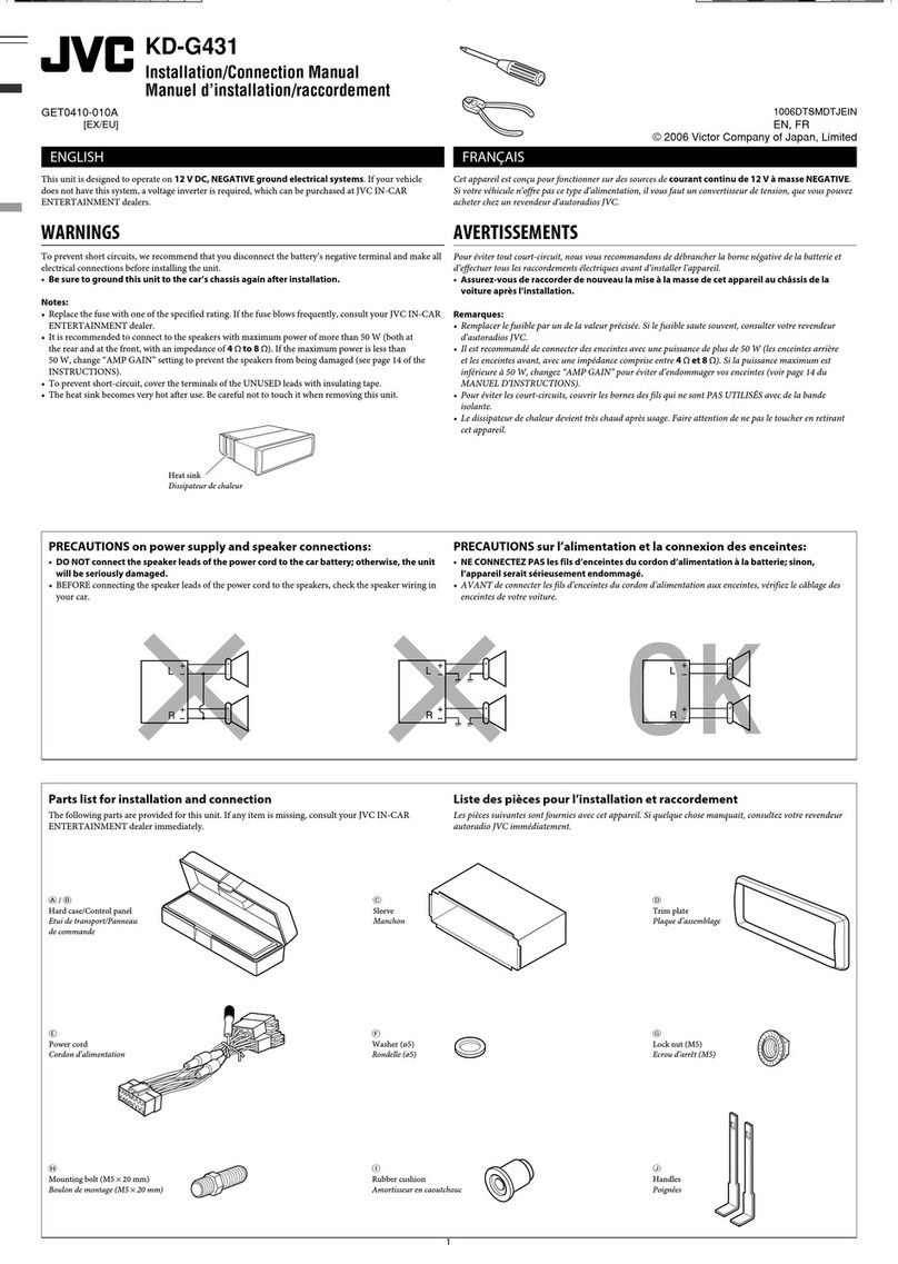
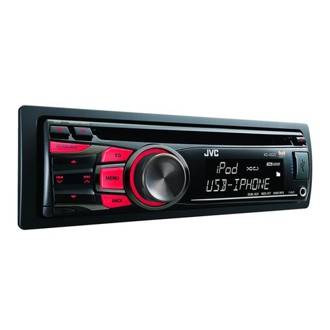
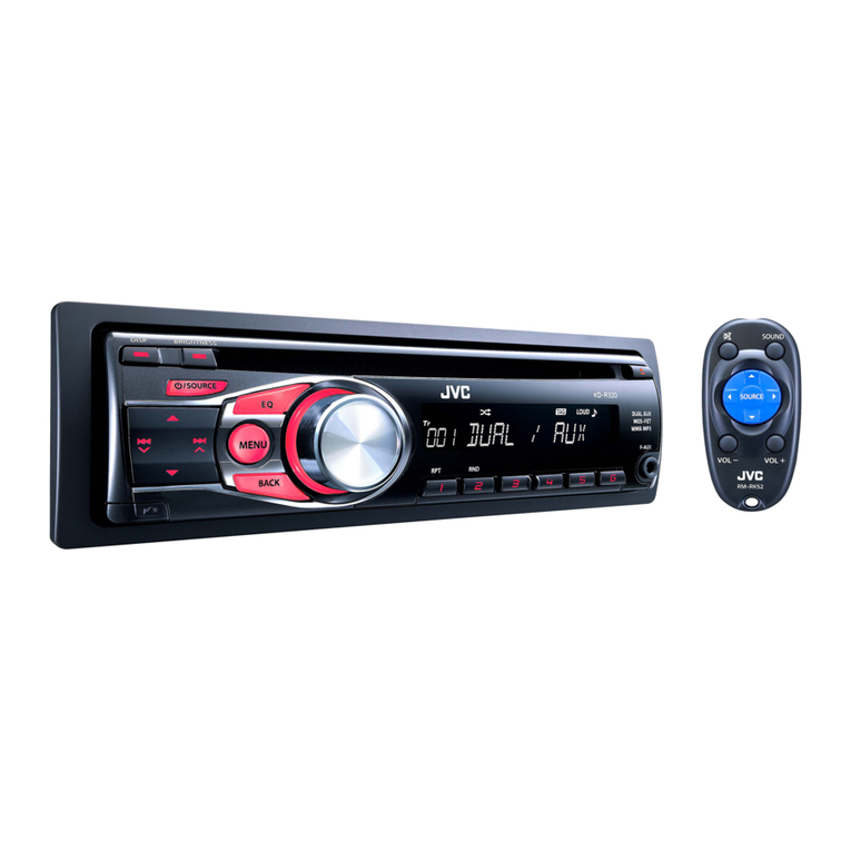
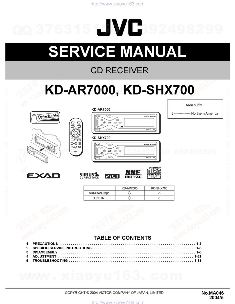
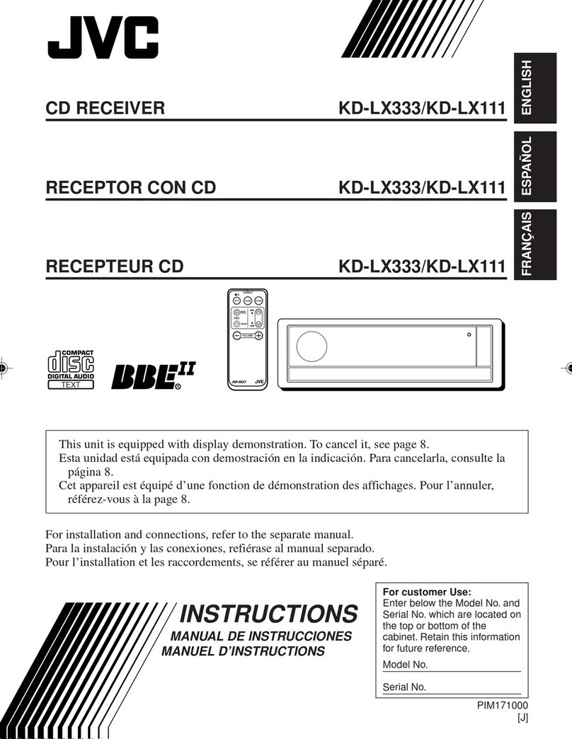
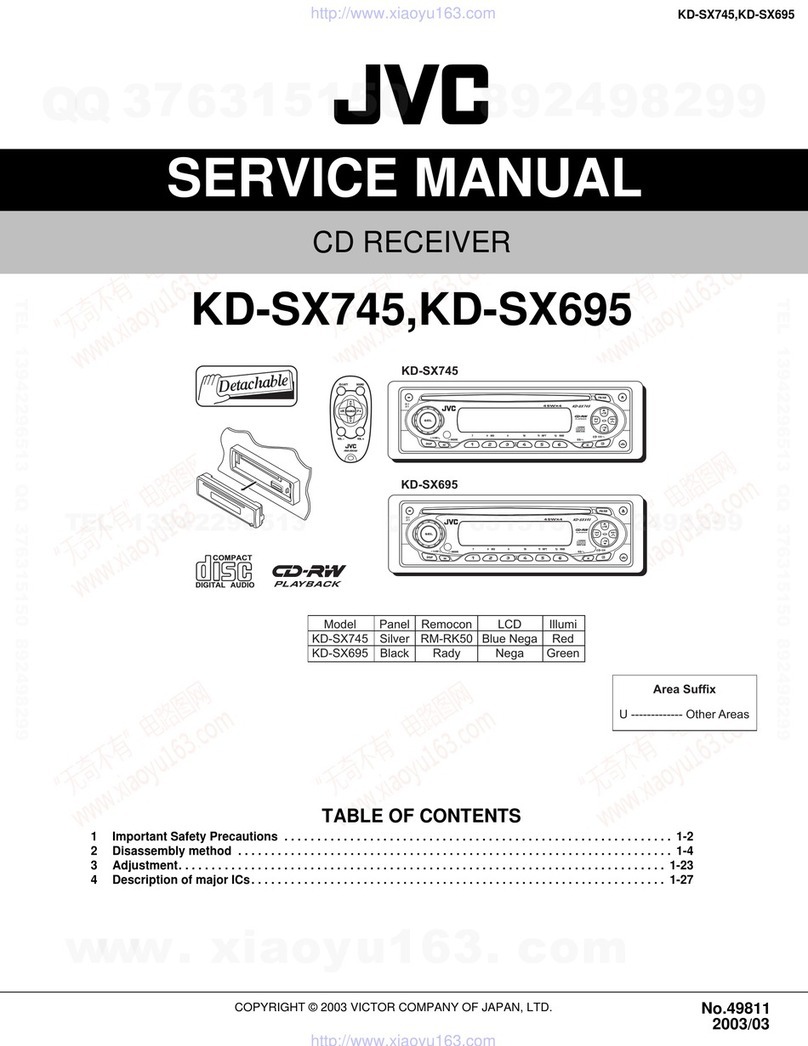
JVC KD-MX2900R User manual

SERVICE MANUAL
MD/CD RECEIVER
No.49554
Apr. 2000
COPYRIGHT 2000 VICTOR COMPANY OF JAPAN, LTD.
Printed in Japan
200004(O)
VICTOR COMPANY OF JAPAN, LIMITED
MOBILE ELECTRONICS DIVISION,10-1,1Chome,Ohwatari-machi,Maebashi-city,Japan
KD-MX2900R
(No.49554)
KD-MX2900R
KD-MX2900R
Area Suffix
E ---- Continental Europe
Contents
Safety precaution 1-2
Preventing static electricity 1-3
Instructions 1-4~22
Disassembly method 2-1
Adjustment method 2-17
Flow of functional operation
until TOC read 2-23
Maintena ce of laser pickup 2-24
Description of major ICs 2-25
Block diagram 2-50
Standard schematic diagrams 2-51
Printed circuit board 2-55~58
Parts list 3-1~19
This service manual is made from 100% recycled paper.
TP
RDS
SOUND
DISP
SSM
MO/RND
KD-MX2900R
PTY
MD/CD
CD
-CH
FM/AM
LOUD
789101112
/I
AT T
EXT
COMPACT
DIGITALAUDIO
TEXT
INT
RPT
DAB

!
CAUTION
Burrs formed during molding may be left over on some parts of the chassis. Therefore,
pay attention to such burrs in the case of preforming repair of this system.
Safety precaution
!
CAUTION
Please use enough caution not to see the beam directly or touch it in case of an
adjustment or operation check.

Preventing static electricity
1.Grounding to prevent damage by static electricity
Electrostatic discharge (ESD), which occurs when static electricity stored in the body, fabric, etc.is discharged,
can destroy the laser diode in the traverse unit (optical pickup). Take care to prevent this when performing repairs.
2.About the earth processing for the destruction prevention by static electricity
Static electricity in the work area can destroy the optical pickup (laser diode) in devices such as CD players.
Be careful to use proper grounding in the area where repairs are being performed.
2-1 Ground the workbench
Ground the workbench by laying conductive material (such as a conductive sheet) or an iron plate over
it before placing the traverse unit (optical pickup) on it.
2-2 Ground yourself
Use an anti-static wrist strap to release any static electricity built up in your body.
3. Handling the optical pickup
1. In order to maintain quality during transport and before installation, both sides of the laser diode on the
replacement optical pickup are shorted. After replacement, return the shorted parts to their original condition.
(Refer to the text.)
2. Do not use a tester to check the condition of the laser diode in the optical pickup.The tester's internal power
source can easily destroy the laser diode.
4.Handling the traverse unit (optical pickup)
1. Do not subject the traverse unit (optical pickup) to strong shocks, as it is a sensitive, complex unit.
2. Cut off the shorted part of the flexible cable using nippers, etc.after replacing the optical pickup. For specific
details, refer to the replacement procedure in the text.Remove the anti-static pin when replacing the traverse
unit. Be careful not to take too long a time when attaching it to the connector.
3. Handle the flexible cable carefully as it may break when subjected to strong force.
4. It is not possible to adjust the semi-fixed resistor that adjusts the laser power. Do not turn it
Conductive material
(conductive sheet) or iron plate
(caption)
Anti-static wrist strap
Attention when traverse unit is decomposed
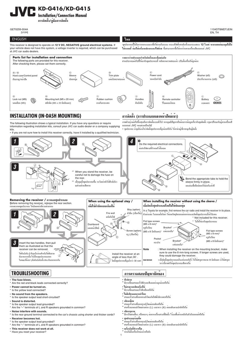
1.Solder is put up before the card wire is removed from connector on
the MD/CD substrate as shown in Figure.
(When the wire is removed without putting up solder, the pick-up
assembly might destroy.)
2.Please remove solder after connecting the card wire with
when you install picking up in the substrate.
*Please refer to "Disassembly method" in the text for pick-up and how to
detach the substrate.
SOLDER
POINT
SOLDER
POINT
Disassembly method
Removing the front panel assembly (see Fig. 1)
1. Press the release button on the right side of the
front panel, then press the front panel assembly
from the right side.
1.
2.
3.
4.
5.
6.
Removing the front panel assembly.
Removing the two screws A attaching the front
chassis.
Removing the one screw B attaching the right side
of front chassis.
Removing the one screw C attaching the left side
of front chassis.
Release two joint a fixing the front chassis.
Release the front chassis from the body.
Removing the front chassis (see Fig. 2~4)
Release button
Front panel assembly
Fig.1
Fig.2
Fig.3
Fig.4
A
B
a
a
C

Removing the bottom cover (see Fig. 5~7)
1.
2.
3.
4.
5.
Remove the front panel assembly.
Remove the front chasssis.
Turn the body up side down, then remove the two
screws Dattaching the bottom cove.
Release two joint bfixing the bottom cover on the
left and right side of the body.
Release the bottom cover from the body.
1.
2.
3.
4.
5.
6.
7.
Removing the front panel assembly.
Removing the front panel chassis.
Removing the bottom cover.
Removing the one screw Eattaching the top
chassis.
Removing the two screws Fattaching the side
bracket.
Removing the three screws Gattaching the main
board.
Removing the three screws H attaching the top
chassis.
Removing the main board (see Fig. 6~9) Fig.5 D
E
FF
b
b
Fig.6
Fig.7
Fig.8
G
G
HH
Fig.9

Removing the MD/CD mechanism (see Fig. 10~12)
1.
2.
3.
4.
5.
6.
7.
8.
Remove the front panel assembly.
Remove the front chasssis.
Removing the bottom cover.
Removing the main board.
Removing the two screws Iattaching the
mechanism.
From the left side of the body, remove the one
screw Jattaching the maechanism.
From the top of the body, remove the two screws
Kattaching the mechanism.
Removing the mechanism.
Fig.10
Fig.11
Fig.12
I
J
I
MD servo board
MD/CD
mechanism
K

Removing the operation switch board (see Fig. 13~14)
1.
2.
Remove the five screws Lattaching the front
cover.
Remove the control switch board from the front
panel unit.
Fig.13
Fig.14
L
L
Operation switch board
Front cover

Removing the MD servo board(see Fig.1,2)
Solder to flexible wire connect to CN301 from
mechanism.
(CAUTION)
Solder the pattern follow Fig.2.
When unsolder the pattern, easy to broken the
pickup at remove the flexible wire.
Remove the card wire and flexible wire connect to
CN502, CN503 and CN501.
Remove five screws Aattaching the MD servo
board.
1.
2.
3.
Removing the top cover assembly
(see Fig.3)
Remove the four screws B attaching the top cover
assembly.
To reassemble the top cover assembly, confirm
that the tab of the assembly is inserted into the
slot of the suspension flame unit (joint a) (see
"Reassembling main blocks.).
1.
<Disassembly method of MD/CD mechanism>
Fig.1
MD servo board Flexible wire
Suspension
flame Flexible wire
Fig.3
Top cover ass'y
Top cover Ass'y
Suspension
flame unit
Connect to
CN503
Card wire
A
A
A
A
A
BB
BB
a
Soldering
Fig.2
CN301
Flexible wire
Dissolder and
flat to the
bracket

FLOATING UNIT
DAMPER(RED)
DAMPER(BLUE) SUSPENSION FLAME ASS'Y
DAMPER(RED)
Fig.4
FLOATING UNIT SHAFT b
DAMPER(BLUE)
SUSPENSION
FLAME ASS'Y DAMPER(RED)
GEAR F.A.MOTOR SA
SHAFT b FLOATING UNIT
SUSPENSION FLAME ASS'Y
DAMPER(RED)
Fig.5
BLUE RED
DAMPER DAMPER
Fig.7
DAMPER
Fig.6
1.
2.
3.
4.
Remove the eight springs on the side of the body.
Since the springs are each different, treat them
carefully.
Turn the gear of the F.A.motor SA counterclockwise
to raise the Floating unit.Then, Shaft b is released.
Remove the three dampers. (One blue damper in
the rear of the unit, two red dampers on the left side
and the back side). Pull the tab of the damper to
release the joint as shown in the Fig.6.
NOTE-This mechanism has two kinds of damper.
So handle with care.
Remove the Floating unit upward from the
Suspension flame assembly.
Removing the Floating Unit (see Fig.4-7)

Removing the clamper assembly
(see Fig.8~10)
Loosen the one screw Cattaching the CL BASE
BKT. assembly.
Remove the clamp spring attached to the clamper
SA.
Push the CL. base BKT. assembly outward and
detach the clamper SA. in the direction of the
arrow.
1.
2.
3.
Removing the pickup unit
(Tra. mecha. SA) (see Fig.11~13)
Remove the two screws D attaching the ACT
motor SA.
Disengage the drive wheel from the worm wheel
of the Act. motor SA.
1.
Fig.8
Clamper base
bracket SA
Clamper base bracket SA
Fig.9 Fig.10
Clamper SA
Clamper SA
Clamper SA
Clamper spring
Clamper spring
Fig.11
Act. motor SA
Drive wheel
D
C
C

Turn the Drive wheel counterclockwise to move
the Pickup unit to the CD.position side.
After positioning the Pickup unit as shown in the
Fig.12,remove the E ring attaching the Pickup
unit. Then,lift the Media holder SA somewhat and
detach the Pickup unit by drawing it from the
shaft.
Solder the flexible harness connected to
connector CN321 in the rear of the Pickup unit
and disconnect the flexible harness connected to
connector CN311.Then remove the Pickup unit.
CAUTION- Make sure to solder the Flexible
harness before disconnecting to
prevent damage to the Pickup unit.
2.
3.
Reassembling the Pickup Unit
Fit the Pickup unit to the shaft at the position as
shown in Fig.12 and attach the E ring. At this
time, make sure that the shaft of the Swing arm
assembly is inserted into slot c of the Cam plate
assembly.
Lift the Media holder SA a little, and move the
Pickup unit to the MD position side by turning the
Drive wheel clockwise.
Removing the Suspension Flame Unit
Turn F.A.motor SA gear counterclockwise until it
stops,and allow the groove e of the Slide cam to
move to the left.
Remove the two screws E attaching F.A.motor
SA. Then move the F.A.motor SA in the direction
of the arrow to release joint d and remove it.
Remove each slider.
1.
2.
3. The sliders on the Suspension flame unit
can not be removed until F.A.motor SA is
removed.
After attaching the F.A.motor SA,turn the
Worm wheel counterclockwise to lift the
Suspension flame unit. Then,arrange and
position each slider.Make sure that each
slider works correctly after attaching.
NOTE1-
NOTE2-
Fig.12
MEDIA HOLDER SA
Fig.13
CN311
CN321
SUSPENSION FLAME UNIT
Fig.14
Fig.15
(See Fig.14 and 15)
SLIDE CAM
F.A.MOTOR SA
SWING ARM
Ass'y
CAM PLATE Ass'y
SLOTc
DRIVE WHEEL
E RING PICKUP UNIT
SOLDERING
FLEXIBLE HARNESS
SUSPENSION FLAME UNIT
E
E
e
d

Removing the L.Roller SA
Push parts f and g outside to release h, then
remove L.roller SA.
Remove Reverse springs (R) and (L) from the
Base chassis.
1.
2.
Removing the Media Holder SA
Remove the damper and two screws F attaching
the Media holder SA. Then,remove the Media
holder SA.
1.
To attach Media guide BKT., insert the bosses on
the Media holder and the arm into the slots of the
Media guide BKT.(see Fig.20)
To attach the Media holder SA., fit part J under
the Base chassis in advance.(see Fig.21).
Fig.16
Fig.18Fig.17
Fig.19
(see Fig.16 - 18) L.ROLLER SA
L.ROLLER SA
BASE CHASSIS
REVERSE SPRING(R) REVERSE SPRING(L)
(see Fig.19 - 21)
Reassembling the Media Holder SA
MEDIA HOLDER SA DAMPER
fg
hh
F
F

Removing the Up.Med.Guide(R)and
Switch Board
Remove the three screws G attaching the
Up.med.guide(R).
Remove the Switch board from the Top cover.
1.
2.
< Removal of parts forTop Cover Ass'y >
Reassembling theTop Cover Ass'y
To attach the Switch board, set the two holes of
the Switch board to the positioning holes of the
Top cover base. Do not fit each switch on the
lever.
Join three joints k, l and m. Then, fix the
Up.med.guide(R)by tightening the three screws G.
Removing the Up.Med.Guide(F)and
Shutter Ass'y
Remove the three screws H attaching the
Up.med.guide(F).
Remove the Shutter openers (R) and (L), Joint
gear and Shutter assembly from the Top cover
base.
1.
2.
Reassembling the UP.Med.Guide (F)and Shutter Ass'y
Attach the Shutter openers (R) and (L), Joint gear
and Shutter assembly to the Top cover base.(see
Fig.23)
Move each Shutter opener outward(in the
direction of the arrow) to return the Shutter
assembly to the initial position.
Insert both ends of the Up.med.guide (F) into the
notch of the Top cover base (First,attach part n.
Next, shift the Up.med.guide(F)to the right and
attach part p).
Tighten the two screws H to fix the
Up.med.guide(F)
1.
2.
Fig.20
Fig.21
Fig.22
Fig.23
Fig.24
(see Fig.22 and Fig.23)
(see Fig.22 - 24)
Fit the boss to the position
marked by the arrow.
UP.MED.GUIDE(F)
SHUT.OPENER(R) SHUTTER Ass'y SHUT.OPENER(L)
TOP COVER BASE SWITCH BOARD
UP.MED.GUIDE(F)
UP.MED.GUIDE(R) TOP COVER Ass'y
BASE CHASSIS
MEDIA HOLDER SA
M.GUIDE BKT
MEDIA HOLDER
j
FF
m
G
p
H
H
G
H
n
Gkl
SCREW
JOINT
GEAR

Removing the CD Roller
Remove the one Slit washer attaching CD shaft
SA.
Push part p of the CD load arm assembly outside
and remove the CD shaft SA.
Remove the Bush roller, two CD rollers, Center
guide and three washers from the CD shaft SA.
Then,remove the CD shaft SA from the CD load
arm assembly.
NOTE-When attaching the CD Roller, be sure to
attach the washers in the three positions
between the two CD rollers and Center
guide,and between the CD roller and CD
load arm assembly.
1.
2.
3.
< Removal of parts for L.Roller SA >
Removing the MD.Roller
Remove the one Slit washer attaching the MD
shaft SA.
Remove the Stopper, MD roller and Washer from
the MD shaft SA.
Remove the MD shaft SA. from the MD load arm
assembly.
1.
2.
Fig.25
Fig.26
(see Fig.25)
(see Fig.26)
CD SHAFT SA
CD LOAD ARM Ass'y
SLIT WASHER
WASHER
CD ROLLER
WASHER
CENTER GUIDE
WASHER
CD ROLLER
BUSH ROLLER
MD SHAFT SA
MD LOAD
ARM Ass'y
STOPPER
SLIT WASHER
MD ROLLER
WASHER
p

1.
2.
3.
4.
Remove the two screws I attaching the FPC.holder
and MC 2 mechanism board, and remove the FPC
holder.
Solder the Flexible harness connected to connector
CN321 as shown in the FIg.27.
CAUTION-Make sure to solder the Flexible harness
before disconnecting to prevent damage to
the Pickup unit.
Tear the adhesive tape fixing the harness outgoing
from the Spindle motor.
Shift the MC2 mechanism board in the direction of
the arrow and remove it from the Tra.mecha chassis
Ass'y.
FPC HOLDER TRA.MECHA.
CHASSIS Ass'y
SOLDERING
MC 2 MECHANISM BOARD
ADHESIVE TAPE
Fig.27
S.SHAFT SPRING
PICKUP UNIT
FEED MOTOR SA
SWING SPRING
CAM PLATE Ass'y
Fig.28
RACK
SPRING
PICKUP UNIT
THRUST SPRING
S.SHAFT SA
Fig.29
< Removal of parts for theTra.Mecha.SA >
Removing the MC 2 Mechanism Board
(see Fig.27)
Removing the Pickup unit (see Fig.28 and 29)
1.
2.
3.
4.
5.
6.
7.
Remove the Swing spring and Cam plate assembly.
Remove the one screw J and detach the S.shaft spring.
Remove the Feed motor SA.
Remove the Pickup unit from the Pickup base.(At this time,
move the Pickup SA.to the CD side)
Remove the one screw K and detach the Thrust spring.
Remove the two screws L and detach the Rack spring.
Turn the S.shaft SA.in the direction of the arrow and draw it
from the Pickup unit.
Only the aluminous die-casting of the
Pickup unit should be touched.
The Pickup lens must be protected
against damage.
Do not unsolder the Pickup wire until all
wiring of the MD servo board is
completed.
1.
2.
3.
CAUTIONS-

Attach the S.shaft SA., Rack spring and Thrust
spring to the Pickup unit.
Fit parts r and s of the Feed motor SA.under the
Tra.mecha chassis Ass'y, and attach the Feed
motor SA. to the Tra.mecha. chassis.
NOTE-If the Rest SW.ACT has been removed,
attach if before attaching the Feed motor
SA.To attach the Rest SW. ACT, insert
tab t into the slot of the Tra.mecha.chassis
Ass'y(see Fig.30)
Attach the S.shaft spring by setting the two holes
to the bosses on the Tra.mecha.chassis assembly.
Tighten the screw J.
Attach the Cam plate assembly and Swing spring.
Make sure to attach the Swing spring and its both
ends as shown in the Fig.31.
Attach the FPC holder to the MC 2 mechanism
board by tightening the two screws I.
Tape the harness outgoing from the Spindle
motor. Make sure that the harness is not loose.
1.
2.
3.
4.
5.
6.
Fig.30
Fig.31
Fig.28
Fig.27
Fig.29
Reassembling theTra.Mecha.SA
(see Fig.27 - 31)
RACK SPRING
PICKUP UNIT
THRUST SPRING
S.SHAFT SA
REST SW.ACT
PICKUP UNIT
TRA.MECHA.
CHASSIS Ass'y
CAM PLATE Ass'y
FEED MOTOR SA
CAM PLATE Ass'y
SWING SPRING
PICKUP UNIT
FEED MOTOR SA
S.SHAFT SPRING
SWING SPRING CAM PLATE Ass'y
FPC HOLDER TRA.MECHA.
CHASSIS Ass'y
SOLDERING
MC 2 MECHANISM BOARD ADHESIVE TAPE
L
K
II
t
s
r
J
CN321

Removing the Load Board
Disconnect the harnesses connected to
connector CN521 and CN522, and flexible
harness connected to CN511.
Remove the screw M attaching the Load board.
1.
2.
< Removal of parts for Chassis >
Removing the Load Motor SA
Remove the two screws N attaching the Load
motor SA.
1.
Fig.32
Fig.33
(see Fig.32)
(see Fig.33)
FLEXIBLE
HARNESS
CN521
CN511
LOAD BOARD
M
CN522
M
N
NLOAD MOTOR SA

Reassembling Main Assemblies
Reassemble the Pickup unit(see "Reassembling
the Tra.Mecha SA")
Attach the Pickup unit to the Pickup base
(see "Removing the Pickup Unit")
Attach the Media holder SA.(see "Removing the
Media Holder SA.")
Attach the L.roller SA.(see "Removing the L.Roller
SA")
Attach the Clamper SA and fix the CL.base
BKT.Ass'y.(see "Removing the Clamper SA")
Attach the Floating unit to the Suspension flame
unit.(see "Removing the Floating Unit")
NOTE 1:Attach each slider of the Suspension
flame unit before attaching the FA.motor
SA.(Each slider can not be detached or
attached after the F.A.motor SA is
attached.)
NOTE 2:The dampers and springs used in the
Floating unit are each different,so attach
them to the correct positions.
NOTE 3:Attach the Floating unit to the lifted
Suspension flame.Then,attach the
damper.Turn the F.A.motor SA clockwise
as shown in the Fig.14 and 34.Then both
ends of the shaft is locked.
(see Fig.34 and 14)
NOTE4 :After attaching the Floating unit, confirm
that parts u and v in the back of the body
are as shown in the Fig.35.
Attach the Top cover Ass'y
(see "Removing the Top Cover Ass'y")
NOTE 1:Before attaching theTop cover, lock the
Floating unit and return the Top cover
Ass'y to the initial position.
NOTE 2:To attach the Top cover, insert tab y' of
the Top cover Ass'y into slotY of the
Suspension flame.
Attach the MD servo board.
(see "Removing the MD servo board")
Make sure that each harness is attached to the
connector correctly.
1.
2.
3.
4.
5.
6.
7.
8.
Refer to each item for removal.
Fig.34
Fig.35
Fig.36
FLOATING UNIT SHAFT
GEAR F.A.MOTOR SA
u
v
TOP COVER Ass'y
y'
Y

This is the easiest method to remove the Pickup unit.
Solder the flexible harness connected to
connector CN301 on the MD servo board,and
remove it.
Disconnect the harness, card wire and flexible
harness connected to connector CN502, CN503
and CN501 respectively.
CAUTION-Make sure to solder the flexible
harness before disconnecting to
prevent damage to the Pickup unit.
Remove the four screws B attaching the Top cover
assembly.
1.
2.
< Removal of the Pickup unit >
Removing theTop Cover Ass'y
Loosen the two screws D attaching the CL.base
BKT. Ass'y.
Remove the Clamp spring attached to the
Clamper SA.
Push the CL.base BKT.assembly outside and
remove the Clamper SA upward as shown in the
Fig.37.
1.
2.
3.
Removing the Clamper SA
Remove the two screws C attaching the
ACT.motor SA.Disengage the Drive wheel from
the Worm wheel of the Act.motor SA.
Turn the Drive wheel counterclockwise to move
the Pickup unit to the CD position side. After
moving the Pickup unit as shown in the Fig.12,
remove the E ring attaching the Pickup unit.Then,
lift the Media holder SA.somewhat, detach the
Pickup unit with drawing it from the shaft.
After soldering the Flexible harness connected to
connector CN321 in the rear of the Pickup unit,
disconnect the Flexible harness connected to
connector CN311.Then remove the Pickup unit.
1.
2.
3.
3Removing the Pickup Unit
Fig.37
Fig.38
Fig.39
1(see Fig.1-3)
2(see Fig.37,and 8-10)
(see Fig.38,39 and 11-13)
CLAMPER SA
CL.BASE.BKT.Ass'y
CLAMP SPRING
DRIVE
WHEEL
ACT.MOTOR SA
D
MEDIA HOLDER SA
PICKUP UNIT
E RING
DRIVE WHEEL
CAM PLATE Ass'y
GROOVE c
SWING ARM Ass'y
C

Adjustment method
PRESET MODE
1. Descriptions
3. Details
2. Order
Adjustment should start at laser adjustment.
1. Laser power adjustment UP/DOWN by manual adjustment at F.SKIP/B.SKIP
2. EF balance adjustment & TROFFSET Automatic
3. IVR & Servo gain Automatic
4. Jitter confirmation Jitter readjust by UP/DOWN at manual adjustment for
F.SKIP/B.SKIP when jitter out of spec.
These items memory to EEPROM.Then use at normal playback.
(1) Preset mode (Press SEL+CD-CH+I/O att key more than 2 second)
(2) Insert the MD cartridge type laser power sensor. "SEL ADJ" indication
(3) Press 2 key Laser adjustment by F.SKIP/B.SKIP. "LASER ADJ 59" indication
(4) Press EJECT key to remove the sensor. "LASER END" "Preset Mode" indication
(5) Insert CTS-1000 "SEL ADJ" indication
(6) Press 1 key EF balance adjustment automatically. "CD ADJ" indication
(7) Check jitter. "CD1 FBIAS 00" indication
(8) Eject Memory to EEPROM . "CD OK" "Preset Mode" indication
(9) Insert TGYS1. "SEL ADJ" indication
(10) Press 1 key EF balance adjustment automatically. "Pre pitMD ADJ" indication
(11) Check jitter. "Pit FBIAS 00" indication
(12) Eject Memory to EEPROM. "Pre pitMD ADJ" "Preset Mode" indication
(13) Insert AU1. "SEL ADJ" indication
(14) Press 1 key EF balance adjustment automatically. "MO PIT ADJ" indication
(15) Check jitter. "MOP FBIAS 00" indication
(16) Press 1 key EF balanse adjustment automatically. "MO PIT OK" "MO GrooveADJ" indication
(17) Check jitter. "MOG FBIAS 00" indication
(18) Eject Memory to EEPROM. "MO OK" indication
(19) "PRESET END"
Complete If each disc adjustment NG indication is "ADJ NG"
(1) Switch to Preset Mode
"Select the SERVICE MODE"
Set to the PRESET MODE by press SEL+CD-CH+I/O att key more than 2 second
(2) Laser power adjustment
Adjust by MD cartridge type laser sensor (AIC-001).
Complete the adjustment, press EJECT key.
Test instruments
POWER METER
POWER METER
SENSOR
Model
TQ8215
TQ8210
AC-001
Maker
ADVANTEST
ADVANTEST
ADVANTEST
Adjustment
F.SKIP
B.SKIP
Specification
680 + 30 W
- 0 W
Other manuals for KD-MX2900R
1
Table of contents
Other JVC Car Receiver manuals
Popular Car Receiver manuals by other brands

Dual
Dual XDMR7700 Installation & owner's manual

Farenheit
Farenheit DVD-22T owner's manual

Pioneer
Pioneer DEH-P600UB - Premier Radio / CD quick start guide

Panasonic
Panasonic CQ-D1703N operating instructions

Pioneer
Pioneer DEH-P550MP installation manual

Boss Audio Systems
Boss Audio Systems 634U user manual

LG
LG LAC2900RNP manual

Dual Electronics Corporation
Dual Electronics Corporation DCPA901 Installation & owner's manual

ESX
ESX Vision Naviceiver VNS720 FI-DUCATO installation guide

Dual
Dual XDVDN8190 Installation & owner's manual

Rockford Fosgate
Rockford Fosgate RFX9700CD instruction manual
![Kenwood Z910DVD[K] instruction manual Kenwood Z910DVD[K] instruction manual](/data/manuals/2i/b/2ibzh/sources/kenwood-z910dvd-k-car-receiver-manual.jpg)
Kenwood
Kenwood Z910DVD[K] instruction manual