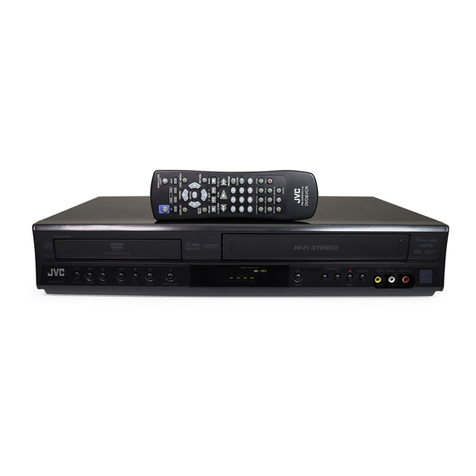
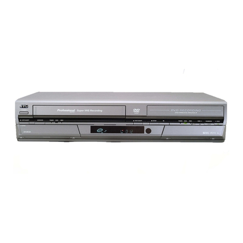
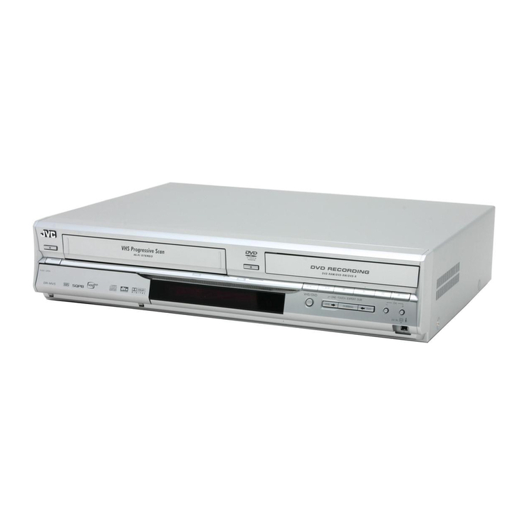
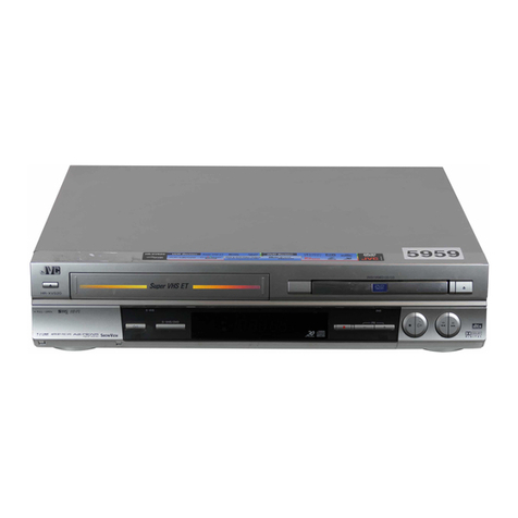
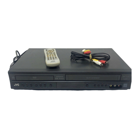
JVC HR-XV45SEF User manual

SERVICE MANUAL
COPYRIGHT © 2005 Victor Company of Japan, Limited No.YD070
2005/7
DVD PLAYER & VIDEO CASSETTE RECORDER
YD07020057
HR-XV45SEF, HR-XV45SEK,
HR-XV45SER, HR-XV45SEU,
HR-XV45SEY, HR-XV45SEZ
TABLE OF CONTENTS
1 PRECAUTION. . . . . . . . . . . . . . . . . . . . . . . . . . . . . . . . . . . . . . . . . . . . . . . . . . . . . . . . . . . . . . . . . . . . . . . . . 1-3
2 SPECIFIC SERVICE INSTRUCTIONS . . . . . . . . . . . . . . . . . . . . . . . . . . . . . . . . . . . . . . . . . . . . . . . . . . . . . . 1-6
3 DISASSEMBLY . . . . . . . . . . . . . . . . . . . . . . . . . . . . . . . . . . . . . . . . . . . . . . . . . . . . . . . . . . . . . . . . . . . . . . . 1-9
4 ADJUSTMENT . . . . . . . . . . . . . . . . . . . . . . . . . . . . . . . . . . . . . . . . . . . . . . . . . . . . . . . . . . . . . . . . . . . . . . . 1-10
5 TROUBLESHOOTING . . . . . . . . . . . . . . . . . . . . . . . . . . . . . . . . . . . . . . . . . . . . . . . . . . . . . . . . . . . . . . . . . 1-37
HR-XV45SEF,HR-XV45SEK,HR-XV45SER,HR-XV45SEU,HR-XV45SEY,HR-XV45SEZ [D5PV1]
(EK model)
(EF model)
(EU, EY, EZ models)
(EF, ER models)

1-2 (No.YD070)
SPECIFICATION
• Designs and specifications are subject to change without notice.
• Manufactured under license from Dolby Laboratories. "Dolby", "Pro Logic" and the double-D symbol are trademarks of Dolby Lab-
oratories.
• DTS and DTS Digital Out are trademarks of Digital Theater Systems, Inc.
• SHOWVIEW is a trademark of Gemstar Development Corporation. The SHOWVIEW system is manufactured under license from
Gemstar Development Corporation.(EF/ER/EU/EY/EZ models)
• VIDEO Plus+ and PlusCode are registered trademarks of Gemstar Development Corporation. The VIDEO Plus+ system is man-
ufactured under license from Gemstar Development Corporation.(EK model)
HR-XV45SEF HR-XV45SEK HR-XV45SER/SEU/SEY/SEZ
General
Power requirement AC 200V - 240V, 50 Hz
Power consumption 17 W
Dimensions (approx.) 430 ×78.5 ×265 mm (w/h/d)
Mass (approx.) 4.2 kg
Operating temperature 5°C to 35°C (41°F to 95°F)
Operating humidity 5 % to 90 %
Timer 24 hours display type
RF Modulator - UHF 22-68 (Adjustable)
System
Laser Semiconductor laser, wavelength 650 nm
Video Head system Double azimuth 6 heads, helical scanning.
Signal system PAL
Frequency response DVD (PCM 96 kHz): 8 Hz to 44 kHz, DVD (PCM 48 kHz): 8 Hz to 22 kHz, CD: 8 Hz to 20 kHz
Signal-to-noise ratio More than 100 dB (ANALOG OUT connectors only)
Harmonic distortion Less than 0.008%
Dynamic range More than 100 dB (DVD), More than 95 dB (CD)
Inputs (VCR)
Audio -6.0 dBm, more than 10 kΩ(SCART), -6.0 dBm, more than 47 kΩ(RCA)
Video 1.0 V (p-p), 75 Ω, unbalanced (SCART/RCA)
Outputs (DVD)
VIDEO OUT 1 Vp-p 75 Ω, sync negative
Audio output (digital audio) 0.5 V (p-p), 75 Ω, RCA jack ×1
Audio output (analog audio) 2.0 Vrms (1 kHz, 0 dB), 600 Ω, RCA jack (L, R) x 1/SCART (TO TV)
Outputs (VCR)
Audio -6.0 dBm, less than 1 kΩ(SCART)
Video 1.0 V (p-p), 75 Ω, unbalanced (SCART)

(No.YD070)1-3
SECTION 1
PRECAUTION
1.1 SAFTY PRECAUTIONS
Prior to shipment from the factory, JVC products are strictly in-
spected to conform with the recognized product safety and elec-
trical codes of the countries in which they are to be
sold.However,in order to maintain such compliance, it is equally
important to implement the following precautions when a set is
being serviced.
1.1.1 Precautions during Servicing
(1) Locations requiring special caution are denoted by labels
and inscriptions on the cabinet, chassis and certain parts of
the product.When performing service, be sure to read and
comply with these and other cautionary notices appearing
in the operation and service manuals.
(2) Parts identified by the symbol and shaded ( ) parts
are critical for safety.
Replace only with specified part numbers.
NOTE :
Parts in this category also include those specified to
comply with X-ray emission standards for products
using cathode ray tubes and those specified for
compliance with various regulations regarding spu-
rious radiation emission.
(3) Fuse replacement caution notice.
Caution for continued protection against fire hazard.
Replace only with same type and rated fuse(s) as speci-
fied.
(4) Use specified internal wiring. Note especially:
• Wires covered with PVC tubing
• Double insulated wires
• High voltage leads
(5) Use specified insulating materials for hazardous live parts.
Note especially:
• Insulation Tape
• PVC tubing
•Spacers
• Insulation sheets for transistors
•Barrier
(6) When replacing AC primary side components (transformers,
power cords, noise blocking capacitors, etc.) wrap ends of
wires securely about the terminals before soldering.
Fig.1-1-1
(7) Observe that wires do not contact heat producing parts
(heatsinks, oxide metal film resistors, fusible resistors, etc.)
(8) Check that replaced wires do not contact sharp edged or
pointed parts.
(9) When a power cord has been replaced, check that 10-15
kg of force in any direction will not loosen it.
Fig.1-1-2
(10) Also check areas surrounding repaired locations.
(11) Products using cathode ray tubes (CRTs)In regard to such
products, the cathode ray tubes themselves, the high volt-
age circuits, and related circuits are specified for compli-
ance with recognized codes pertaining to X-ray emission.
Consequently, when servicing these products, replace the
cathode ray tubes and other parts with only the specified
parts. Under no circumstances attempt to modify these cir-
cuits.Unauthorized modification can increase the high volt-
age value and cause X-ray emission from the cathode ray
tube.
(12) Crimp type wire connectorIn such cases as when replacing
the power transformer in sets where the connections be-
tween the power cord and power trans former primary lead
wires are performed using crimp type connectors, if replac-
ing the connectors is unavoidable, in order to prevent safe-
ty hazards, perform carefully and precisely according to the
following steps.
•Connector part number :E03830-001
•Required tool : Connector crimping tool of the proper
type which will not damage insulated parts.
•Replacement procedure
a) Remove the old connector by cutting the wires at a
point close to the connector.Important : Do not re-
use a connector (discard it).
Fig.1-1-3
b) Strip about 15 mm of the insulation from the ends
of the wires. If the wires are stranded, twist the
strands to avoid frayed conductors.
Fig.1-1-4
c) Align the lengths of the wires to be connected. In-
sert the wires fully into the connector.
Fig.1-1-5
d) As shown in Fig.1-1-6, use the crimping tool to
crimp the metal sleeve at the center position. Be
sure to crimp fully to the complete closure of the
tool.
Fig.1-1-6
e) Check the four points noted in Fig.1-1-7.
Fig.1-1-7
Power cord
cut close to connector
15 mm
Connector
Metal sleeve
1.25
2.0
5.5
Crimping tool
Not easily pulled free Crimped at approx. cente
r
of metal sleeve
Conductors extended
Wire insulation recessed
more than 4 mm
1-4 (No.YD070)
1.1.2 Safety Check after Servicing
Examine the area surrounding the repaired location for damage
or deterioration. Observe that screws, parts and wires have been
returned to original positions, Afterwards, perform the following
tests and confirm the specified values in order to verify compli-
ance with safety standards.
(1) Insulation resistance test
Confirm the specified insulation resistance or greater be-
tween power cord plug prongs and externally exposed
parts of the set (RF terminals, antenna terminals, video and
audio input and output terminals, microphone jacks, ear-
phone jacks, etc.).See table 1 below.
(2) Dielectric strength test
Confirm specified dielectric strength or greater between
power cord plug prongs and exposed accessible parts of
the set (RF terminals, antenna terminals, video and audio
input and output terminals, microphone jacks, earphone
jacks, etc.). See Fig.1-1-11 below.
(3) Clearance distance
When replacing primary circuit components, confirm spec-
ified clearance distance (d), (d') between soldered termi-
nals, and between terminals and surrounding metallic
parts. See Fig.1-1-11 below.
Fig.1-1-8
(4) Leakage current test
Confirm specified or lower leakage current between earth
ground/power cord plug prongs and externally exposed ac-
cessible parts (RF terminals, antenna terminals, video and
audio input and output terminals, microphone jacks, ear-
phone jacks, etc.).
Measuring Method : (Power ON)Insert load Z between
earth ground/power cord plug prongs and externally ex-
posed accessible parts. Use an AC voltmeter to measure
across both terminals of load Z. See Fig.1-1-9 and follow-
ing Fig.1-1-12.
Fig.1-1-9
(5) Grounding (Class 1 model only)
Confirm specified or lower grounding impedance between
earth pin in AC inlet and externally exposed accessible
parts (Video in, Video out, Audio in, Audio out or Fixing
screw etc.).Measuring Method:
Connect milli ohm meter between earth pin in AC inlet and
exposed accessible parts. See Fig.1-1-10 and grounding
specifications.
Fig.1-1-10
Fig.1-1-11
Fig.1-1-12
NOTE :
These tables are unofficial and for reference only. Be sure to confirm the precise values for your particular country and locality.
Chassis
Power cord
primary wire
d'
d
ab
c
V
A
Externally
exposed
accessible part
Z
Exposed accessible part
Grounding Specifications
AC inlet
Region
USA & Canada
Europe & Australia
Grounding Impedance (Z)
Z 0.1 ohm
Z 0.5 ohm
Earth pin
MIlli ohm meter
AC Line Voltage Region
Japan
Europe & Australia
R 1 M /500 V DC
USA & Canada 1 M R 12 M /500 V DC
R 10 M /500 V DC
Insulation Resistance (R)Dielectric Strength Clearance Distance (d), (d')
100 V
100 to 240 V
110 to 130 V
110 to 130 V
200 to 240 V
AC 1 kV 1 minute
AC 1.5 kV 1 minute
AC 1 kV 1 minute
(Class )
(Class )
AC 3 kV 1 minute
AC 1.5 kV 1 minute
d, d' 3 mm
d, d' 4 mm
d, d' 3.2 mm
d' 8 m m (Power cord)
d' 6 m m (Primary wire)
d 4 m m
AC Line Voltage Region
Japan
Europe & Australia
USA & Canada
Load Z Leakage Current (i) a, b, c
100 V
110 to 130 V
110 to 130 V
220 to 240 V
i 1 mA rms
i 0.5 mA rms
i 0.7 mA peak
i 2 mA dc
i 0.7 mA peak
i 2 mA dc
Exposed accessible parts
Antenna earth terminals
Other terminals
1
1.5
2
50
0.15

(No.YD070)1-5
1.2 Preventing static electricity
Electrostatic discharge (ESD), which occurs when static electricity stored in the body, fabric, etc. is discharged, can destroy the laser
diode in the traverse unit (optical pickup). Take care to prevent this when performing repairs.
1.2.1 Grounding to prevent damage by static electricity
Static electricity in the work area can destroy the optical pickup (laser diode) in devices such as DVD players.
Be careful to use proper grounding in the area where repairs are being performed.
(1) Ground the workbench
Ground the workbench by laying conductive material (such as a conductive sheet) or an iron plate over it before placing the
traverse unit (optical pickup) on it.
(2) Ground yourself
Use an anti-static wrist strap to release any static electricity built up in your body.
(3) Handling the optical pickup
• In order to maintain quality during transport and before installation, both sides of the laser diode on the replacement optical
pickup are shorted. After replacement, return the shorted parts to their original condition.
(Refer to the text.)
• Do not use a tester to check the condition of the laser diode in the optical pickup. The tester's internal power source can easily
destroy the laser diode.

1-6 (No.YD070)
SECTION 2
SPECIFIC SERVICE INSTRUCTIONS
2.1 DIFFERENT TABLE OF FEATURE
The following table indicates main different points between models HR-XV45SEF, HR-XV45SEK, HR-XV45SER, HR-XV45SEU and
HR-XV45SEY/EZ.
Note:
Mark ←is same as left.
MODEL NAME HR-XV45SEF HR-XV45SEK HR-XV45SER
SCART CABLE PROVIDED ←OPTIONAL
BROADCASTING SYSTEM PAL B/G, SECAM L PAL I, I/I, B/G, SECAM D/K, K1 ←
RF OUT CH/RF OUT
SYSTEM [INITIAL] NOT USED 22-68CH,[36CH]/I 22-68CH,[36CH]/K
OSD LANGUAGES ENGLISH/GERMANY/FRENCH/
ITALIAN/SPANISH/DUTCH
ENGLISH/GERMANY/ITALIAN/
SPANISH/GREEK/PORTU-
GUESE
ENGLISH/RUSSIAN
REGIONAL CODE REGIONAL CODE : 2 ←REGIONAL CODE : 5
MODEL NAME HR-XV45SEU HR-XV45SEY/EZ
SCART CABLE OPTIONAL ←
BROADCASTING SYSTEM PAL I, I/I, B/G, SECAM D/K, K1 ←
RF OUT CH/RF OUT
SYSTEM [INITIAL] 22-68CH,[36CH]/G ←
OSD LANGUAGES
ENGLISH/GERMANY/ITALIAN/
SPANISH/GREEK/PORTU-
GUESE
ENGLISH/POLISH/CZECH/
HUNGARIAN/SWEDISH/GER-
MANY
REGIONAL CODE REGIONAL CODE : 2 ←

(No.YD070)1-7
2.2 SERVICE INFORMATION FOR EEPROM IC SETTING(VCR)
EEPROM option code No. setting EEPROM option code No. setting procedure
NAME HEX BINARY
OPT0 00 00000000
OPT1 00 00000000
OPT2 00 00000000
OPT3 00 00000000
OPT4 00 00000000
OPT5 00 00000000
12/26 - 00 V00 -COM Ver.
ID : LG
VERSION : 05 ROM
DATE : 02.17.05 Correction Ver.
1. DETECT NEW EEPROM (OPTION EDIT
SCREEN)
- Eeprom EDIT screen automatically appears if
replacing Eeprom.
- Setup option data using the cursor Up/Down key
of a remote control.
(Setup upon BOM depending on OPT0~OPT5
model)
Since an initial remote control is set to LG for LG
model, appropriately set optiona data using the
cursor Up/Down key.
2. EEPROM WRITED AND EEPROM INITIAL
- Writes data on EEPROM by using REMOCON
"OK" + FRONT PLAY KEY FOR MORE THAN 5
SECONDS.
3. PG ADJUST
1) Payback the SP standard tape
2) Press the "OK" key on the Remote controller
and the "PLAY" key on the Front Panel the
same time, then it goes in to Tracking initial
mode.
3) Repeat the above step(No.2), then it finishes
the PG adjusting automatically.
4) Stop the playback, then it goes out to PG
adjusting mode after mony the PG data.
4. BUYER SELECTION
- Font ejection key + open/close key for more than
5 seconds.
- Option code is displayed in TV
- First byte of OPTO is changed whenever front
eject key + open/close key.
- JVC remote conroller No.0.
MODEL NAME HEX BINARY
HR-XV45SEU OPT0 00 00000000
OPT1 F4 00000000
OPT2 60 00000000
OPT3 47 00000000
OPT4 03 00000000
OPT5 4B 00000000
HR-XV45SEK OPT0 00 00000000
OPT1 F4 00000000
OPT2 21 00000000
OPT3 87 00000000
OPT4 0D 00000000
OPT5 4B 00000000
HR-XV45SEY OPT0 00 00000000
OPT1 F4 00000000
OPT2 60 00000000
OPT3 47 00000000
OPT4 0B 00000000
OPT5 4B 00000000
HR-XV45SEZ OPT0 00 00000000
OPT1 D4 00000000
OPT2 60 00000000
OPT3 47 00000000
OPT4 0D 00000000
OPT5 4B 00000000
HR-XV45SER OPT0 09 00000000
OPT1 54 00000000
OPT2 A3 00000000
OPT3 47 00000000
OPT4 0D 00000000
OPT5 4B 00000000
HR-XV45SEF OPT0 00 00000000
OPT1 FC 00000000
OPT2 E8 00000000
OPT3 47 00000000
OPT4 0D 00000000
OPT5 4B 00000000
WR : OK I : EXIT MOVE :
EDIT :

1-8 (No.YD070)
2.3 SERVICE INFORMATION FOR EEPROM (DVD)
POWER ON
DVD LOGO Status (NO Disk status)
Press pause key once
Change will be applied when power
OFF ON.
Remote control
Pause key 1 4 7 2 in order.
Press number 0~9, Press charater
A~F (1~6 for a while)
DETECT NEW EEPROM
(OPTION EDIT SCREEN)
Use arrow key ( ) to move
to approprite position and make
changes
MODEL
HR-XV45SEU HR-XV45SEK HR-XV45SEY HR-XV45SEZ HR-XV45SER HR-XV45SEF
NAME HEX HEX HEX HEX HEX HEX
OPT 1 44 47 53 50 52 42
OPT 2 45 42 45 4C 55 45
OPT 3 00 00 00 00 00 00
OPT 4 D3 D3 D3 D3 D3 D3
OPT 5 12 12 12 12 12 12
OPT 6 05 05 05 05 05 05
OPT 7 B0 B0 B0 B0 B0 B0
OPT 8 00 00 00 00 00 00
OPT 9 00 00 00 00 00 00
OPT A 00 00 00 00 00 00
OPT B 80 80 80 80 80 80
OPT C 00 00 00 00 0A 00
OPT D 00 00 00 00 00 00
OPT E 00 00 00 00 00 00
OPT F 00 00 00 00 00 00
OPT G 00 00 00 00 00 00
* OPTION
NTSC model does not have VCR option and use DVD option B~F as VCR option. (only DVD exist)
PAL model has another separate VCR option. (Both VCR and DVD exist)

(No.YD070)1-9
SECTION 3
DISASSEMBLY
This service manual does not describe DISASSEMBLY.

1-10 (No.YD070)
SECTION 4
ADJUSTMENT
4.1 POSITION DRAWING OF DECK MECHANISM PARTS (VCR)
5
4
3
2
6
9
10
8
12
18
16
19
17
13
15
11
1
33
14
7
15
35
21
21
24
23
22
31
32
31
32
25
34
28
27
29
20
26
30
24
Top View
Bottom View
NOTE : Assembly order is a reverse of
disassembly order.
(1) For assembly, check the assembly mode is accurate.
(2) Parts firstly disassembled indicate parts firstly disassembled
in disassembly of related parts.
T:Top, B:Bottom
Part
Order Of Dis-
assembled
Parts firstly
Disassembled
Fixing Type
Ref.
Draw-
ings
Posi
tion
1
2
3
4
5
6
7
8
9
10
11
12
13
14
15
16
17
18
19
20
21
22
23
24
25
26
27
28
29
30
31
32
33
34
35
A-1
A-2
A-2
A-2
A-2
A-2
A-2
A-3
A-3
A-3
A-3
A-3
A-4
A-4
A-4
A-5
A-5
A-5
A-5
A-6
A-6
A-6
A-6
A-7
A-7
A-7
A-7
A-7
A-7
A-7
A-8
A-8
A-8
A-9
A-9
T
T
T
T
T
T
T
T
T
T
T
T
T
T
T
T
T
T
T
B
B
B
B
B
B
B
B
B
B
B
B
B
B
T
T
2
2,3
2,3,4
2,3,4,5
2,3
2,3
2,3,13,14
17
17
17,18
21,22
21
21,22,23,
24,25,26
21,22,23,
24,25,26,27
21,22,23,
24,25,26,27
21,22,23,
24,25,26,27
25
2,3,14,
25,31
25,31
2,3,14
Drum Assembly
Plate Top
Holder Assembly CST
Gear Assembly Rack F/L
Opener Door
Arm Assembly F/L
Lever Assembly S/W
Motor Assembly L/D
Gear Wheel
Arm Assembly Cleaner
Head F/E
Base Assembly A/C Head
Brake Assembly T
Arm Assembly Tension
Reel S / Reel T
Base Assembly P4
Opener Lid
Arm Assembly Pinch
Arm T/up
Supporter, capstan
Belt Capstan/Motor Capstan
Lever F/R
Clutch Assembly D37
Gear Drive/Gear Cam
Gear Sector
Brake Assembly Capstan
Plate Slider
Lever Tension
Lever Spring
Lever Brake
Gear Assembly P2/
Gear Assembly P3
Base Assembly P2
/Base Assembly P3
Base Loading
Base Tension
Arm Assembly Idler Jog
3 screws
2 hooks
6 chasses
1 hook
Chassis Hole
Chassis Hole
Chassis Hole,
1 hook
1 screw
2 hooks
Chassis Embossing
Chassis Embossing
1 screw
1 hook
1 hook
Shaft
Chassis Embossing
Chassis Embossing
Shaft
1 hook
Chassis Hole
3 screws
Tab
Washer
Washer/Hook
Hook
Chassis Hole
Chassis Guide
1 Hook
1 Hook
1 Hook
Bass
6 Chasses
3 Hooks
Chassis Embossing
Locking Tab

(No.YD070)1-11
4.2 DISASSEMBLY AND ASSEMBLY OF DECK MECHANISM (VCR)
Cap, FPC
Drum Assembly
Cable Flat
(S1) (S1)
(S1)
Holder FPC
H1
H2
Holder FPC
Drum FPC
Cap FPC
Fig. A-1
Cautions in assembly of FPC
Assembly shape seen in the reverse direction
1. Disassembly of Drum Assembly
(Figure A-1)
1) Separate cable flat from the Drum FPC and the Capstan
Motor.
2) Release 3 screws (S1) on the bottom side of the chassis,
and separate the drum assembly.
3) Release the hooks (H1, H2) and separate both the holder
FPC and the Cap FPC (disassemble if necessary).

1-12 (No.YD070)
(B)
(E)
(C)
Plate Top
Arm Assembly F/L
Gear Assembly Rack F/L
Opener Door
Holder Assembly CST
(B')
(H3)
(A) (B)
Lever Assembly S/W
(H4)
(E)
(Fig. A-2-1)
(Fig. A-2-2)
(Fig. A-2-5)
(Fig. A-2-6)
(Fig. A-2-3)
(Fig. A-2-4)
Fig. A-2

(No.YD070)1-13
2. Disassembly of Plate Top (Fig. A-2-1)
1) Separate the right part while leaning back the (B) part of
the plate top toward the arrow direction.
2) Separate the left part while leaning back the (B f) part of
the plate top toward the arrow direction.
(Tool used: Tool such as (-) driver, auger, etc with pointed
or flat end)
3. Holder Assembly CST (Fig. A-2-2)
1) Firstly separate the left part from the groove on the (D)
part of chassis while moving the holder assembly CST
toward the arrow direction.
Assemble by inserting the left part after firstly inserting the
(E) part of the holder assembly CST into the groove on the
(E') part of chassis.
2) Separate the right part from each groove of chassis
5. Opener Door (Fig. A-2-4)
1) Separate the opener door ahead from the guide hole of
chassis while turning it clockwise.
7. Lever Assembly S/W (Fig. A-2-6)
1) Separate the lever assembly S/W while pushing it toward
the arrow direction after removing the hook (4) on the left
side of chassis.
6. Arm Assembly F/L (Fig. A-2-5)
1) Firstly separate the left part of the arm assembly F/L from
the groove of chassis while pushing the arm assembly F/L
toward the arrow direction.
2) Separate the right part from the groove of chassis.).
4. Disassembly of Gear Assembly
Rack F/L (Fig. A-2-3)
1) Separate the hook (H3) while leaning ahead the hook (3)
after moving the gear assembly rack F/L toward the arrow
(A) direction.
2) Separate the gear assembly rack F/L toward the arrow (B)
direction.
CAUTIONS
CAUTIONS
CAUTIONS
(B')
(C')
(C)
(B)
(D)
Holder Assembly CST Chassis
Chassis
Gear Rack F/L
Gear Drive
Assemble while pressing the (C), (C') part after correspond-
ing them as in drawing.
For the assembly, correspond the gear part of gear assembly
rack F/L to the gear drive.
(H4)

1-14 (No.YD070)
Arm Assembly Cleaner
Motor Assembly L/D
Gear Wheel
Base Assembly A/C Head
(S4)
(S5)
Head F/E
(A)
(C1)
(H5)
(A)
Fig. A-3
(Fig. A-3-3)
(Fig. A-3-5)
(Fig. A-3-4)
(Fig. A-3-2)
(Fig. A-3-1)
8. Motor Assembly L/D (Fig. A-3-1)
1) Take the connector (C1) connected to the Capstan motor
PCB out.
2) Remove a screw (S4) of the chassis (S4) and step back-
ward, and disassemble it while holding it up.
9. Gear Wheel (Fig. A-3-2)
1) Release the hook (H5) of the gear wheel and disassemble
it upward.
10. Arm Assembly Cleaner (Fig. A-3-3)
1) Separate the (A) part of Fig. A-3-1 from the embossing of
chassis, and hold it up while turning it anti-clockwise.
11. Head F/E (Fig. A-3-4)
1) Separate the (A) part of the head F/E from the emboss-
ing of chassis, and hold it up while turning it anti-clockwise.
12. Base Assembly A/C Head (Fig. A-3-5)
1) Release a screw (S5) and disassemble while holding it up.

(No.YD070)1-15
Brake Assembly T
Reel T
Spring Tension
Arm Assembly Tension
Spring Tension
Reel S
(H7)
(H8)
(H6)
Fig. A-4
CAUTIONS
Spring used for both brake assembly T and arm assembly
tension is used (2EA used).
Reel S Reel T
(Fig. A-4-3)
(Fig. A-4-2)
(Fig. A-4-1)
(Fig. A-4-3)
13. Brake Assembly T (Fig. A-4-1)
1) Release the spring tension from the lever spring hook
(H6).
2) Disassemble the brake assembly T while holding it
upward.
14. Arm Assembly Tension (Fig. A-4-2)
1) Release the spring tension the hook (H7) from the arm
assembly tension.
2) After releasing the hook (H8) of the base tension, separate
it while holding it up.
15. Reel S/Reel T (Fig. A-4-3)
1) Disassemble the reel S/ reel T while holding it up (compa-
rison between Reel S and Reel T)

1-16 (No.YD070)
Opener Lid
Arm Assembly Pinch
Base Assembly P4
Arm T/up
(A)
(B)
(C)
Chassis
(C)
(H9)
Fig. A-5
CAUTIONS
(Fig. A-5-2)
(Fig. A-5-1)
(Fig. A-5-3)
(Fig. A-5-4)
16. Base Assembly P4 (Fig. A-5-1)
1) Release the (A) part of the base assembly P4 from the
embossing of chassis.
2) Hold the base assembly P4 up while turning it anti-clock-
wise.
17. Opener Lid (Fig. A-5-2)
1) Release the (B) part of the opener lid from the embossing
of chassis.
2) Disassemble the opener lid upward while turning it anticlo-
ckwise.
18. Arm Assembly Pinch (Fig. A-5-3)
1) Hold the arm assembly pinch up.
19. Arm T/up (Fig. A-5-4)
1) Turn the arm T/up to release the anchor jaw (H9) part of
chassis and then hold it upward.
For the assembly, check the (C) part of the arm assembly
pinch is assembled as in drawing.
- REVERSE THE MECHANISM.

(No.YD070)1-17
Chassis
(S6)
Belt Capstan
Motor Capstan
Washer(W1)
Lever F/R
Clutch Assembly D37
(L1) (L1)
Suppoter Capstan
Fig. A-6
(Fig. A-6-1)
(Fig. A-6-2)
(Fig. A-6-3)
(Fig. A-6-4)
(Fig. A-6-5)
20. Supporter, Capstan (Fig. A-6-1)
1) Turn the supporter and Capstan by 90 deg. clockwise
with a driver for disassembly.
21. Belt Capstan (Fig. A-6-2) /
Motor Capstan (Fig. A-6-3)
1) Separate the belt Capstan.
2) Undo 3 screws (S6) on the bottom side of chassis and dis-
assemble it upward.
22. Lever F/R (Fig. A-6-4)
1) Release the locking tab (L1) and then disassemble it
upward.
23. Clutch Assembly D37 (Fig. A-6-5)
1) Remove the washer (W1) and then disassemble it
upward.

1-18 (No.YD070)
Gear Drive
Washer (W2)
Gear Cam
Plate Slider
Lever Tension
Lever spring
Base Loading
Gear Sector
(B)
3 6
(H10)
(W2)
(L2)
(H11)
Chassis
Gear Cam Hole(C)
Gear Cam Hole(B)
Gear Drive Hole(A)
Brake Assembly Capstan
Lever Brack
Fig. A-7
CAUTIONS
(Fig. A-7-4) (Fig. A-7-5)
(Fig. A-7-8) (Fig. A-7-7)
(Fig. A-7-6)
(Fig. A-7-1)
(Fig. A-7-2) (Fig. A-7-3)
24. Gear Drive (Fig. A-7-1)/Gear Cam (Fig. A-7-2)
1) Remove the washer (W2) and then disassemble the
gear drive.
2) Release the hook (H10) of the gear cam and then disas-
semble it upward.
25. Gear Sector (Fig. A-7-3)
1) Release the hook (H11) of the gear sector and then hold
the gear sector upward.
1) Release the locking tab (L2) on the bottom side of the
plate slider and then disassemble it upward.
27. Plate Slider (Fig. A-7-5)
1) Disassemble the plate slider while holding it up.
28. Lever Tension (Fig. A-7-6)
1) Release the lever tension from the guide (A) of chassis
while turning it anti-clockwise.
2) Disassemble the lever tension while holding it up.
29. Lever Spring (Fig. A-7-7)
1) Release the (B) part of the lever spring from the guide
(A) of chassis while turning it anti-clockwise.
2) Disassemble the lever tension while holding it up.
30. Lever Brake (Fig. A-7-8)
1) Disassemble the lever brake while holding it up.
26. Brake Assembly Capstan (Fig. A-7-4)
For the assembly, adjust both the gear driver hole (A) and
the gear cam hole (B) straightly and then correspond the
gear cam hole (C) to the chassis hole.

(No.YD070)1-19
Gear Assembly P3
Gear Assembly P2
Base Assembly P2
Base Assembly P3
(A)
(B)
(H14)
(H12) (H13)
Chassis
Gear assembly P2 Hole
Gear assembly P3 Hole
Lever Tension Boss
Plate slider Hole(B)
Gear sector (A)
Base Loading
Fig. A-8
CAUTIONS
(Fig. A-8-1)
(Fig. A-8-2)
(Fig. A-8-5)
(Fig. A-8-4)
(Fig. A-8-3)
32. Base Assembly P2 (Fig. A-8-3)/
Base Assembly P3 (Fig. A-8-4)
1) Disassemble the base assembly P2 downward while mov-
ing it toward the arrow (A) direction along with the guide
hole of chassis.
2) Disassemble the base assembly P2 downward while mov-
ing it toward the arrow (B) direction along with the guide
hole of chassis.
31. Gear Assembly P2 (Fig. A-8-1)/
Gear Assembly P3 (Fig. A-8-2)
1) Hold the gear assembly P2 upward.
2) Hold the gear assembly P3 upward.
33. Base Loading (Fig. A-8-5)
1) Release 3 hooks (H12, 13, 14) of the base loading, and
then disassemble them upward.
For the assembly, check the holes of both the gear assemb-
ly P2 and the P3 are adjusted straightly, and then correspo-
nd the gear section groove (A) to the plate slider hole (B).
- REVERSE THE MECHANISM.

1-20 (No.YD070)
(A)
(B) (C)
Arm Assembly Idler Jog
Base Tension
Chassis
(D)
Fig. A-9
CAUTIONS
(Fig. A-9-1)
(Fig. A-9-2)
34. Base Tension (Fig. A-9-1)
1) Release the (A) part of the base tension from the
embossing of chassis.
2) Hold the base tension upward while turning it anti-clock-
wise.
35. Arm assembly Idler Jog (Fig. A-9-2)
1) Push both (B), (C) parts in Fig. A-9-2 toward the arrow
direction.
2) Disassemble the arm assembly idler upward.
Take care to ensure that the (D) part in the drawing is not
hung to chassis in disassembly.
This manual suits for next models
5
Table of contents
Other JVC DVD VCR Combo manuals