JVC RX-DV31SL User manual

JVC
HOME THEATER DVD-AUDIONIDEO RECEIVER
RX-DV31St
AI/f_I'_UD/I I IA//f
AUD=OIVmEOTM
DIGITAL
DIGITAL SURROUND
J
@
@
3©©©
©©©©
3©©©
000
_ czJcz_cz_
INSTRUCTIONS For Customer Use:
Enter below the Model No. and Serial
No. which are located either on the rear,
bottom or side of the cabinet, Retain this
information for future reference.
Model No.
SeriaI No.
LVT1001-001A [J]

Warnings, Cautions, and Others
CAUTION
To reduce the risk of electrical shocks, fire, etc.:
1. Do not remove screws, covers or cabinet.
2. Do not expose this appliance to rain or moisture.
Caution id)/I STANDBY/ON button!
Disconnect the mains plug to shut the power off completely.
The IO/I STANDBY/ON button in any position does not disconnect the
mains line.
The power can be remote controlled.
IMPORTANT FOR LASER PRODUCTS
1. CLASS 1 LASER PRODUCT
2. CAUTION: Visible and invisible laser radiation when open and
interlock failed or defeated. Avoid direct exposure to beam.
3. CAUTION: Do not open the top cover. There are no user service-
able parts inside the Unit; leave all servicing to qualified service
personnel,
CAUTION: TO REDUCE THE RISK OF ELECTRIC SHOCK.
DO NOT REMOVE COVER (OR BACK)
NO USER SERVICEABLE PARTS INSIDE.
REFER SERVICING TO QUALIFIED SERVICE PERSONNEL.
The lightning flash with arrowhead symbol,
within an equilateral triangle is intended to
alert the user to the presence of uninsulated
"dangerous voltage" within the product's
enclosure that may be of sufficient
magnitude to constitute a risk of electric
shock to persons.
The exclamation point within an equilateral
triangle is intended to alert the user to the
presence of important operating and
maintenance servicing instructions in the
terature accompany ng the appl ance.
IWARNING: TO REDUCE THE RISK OF FIRE
OR ELECTRIC SHOCK, DO NOT EXPOSE
THIS APPLIANCE TO RAIN OR MOISTURE.
G-1

For U.S.A
This equipment has been tested and found to comply with the limits
for a Class B digital device, pursuant to part 15 of the FCC Rules.
These limits are designed to provide reasonable protection against
harmful interference in a residential installation.
This equipment generates, uses and can radiate radio frequency
energy and, if not installed and used in accordance with the
instructions, may cause harmful interference to radio
communications. However, there is no guarantee that interference
will not occur in a particular installation. If this equipment does cause
harmful interference to radio or television reception, which can be
determined by turning the equipment off and on, the user is
encouraged to try to correct the interference by one or more of the
following measures:
Reorient or relocate the receiving antenna.
Increase the separation between the equipment and receiver.
Connect the equipment into an outlet on a circuit different from that
to which the receiver is connected.
Consult the dealer or an experienced radio/TV technician for help.
Changes or modifications not expressly approved by the
manufacturer for compliance could void the user's authority to oprate
the equipment.
Note to CATV system installer:
This reminder is provided to call the CATV system installer's
attention to Section 820-40 of the NEC which provides
guidelines for proper grounding and, in particular, specifies that
the cable ground shall be connected to the grounding system
of the building, as close to the point of cable entry as practical
6-2

General Precautions
• DQ NOT insert any metal object into the unit.
• DQ NOT disassemble the unit or remove screws, covers, or
cabinet.
• DQ NOT expose the unit to rain or moisture.
Locations
• Install the unit in a location that is level and protected from
moisture.
• The temperature around the unit must be between 5°C and
35°C (41°F and 95°F).
• Make sure there is good ventilation around the unit. Poor
ventilation could cause overheating and damage the unit.
Handling the unit
• D© NOT touch the power cord with wet hands.
• DQ NOT pull on the power cord to unplug it. When
unplugging the cord, always grasp the plug so as not to
damage the cord.
• Keep the power cord away from the connecting cords and
the antenna. The power cord may cause noise or screen
interference. It is recommended to use a coaxial cable for
antenna connection, since it is well-shielded against
interference.
• When a power failure occurs, or when you unplug the
power cord, the preset settings such as preset FM or AM
channels and sound adjustments may be erased in a few
days.
Check to be sure you have all of the following supplied
accessories.
The number in the parentheses indicates the quantity of the
pieces supplied.
• Remote control (1)
•Batteries (2)
•AM loop antenna (1)
•FM antenna (1)
•Composite video cord (1)
If anything is missing, contact your dealer immediately.
• Times given for various operations are for reference only.
Actual time will vary somewhat.
• The following mark is used in this manual to indicate
available disc types for the operations explained in each
section. Unavailable disc types are shown in halftone
color.
!

Parts Identification ...................................... 3
Front Panel ....................................................................... 3
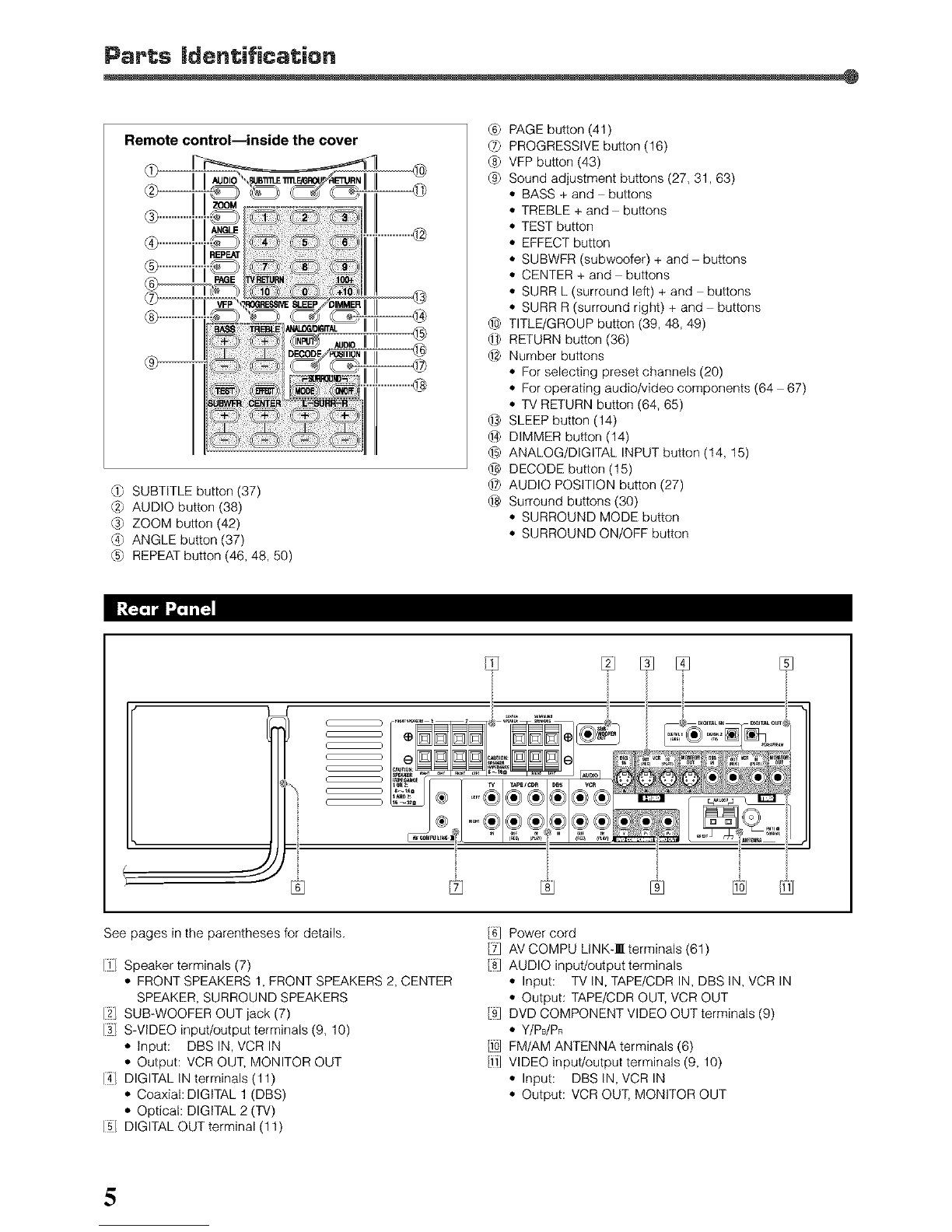
Remote Control ................................................................ 4
Rear Panel ........................................................................ 5
Getting Started ........................................... 6
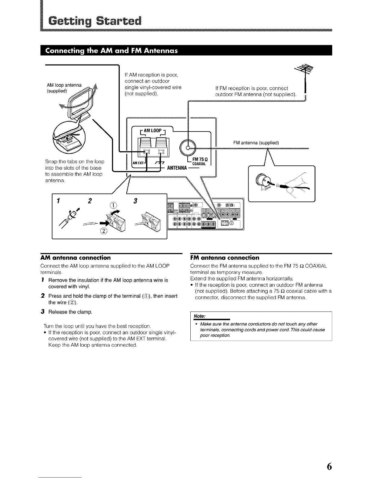
Connecting the AM and FM Antennas ............................. 6
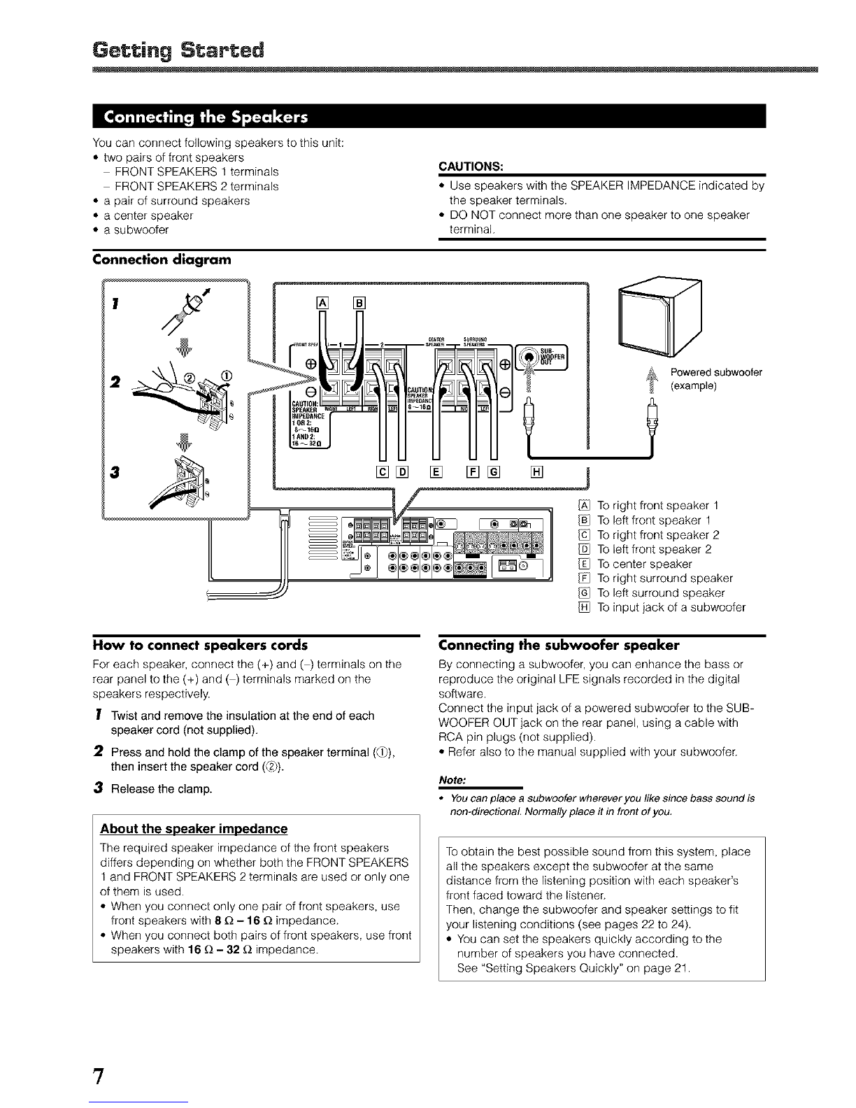
Connecting the Speakers ................................................. 7
Connecting Audio/Video Components ............................. 8
• About connecting cords ............................................ 8
• TV connection ............................................................ 9
• DBS tuner connection ............................................... 9
• VCR connection ....................................................... 10
• Cassette deck/CD recorder connection .................. 10
• Digital connection .................................................... 11
Putting Batteries in the Remote Control ......................... 11
Basic Operations ....................................... 12
Turning On the Power ..................................................... 12
Selecting the Source to Play .......................................... 12
Adjusting the Volume ..................................................... 12
• Listening with headphones ..................................... 13
Selecting the Front Speakers ......................................... 13
Changing the Source Name ........................................... 13
Turning Off the Sound Temporarily ................................. 14
Changing the Display Brightness .................................. 14
Turning Off the Power with the Sleep Timer ................... 14
Selecting the Analog or Digital Input Mode ................... 14
• Changing the digital input mode manually
_or DVD VIDEO only ............................................. 15
Attenuating the Input Signal ........................................... 15
Changing the Scanning Mode ....................................... 16
Activating the Recording Mode ..................................... 16
Basic DVD Player Operations ...................... 17
Tuner Operations ....................................... 19
Tuning in to Stations Manua(ly ........................................ 19
Using Preset Tuning ....................................................... 19
• Storing preset stations ............................................. 19
• Tuning in to a preset station .................................... 20
Selecting the FM Reception Mode ................................. 20
Basic Settings ........................................... 21
Setting Speakers Quickly ............................................... 21
Setting Basic Items ........................................................ 22
• Speaker information ................................................ 23
• Speaker distance .................................................... 23
• Crossover frequency ............................................... 24
• Low frequency effect attenuator .............................. 24
• Dynamic range compression .................................. 24
• Digital input (DIGITAL IN) terminals ........................ 25
• Auto surround .......................................................... 25
• Video output mode .................................................. 25
Sound Adjustments .................................... 26
• Front speaker output balance ................................. 26
• Tone ......................................................................... 27
• Speaker output levels .............................................. 27
• DAP effect level ....................................................... 27
• Subwoofer audio position ........................................ 27
Creating Realistic Sound Fields ................... 28
Activating Surround Mode ............................................. 30
Selecting Surround Modes ............................................. 30
Adjusting Surround Mode Using Remote Control .......... 31
DVD Player Operations .............................. 32
Disc information ............................................................. 32
About the On*screen Bar ............................................... 34
Basic Operation through the On-screen Bar .................. 35
Changing the Time Indication ........................................ 35
Locating a Desired Scene from the Disc Menu ............. 36
Selecting a View Angle .................................................. 37
Selecting the Subtitle Language .................................... 37
Selecting the Audio Language ....................................... 38
Selecting the Audio Channel .......................................... 38
Playing from a Specified Position on a Disc .................. 39
• Locating a desired title/group ................................. 39
• Locating a desired chapter/track ............................ 40
• Locating a desired position ..................................... 40
Special Picture Playback ............................................... 41
• Still picture and frame-by-frame playback .............. 41
• Playing back in slow-motion .................................... 41
• Selecting browsable still pictures
recorded on DVD AUDIO ........................................ 41
• Zooming in ............................................................... 42
• Playing back a bonus group ................................... 42
Changing the VFP Setting .............................................. 43
Program Playback .......................................................... 44
Random Playback .......................................................... 45
Repeat Playback ............................................................ 45
MP3 Disc Playback .................................... 47
Basic Operations ............................................................ 47
Operations through the MP3 CONTROL Screen ............ 48
Repeat Playback ............................................................ 48
JPEG Disc Playback ................................... 49
Slide*show Playback ...................................................... 49
Operations through the JPEG CONTROL Screen .......... 50
Repeat Playback ............................................................ 50
Choice Menu Operations ............................. 51
• Language selection menu LANGUAGE ............... 53
• Picture setting menu PICTURE ............................. 53
• Audio selection menu_UDIQ ............................... 54
.Language code list .............................................. 54
• Speaker setting menu SPK. SETTING .................. 55
• Other setting menu OTHERS ................................ 56
Restricting Playback by Parental Lock .......................... 57
• Setting Parental Lock .............................................. 57
• Changing the Parental Lock setting ........................ 58
• Releasing Parental Lock temporarily ....................... 58
.Country/Area codes list for Parental Lock ........... 59
Glossary for DVD Player ............................ 60
AV COMPU LINK Remote Control System .... 81
Operating JVC's Audio/Video Components ,,, 83
Operating Audio Components .......................................63
Operating Video Components .......................................64
Operating Other Manufacturers'
Equipment ............................................ 65
Changing the Preset Signal Codes ................................ 65
Maintenance ............................................. 68
Troubleshooting ......................................... 69
Specifications ............................................ 72
2

m_m i
%%
See pages in the parentheses for details.
if] O/I STANDBY/ON button and STANDBY lamp (12)
1:2]Disc tray and illumination lamp (17)
13LSource selecting buttons (12)
• DVD, DBS, VCR, TV,TAPE/CDR, FM/AM
14] SOURCE NAME button (13)
15/ DVD player operation buttons (17, 18)
-- (open/close), _ (reverse skip), l..l.q (forward skip),
• (stop), I_ (play), II (pause)
161MASTER VOLUME control (12, 17)
17/ SPEAKERS 1 button (13)
SPEAKERS 2 button (13)
18] DVD AUDIO lamp (17)
/9:1INPUTANALOG/DIGITAL button (14)
INPUT ATT.(attenuator) button (15)
/f0] SURROUND ON/OFF button (30)
/HI SURROUND MODE button (30)
REC (recording) MODE button (16)
If21Display
• For details, see "Display" below.
/f_] SETTING button (21, 22)
@ ADJUST button (26)
/fsI MEMORY button (19, 21)
/f6l CONTROL,A/v/.</_ buttons (15, 19 23, 26)
/f7l 0 (phones)jack (13)
@ Remote sensor (11)
Display
ANALOGDIGPtAL_P£_ DSPSLEEPPROGRAMREPEAT_BP,ANDOf_PROGRESSIVE NPUTATTII
......;CM ........... _/SPK12 RE_/
AUTO_ .... .................... ................
_hl _, _ IIIIIIIIII IIIIIIIIII IIIIIIIIII IIIIIIIIII IIIIIIIIII lllJJm llmlill ilillJ limJi im|Ji lllJim .,_ J_;_11 _ll i_
....................................................................... I._.ih._
M LF_ IIlll Illll Illll Illll Illll Illll Illll Illll Illll IIlll Illll
IIIII IIIII IIIII IIIII IIIII IIIII IIIII IIIII IIIII IIIII IIII1_ MilZil I_ _1 ql
IIIII IIIII IIIII IIIII IIIII IIIII IIIII IIIII IIIII IIIII IIIII
© @ @ @ @ ©@
Q) Input mode indicators (15)
•ANALOG, DIGITAL AUTO
C2)Surround indicators (30)
• AUTO SURROUND, SURROUND
C3)Surround mode indicators (28, 29)
• ITIpL11,DSP
_4) SLEEP indicator (14)
_5) Play mode indicators (44 46)
• PROGRAM, REPEAT l/A-B, RANDOM
_6) PROGRESSIVE indicator (16)
_7) Tuner mode indicators (19, 20)
• TUNED, STEREO, AUTO MUTING
_8) Front speaker indicators (13)
SPK 1/2
INPUT ATT (attenuator) indicator (15)
(_ REC (recording) indicator (16)
@ Sound signal indicators (15)
•PPCM, DRDIGITAL(Dolby Digital), _ (DTS Digital
Surround), LPCM
_2) Signal and speaker indicators (30)
• L, C, R, SUBWFR (Subwoofer), LFE (Low Frequency
Effect), LS, S, RS
_}J RESUME indicator (18)
@ DVD AUDIO indicators (17)
• B.S.P (Browsable Still Picture), BONUS
_) Main display
@ Frequency unit indicators
• kHz (for AM station), MHz (for FM station)
@ Volume indication
@ A.POSITION (audio position) indicator (27)
3

I_3ME_R
DVD-AUDIO/VIDEORECEIVER
TVVOL CHANNEL VOLUME
JVC
RM-SRXDV31J
REMOfECON_L
ml_Ji:_
See pages in the parentheses for details.
/il OPEN/CLOSE button (17)
_/ TV/VIDEO button (17, 64, 65)
/3 Source selecting buttons (12)
*DVD, VCR, DBS, TV, FM/AM, TAPE, CDR
/4] TV VOL (volume) +_ button (64, 65)
/_) CHANNEL +_ button (64 66)
/t Multi operation buttons
* TUNING _ and _ buttons (19)
*FM MODE button (20)
• MEMORY button (20)
[f/ Menu operation buttons
•TOP MENU button (36)
• MENU button (36)
•ENTER button
•Cursor A/v/I,,_/_I buttons
/8] CHOICE button (51,52)
/9] O/l(standby/on) buttons (12, 64 67)
•AUDIO, VCR, DBS, TV
/f0] MUTING button (14)
/ffJ VOLUME +_ button (12, 17)
(f2LQN SCREEN button (34, 35, 37 41,44 46)
To open the cover of the remote controt, push here,
then slide downward.
•For buttons inside the cover, see "Remote control
inside the cover" on page 5.
4

Remote control--inside the cover
_) SUBTITLE button (37)
(2) AUDIO button (38)
(3) ZOOM button (42)
(4) ANGLE button (37)
_5_REPEAT button (46, 48, 50)
(6_ PAGE button (41)
(7_ PROGRESSIVE button (16)
(8) VFP button (43)
C9_Sound adjustment buttons (27, 31,63)
,, BASS + and buttons
*TREBLE + and buttons
', TEST button
', EFFECT button
*SUBWFR (subwoofer) + and buttons
', CENTER + and buttons
*SURR L (surround left) + and buttons
*SURR R (surround right) + and buttons
_ TITLE/GROUP button (39, 48, 49)
_ RETURN button (36)
_-2)Number buttons
', For selecting preset channels (20)
*For operating audio/video components (64 67)
*TV RETURN button (64, 65)
_} SLEEP button (14)
@ DIMMER button (14)
_ ANALOG/DIGITAL INPUT button (14, 15)
@ DECODE button (15)
_ AUDIO POSITION button (27)
@ Surround buttons (30)
*SURROUND MODE button
*SURROUND ON/OFF button
See pages in the parentheses for details. /61 Power cord
/YI AV COMPU LINK-I terminals (61)
/8 AUDIO input/output terminals
*Input: TV IN, TAPE/CDR IN, DBS IN, VCR IN
*Output: TAPE/CDR OUT, VCR OUT
/91 DVD COMPONENT VIDEO OUT terminals (9)
*Y/PdPR
/f0] FM/AM ANTENNA terminals (6)
/1_1VIDEO input/output terminals (9, 10)
*Input: DBS IN, VCR IN
*Output: VCR OUT, MONITOR OUT
If/ Speaker terminals (7)
*FRONT SPEAKERS 1, FRONT SPEAKERS 2, CENTER
SPEAKER, SURROUND SPEAKERS
12] SUB-WOOFER OUT jack (7)
13/ S-VIDEO input/output terminals (9, 10)
*Input: DBS IN, VCR IN
*Output: VCR OUT, MONITOR OUT
14_DIGITAL IN terminals (11)
*Coaxial: DIGITAL 1 (DBS)
*Optical: DIGITAL 2 (TV)
15/ DIGITAL OUT terminal (11)
5

AM loop antenna
(supplied)
Snap the tabs on the loop
into the slots of the base
to assemble the AM loop
_nna,
If AM reception is poor,
connect an outdoor
single vinyFoovered wire
(not supplied).
12 3
ANTENNA
If FM reception is poor, connect /
outdoor FM antenna (not supplied).m
1FM antenna (supplied)
\
AM antenna connection
Connect the AM loop antenna supplied to the AM LOOP
terminals.
?Remove the insulation if the AM loop antenna wire is
covered with vinyl.
2. Press and hold the clamp of the terminal (_)), then insert
the wire (_2)).
3 Release the clamp.
Turn the loop until you have the best reception.
*If the reception is poor, connect an outdoor single vinyF
covered wire (not supplied) to the AM EXT terminal.
Keep the AM loop antenna connected.
FM antenna connec|Jon
Connect the FM antenna supplied to the FM 75 _ CQAXIAL
terminal as temporary measure.
Extend the supplied FM antenna horizontally.
', If the reception is poor, connect an outdoor FM antenna
(not supplied). Before attaching a 75 £2coaxial cable with a
connector, disconnect the supplied FM antenna.
Note:
•Make sure the antenna conductors do not touch any other
terminals, connecting cords and power cord. This could cause
poor reception,
6

You can connect following speakers to this unit:
• two pairs of front speakers
FRONT SPEAKERS 1 terminals
FRONT SPEAKERS 2 terminals
• a pair of surround speakers
• a center speaker
• a subwoofer
CAUTIONS:
• Use speakers with the SPEAKER IMPEDANCE indicated by
the speaker terminals.
• DO NOT connect more than one speaker to one speaker
terminal.
Connection diagram
,y [] []
[] []%
_ Poweredsubwoofer
(example)
[]
IX] Toright front speaker 1
To left front speaker 1
Toright front speaker 2
To left front speaker 2
Tocenter speaker
Toright surround speaker
To left surround speaker
To input jack of a subwoofer
How to connect speakers cords
For each speaker, connect the (+) and ( ) terminals on the
rear panel to the (+) and ( ) terminals marked on the
speakers respectively.
ITwist and remove the insulation at the end of each
speaker cord (not supplied).
2Press and hold the clamp of the speaker terminal (Q)),
then insert the speaker cord (_2_).
3Release the clamp.
About the speaker impedance
The required speaker impedance of the front speakers
differs depending on whether both the FRONT SPEAKERS
1 and FRONT SPEAKERS 2 terminals are used or only one
of them is used.
• When you connect only one pair of front speakers, use
front speakers with 8_- 16 _ impedance.
• When you connect both pairs of front speakers, use front
speakers with 16 _- 32 _ impedance.
Connecting the subwoofer speaker
By connecting a subwoofer, you can enhance the bass or
reproduce the original LFE signals recorded in the digital
software.
Connect the input jack of a powered subwoofer to the SUB-
WQOFER QUT jack on the rear panel, using a cable with
RCA pin plugs (not supplied).
• Refer also to the manual supplied with your subwoofer.
Note:
•Youcanplaceasubwooferwhereveryoulikesincebasssoundis
non-directionaL Normally place it in front of you.
To obtain the best possible sound from this system, place
all the speakers except the subwoofer at the same
distance from the listening position with each speaker's
front faced toward the listener.
Then, change the subwoofer and speaker settings to fit
your listening conditions (see pages 22 to 24).
• You can set the speakers quickly according to the
number of speakers you have connected.
See "Setting Speakers Quickly" on page 21.
7

• Illustrations of the input/output terminals below are typical examples. When you connect other components, refer also to
their manuals since the terminal names actually printed on their rear vary among the components.
•About connecting cords
For video connections
The S-video cords and the component video cord are not
supplied with this unit.
Use the cords supplied with the other components or
purchase them at your dealer.
[] Composite video cord (supplied)
[] S-video cord (not supplied)
[] Component video cord (not supplied)
Green __
Blue
Red
Notes for video connection
•You can use composite video cord or S-video cord for
connecting the DBS tuner and VCR to this unit,
• You can use component video cord in addition to composite
video cord and S-video cord for connecting your TV to this unit.
• By using S-video cord or component video, you can get a better
picture quality--in the order: composite < S-video < component.
• To view the picture from DBS tuner or VCR on your TV, connect
your TV to this unit using the same type of cord for connecting
the DBS tuner or VCR to this unit.
• To view the picture from the built-in DVD player, connect the TV
to this unit using composite video cord, S-video cord, or
component video cord, then register the video output mode
correctly (see "Video output mode" on page 25),
• To enjoy the progressive video picture, connect the TV
compatible with the progressive video input using component
video cord, then change the scanning mode correctly (see
"Changing the Scanning Mode" on page 16).
For audio connections
Connect the external components to this unit with the audio
cords.
Use the cord supplied with the other components or
purchase them at your dealer.
[] Digital coaxial cord (not supplied)
[] Optical digital cord (not supplied)
Notes for digital connection
• When the unit is shipped from the factory, the DIGITAL IN
terminals are set for use with the following components:
-DIGITAL 1 (coaxial): For DBS tuner
-DIGITAL 2 (optical): For TV
• If you connect the CD recorder, change the digital input
(DIGITAL IN) terminal setting (see "Digital input (DIGITAL IN)
terminals" on page 25) and the source name (see "Changing the
Source Name" on page 13) correctly,
• Select the digitalinput mode correctly (see "Selecting the
Analog or Digital Input Mode" on page 14),
[] Audio cord (not supplied)
White __
Red
8

Getting Started
• Illustrations of the input/output terminals below are typical examples. When you connect other components, refer also to their
manuals since the terminal names actually printed on their rear vary among the components.
• TV connection
DO NOT use a TV through a VCR or a TV with a built-in VCR; Otherwise, the picture may be distorted.
Connect using one of the video terminals.
Red
Green reeo....
White
Red
TV
•DBS tuner connection
White
Red
White
Red
9

• VCR connection
Connect using one of the video terminals.
_m_m_m _r,e
m
/
White
4_
J
•,D= /,,,_=
White
White
•Cassette deck/CD recorder connection
]
White
Red
Red
White
Cassette deck
lO

Getting Started
•Digital connection You can connect either of TV
plug,
CD recorder
[] \]
DIGITAL OUT terminal for digital
recording.
I Now, you can plug the power cord of the unit into the AC outlet.
CAUTIONS:
•DO nottouch the power cord with wet hands.
• Do not pull on the power cord to unplug the cord. When
unplugging the cord, always grasp the plug so as not to
damage the cord.
Notes:
•Keep the power cord away from the connecting cords and the
antenna cables, The power cord may cause noise or screen
interference,
• The preset settings such as preset channels and sound adjustment
may be erased in a few days in the following cases:
-When you unplug the power cord,
-When a power failure occurs.
Before using the remote control, put two supplied batteries
first.
1Press and slide the battery
cover on the back of the
remote control.
2Insert batteries. Make sure
to match the polarity: (+) to
(+) and (-) to (-).
3Replace the cover.
If the range or effectiveness of the remote control decreases,
replace the batteries. Use two R6P(SUM-3)/AA(15F) type dry_
cell batteries.
Note:
Supplied batteries are for the initial setup. Replace for continued use.
CAUTION:
Follow these precautions to avoid leaking or cracking cells:
• Place batteries in the remote control so they match the
polarity: (+) to (+) and (-) to (-).
• Use the correct type of batteries. Batteries that look similar
may differ in voltage.
• Always replace both batteries at the same time.
• Do not expose batteries to heat or flame.
When using the remote control,
aim the remote control directly at '
the remote sensor on the unit. o o o OoO
Remote sensor
]!

Press 0/I STANDBY/ON on the front panel or
dollAUDIO on the remote control.
On the front _)anel From the remote control
The STANDBY lamp goes off and the illumination lamp lights
up.
The current source name appears on the display.
• If "DVD" is the current source, "READING" appears while
the unit is detecting the type of the loaded disc (see page
32).
Playback starts automatically when you load some DVD
VIDEO.
"NO DISC" appears on the display when no disc is
loaded.
To turn off the power (into standby)
Press dollSTANDBY/ON on the front panel or dollAUDIO on
the remote control again.
The illumination lamp goes off and the STANDBY lamp lights
up.
Note:
•A small amount of power is consumed even in standby mode. To
turn off the power completely, unplug the AC power cord,
Pressone ofthe source selecting buttons.
On the front _)anel
D_ DB8 VCR TV TA_=_DR _i_M
E ]
From the remote control
END "#OR DB8 "iV
No_s:
•When you have connected some digital components using the
digital terminals (see page 11), register the digital input terminal
setting (see "Digital input (DIGITAL IN) terminals" on page 25) and
digital input mode setting correctly (see "Selecting the Analog or
Digital Input Mode" on page 14). Source name and "DIGITAL"will be
shown on the display when you select the source.
You can use only one of the buttons--TAPE or CDR--whichever
the source name is activated (see "Changing the Source Name" on
page 13).
On the front uanel
To increase the volume, ._._._oLu._'_,
turn MASTER VOLUME clockwise. //// _
TO decrease the volume, ill }1)
turn MASTER VOLUME counterclockwise.
From the remote control VOLUME
TO increase the volume,
press and hold VOLUME +.
To decrease the volume,
press and hold VOLUME .
CAUTION:
Always set the volume to the minimum before starting any
source. If the volume is set at ahigh level, the sudden blast of
sound energy can permanently damage your hearing and/or
ruin your speakers.
Notes:
• The volume level can be adjusted within the range of"O" (minimum)
to "50" (maximum),
• When "DVD'is selected as the source with your TV turned on, the
volume level indication appears on the TV
FM./AM 3APE CDR _L;T _
DVD
DBS
VCR
TV
TAP_CDR
TAPE'_
CDR •
FM/AM
Select the builtqn DVD player.
Select the DBS tuner.
Select the VCR.
Select the TV tuner.
Select the cassette deck or the CD recorder
(front panel ONLY).
Select the cassette deck (remote control
ONLY).
Select the CD recorder (remote control ONLY).
Select an FM or AM broadcast.
12

Basic OpePations
• Listening with headphones
Connect a pair of headphones to the O (phones) jack on the
front panel. This cancels the Surround mode currently
selected, deactivates speakers, and activates the
HEADPHONE mode.
The SPK 1 and 2 indicators go off from the display.
.Disconnecting a pair of headphones from the 0 (phones)
jack cancels the HEADPHONE mode and activates
speakers.
HEADPHONE mode
When using the headphones, the following signals are
output regardless of your speaker setting:
For 2-channel sources, the front left and right channel
signals are output directly from the left and right
headphones.
For multi-channel sources, the front left and right,
center, and surround channel signals are dowmmixed
and then output from the headphones without missing
bass element.
For DVD AUDIO ONLY: When down-mixing is prohibited
on the disc, only signals of the front left and right channel
are output.
CAUTION:
Be sure to turn down the volume:
• Before connecting or putting on headphones, as high
volume can damage both the headphones and your
hearing.
• Before removing headphones, as high volume may come
out of the speakers.
When you have connected two pairs of front speakers, you
can select which to use.
On the front oanel ONLY @
To use both pairs of the speakers
Press SPEAKERS 1 and 2 so that the SPK 1 and 2 indicators
light up on the display.
To use neither pairs of the speakers
Press SPEAKERS 1 and 2 so that the SPK 1 and SPK 2
indicators go off from the display.
Notes:
•ffyou select any of the Surround modes while using both pairs of
the front speakers connected to the FRONT SPEAKERS 1and 2
terminals, the speakers connected to the FRONT SPEAKERS 2
terminals are deactivated.
• While the Surround mode is in use, you can only select either the
speakers connected to the FRONT SPEAKERS 1 or 2 terminals.
When you connect a CD recorder to the TAPE/CDR jacks on
the rear panel, change the source name which will be shown
on the display.
On the front oanel ONLY
Ex.: When changing the source name from "TAPE "to
"CDR"
IPress TAPE/CDR (SOURCE NAME) to select
as the source.
2 Press and hold SOURCE NAME (TAPE/CDR)
until "ASSGN. CDR" appears on the display.
[] [] ,"% _,"' ,'% I I ,"% I_, I"%
= = 'i ',,, ===', = ' ' ' ' '
r"l -, ....,,.J I 'I =i . L_i'=:._ 15
To use the speakers connected to the FRONT SPEAKERS
1terminals
Press SPEAKERS 1 so that the SPK 1 indicator lights up on
the display. (Make sure that SPK 2 isnot lit on the display.)
To use the speakers connected to the FRONT SPEAKERS
2 terminals
Press SPEAKERS 2 so that the SPK 2 indicator lights up on
the display. (Make sure that SPK 1 isnot lit on the display.)
To change the source name to "TAPE"
Press and hold S©URCE NAME (TAPE/CDR) until
"ASSGN TAPE" appears on the display in step 2.
Note:
• Without changing the source name, you can still use the connected
components. However, there may be some inconveniences:
-The unexpected source name wil! appear on the display when you
press TAPE/CDR (SOURCE NAME) on the front panel
-The CDR or TAPE button on the remote control will not work for
selecting the source.
-You cannot use the digital input (see page 25) for the CD
recorde_
]3

From the remote control ONLY MUTING
Press MUTING to mute the sound. \-
"MUTING" appears on the display and the volume turns off
(the volume indication goes off).
.When "DVD" is selected as the source with your TV turned
on, "VOLUME " appears on the TV.
_¢_t_Lane
[] [] j... ;J..j- .j. J;.-'.
llll I I I PJI"J
J; "..' J.J. J; "..J
To restore the sound
Press MUTING again.
.Pressing VOLUME + or on the remote control (or turn
MASTER VOLUME on the front panel) also restores the
sound.
To check or change the remaining time until the shut-off
time
Press SLEEP once.
•The remaining time (in minutes) until the shut-off time
appears.
To change the shut-off time
Press SLEEP repeatedly.
To cancel the Sleep Timer
Press SLEEP repeatedly until "SLEEP 0" appears on the
display. (The SLEEP indicator goes off.)
•Turning off the unit also cancels the Sleep Timer.
Note:
•If Auto Standby (see page 56) and Sleep Timer are used at the
same time, the one with the earlier shut-off time will turn off the
unit,
From the remote control ONLY
PressDIMMER to dim the display. DIMMBq
.Each time you press the button, the display and illumination
lamp dim and brighten alternately.
From the remote control ONLY
PressSLEEP repeatedly. SLEEP
The SLEEP indicator lights up on the display.
.Each time you press the button, the shut-off time changes
as follows: SLEEP indicator
[] [] ...............
, , , , ,, ., .._
•-. Jp" ,-,, p- ij ib•.." hm hm h... I J. _ _:_
When the shut-off time comes
The unit is turned off automatically.
When you have connected digital source components using
both the analog connection and the digital connection
methods (see pages 9 to 11), you can select the input mode.
•Before selecting the digital input mode, register the digital
input terminal setting correctly (see "Digital input (DIGITAL
IN) terminals" on page 25).
Note:
• You cannot change the input mode when selecting "DVD"as the
source. Digital input is always used for the built-in DVD player
IPress one of the source selecting buttons
(DBS, TV, or CDR) for which you want to
change the input mode.
2 Press INPUT ANALOG/DIGITAL (INPUT ATT.)
on the front panel or ANALOG/DIGITAL
INPUT on the remote control.
_I_L_LOG/DIGffN.
On the front Danel From the remote control
The current input mode appears on the display.
.Each time you press the button, the input mode
alternates between the analog input ("ANALOG") and
the digital input ("DGTL AUTO").
DIGITALAUTO indicator
[] [] I"..". "I" ; .". I; "I" .".
' '" ' ' '""" 15
i.." :...i i "... r"i :...: i:..:
TQ BE CONTINUED TQ THE NEXT PAGE
14

Basic OpePations
DGTL AUTO Select for the digital input mode.
The DIGITAL AUTO indicator lights up.
The unit automatically detects the
incoming signal format, then the sound
signal indicator for the detected signal
(see below) lights up; otherwise, no
sound signal indicators light up.
ANALOG Select for the analog input mode (initial
setting except for the built-in DVD
player).
The ANALOG indicator lights up.
Sound sianal indicators on the disolav
PPCM Light when DVD AUDIO Packed PCM signals
come in.
r]rlulerrAL • Light when Dolby Digital signals come in.
• Flash when "DGTL D.D." is selected for
software not encoded with Dolby Digital
signals.
• Light when DTS signals come in.
• Flash when "DGTL DTS" is selected for
software not encoded with DTS signals.
LPCM Light when Linear PCM signals come in.
•Changing the digital input mode
manually--for DVD VIDEO only
Ifthe following symptoms occur while Dolby Digital or DTS
software is played back, try changing the digital input mode:
•Sound does not come out at the beginning of playback.
•Noise comes out while searching for or skipping chapters
or tracks.
1Press INPUT ANALOG/DIGITAL (INPUT ATT.)
on the front panel or ANALOG/DIGITAL
INPUT on the remote control to select
"DGTL AUTO."
_ar_ ANALOG_IGITAL
On the front oanel From the remote control
2Press CONTROL =,-(or <) to r_;
select "DGTL D.D." or "DGTL _ ='"= @
DTS" while "DGTL AUTO" still
remains on the display.
• Each timeyou press the button, the digital input mode
changes as follows:
[] [] r',,=-.-"i =-.." i"i-="=
DGTL D.D. Select for playing back software
encoded with Dolby Digital.
The r]rlulerrAL indicator lights up*.
DGTL DTS Select for playing back software
encoded with DTS.
The _ indicator lights up*.
* These indicators flash when no signal or a signal
without the proper format is played back.
You can also change the digital input mode by DECODE
pressing DECODE repeatedly on the remote
control.
Notes:
•When "DGTL AUTO"cannot recognize the incoming signals, no
sound signal indicators light up on the displa_
• When you turn off the unit or select another source, "DGTL DTS"
and "DGTL L2D,"are canceled,
The digital input mode is automatically reset to "DGTL AUTO."
When the input level of the analog source is too high, the
sounds will be distorted. If this happens, attenuate the input
signal level to prevent this sound distortion.
• You have to make this adjustment for each analog source.
On the front oanel ONLY
Press and hold INPUT ATT. (INPUT ANALOG/DIGITAL)
until the INPUT ATT indicator lights up on the display.
• Each time you press and hold the button, the input
Attenuator turns on ("ATT ON") or off ("ATT NORMAL").
[] []
INPUT ATT indicator
="="i==r' ="=i, i ,_'_15J J
l,,,l l l I I l '."
I I I I %,,' I |
ATT NORMAL Normally select this (initial setting).
The analog sound is not attenuated.
ATT ON Select when the analog sound is distorted.
15

This unit supports the progressive scanning system (480p '_)
as well as the conventional interlaced scanning system
(480i_).
If your TV has component video jacks and supports
progressive video input, you can enjoy a high quality picture
from the builtqn DVD player.
,Refer also to the instruction manuals supplied with your TV.
,You can select the picture source according to the original
picture type (film or video source). See "PICTURE
SOURCE" on page 53.
,Do not change the scanning mode to "PROGRESSIVE" in
the following cases:
When your TV does not support the progressive video
input.
When you are not connecting your TV to the unit using a
component video cord.
From the remote control ONLY PROGRE_IVE
Press PROGRESSIVE when "DVD" is selected as the
source.
,Each time you press the button, the scanning mode
changes between "INTERLACE" and "PROGRESSIVE."
INTERLACE Select for conventional TV (initial setting).
PROGRESSIVE Select ifyour TV with component jacks
supports the progressive video input. The
PROGRESSIVE indicator lights up.
Notes:
•Some progressive TVs and High-Definition TVs are not fully
compatible with this system, When an incompatible picture is played
back, change the scanning mode to "INTERLACE." To check the
compatibility of your TV, contact your deale_
All JVC progressive TVs and High-Definition TVs are fully
compatible with this system,
• When you select "PROGRESSIVE" as the scanning mode, the
picture does not come out correctly through composite video and
S-video jacks.
4SOp and 480i indicate the number of scanning lines and scanning
format of an image signal
-480p indicates 480 scanning lines with progressive format,
-480i indicates 480 scanning lines with interlaced format.
When you play back the multi_channel sources, Recording
mode enables you to record the sounds without missing
surround elements by down-mixing the center and surround
channel signals into the front channel signals.
•When multi_channel software is played back with
Recording mode activated, the sounds are down-mixed
and come out through the front speakers only.
• For DVD AUDIO ONLY: When dowmmixing is prohibited
on the disc, this function does not take effect.
On the front panel ONLY
Press and hold REC MODE (SURROUND MODE) until
"RECMODE ON" appears on the display.
The REC indicator lights up on the display. REC indicator
_Y_LAIJ"rO _)
Each time you press and hold the button, Recording mode
is activated ("RECMODE ON") and deactivated
("RECMODE OFF") alternately.
RECMODE OFF Normally select this (initial setting).
Down-mixing iscanceled.
RECMODE ON Select for recording dowmmixed sounds.
When recording onto the VCR:
You can record the picture on your video tape without the
volume level indication on the TV when Recording mode is
activated.
•When you do not want to record the omscreen guide icons,
see page 56.
•The choice menu (see page 51) and on-screen bar (see
page 34) are always recorded when they appear on the TV.
CAUTION:
Sound coming out of the speakers may be distorted by
Recording mode. In this case, decrease the volume until the
sound distortion diminishes.
Notes:
•Whenyouturnofftheunitorselectanothersource, Recording
mode is canceled ("RECMODE OFF").
• Sound adjustments (see pages 26 and 27) and Surround modes
(see pages 28 to 31) do not affect the recording,
• The following buttons do not work while Recording mode is
activated ("RECMODE ON"):
-SETTING and ADJUST on the front panel
-SURROUND ON/OFF and SURROUND MODE on the front panel
-Sound adjustment buttons on the remote control
16

For details about DVD player operations, see pages 32 to
46.
.You can also play back MP3 and JPEG files. See pages 47
to 50.
•Before using the remote control, press DVD so that the
remote control works for the DVD player.
Before turning on the unit, turn on your TV and select the
correct video input (refer to the manual supplied with your
TV).
.When you use a JVC's TV, you can turn on your TV by
pressing TV VII on the remote control and select the video
input by pressing TV/VIDEO. (If your TV is not a JVC, see
"Operating Other Manufacturers' Equipment" on page 65.)
.For changing the OSD messages_he information on the
TWinto the desired language, see pages 51 to 53.
IPress Aon the front panel or OPEN/CLOSE
on the remote control to open the disc tray.
OPEN/CLOSE
On the front panel From the remote control
The unit is turned on and the disc tray opens.
The STANDBY lamp goes off and the illumination lamp
lights up.
', When a disc is already loaded, pressing I,.-turns on the
unit and starts playing back the loaded disc.
2 Load a disc.
Place a disc correctly with its label side up.
CORRECT
INCORRECT
3Press _.
The disc tray closes and the unit starts playing back the
loaded disc.
IH_(D iO
On the front panel From the remote control
.You can also close the disc tray by pressing --_on the
front panel or OPEN/CLOSE on the remote control.
4Adjust the volume.
VOLUME
On the front panel From the remote control
To activate and select Surround mode, see page 30.
About the indication on the display while playing back
a disc
While you are playing back a disc, the playback
information appears on the display as follows:
Ex.: When playing back a DVD VIDEO
UB_[]D[] ,,, • • ... .. i .....
[_ i ' 'i 'i [] i..i i_i :: i..i .: ir
l
9: (2)
Q_ Chapter number
_2) Elapsed playing time
Ex.: When playing back a DVD AUDIO •
... ... .. i .....
[_ 'i i.: i..i [] i..i i_i Hi..i ,,'
[] [] =:=- '...= =:..=[] =:..==:." ==--= i
t,L-.r j 15
Q) B.S.P (Browsable Still Picture) indicator (lights up when
you play back still pictures)
_2) BONUS indicator (lights up when the disc has a bonus
group.)
_3) Group number
_4) Track number
@Elapsed playing time
Ex.: When playing back an audio CD
[] [] .... ,1 ,,-. ,, ,--,,,,,,
_,[_ i ' i ", , l.a. :: ..' ...
@ Track number
_2) Elapsed playing time
When a DVD AUDIO is loaded, the DVD AUDIO lamp
lights up on the front panel.
DVD AUDIO
Ic
17
Other manuals for RX-DV31SL
2
Table of contents
Other JVC Home Theater System manuals