JVC SW-D8000U User manual

SW-D8000U, 16CH. COLOR VIDEO MULTIPLEXER
JVC PROFESSIONAL, IMAGING PRODUCTS 1
50
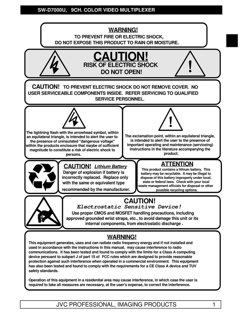
CAUTION!
RISK OF ELECTRIC SHOCK
DO NOT OPEN!
CAUTION! TO PREVENT ELECTRIC SHOCK DO NOT REMOVE COVER. NO
USER SERVICEABLE COMPONENTS INSIDE. REFER SERVICING TO QUALIFIED
SERVICE PERSONNEL.
The lightning flash with the arrowhead symbol, within
an equilateral triangle, is intended to alert the user to
the presence of uninsulated "dangerous voltage"
within the products enclosure that maybe of sufficient
magnitude to constitute a risk of electric shock to
persons.
The exclamation point, within an equilateral triangle,
is intended to alert the user to the presence of
important operating and maintenance (serviceing)
instructions in the literature accompanying the
product.
CAUTION! Lithium Battery
Danger of explosion if battery is
incorrectly replaced. Replace only
with the same or equivalent type
recommended by the manufacturer.
ATTENTION
This product contains a lithium battery. This
battery may be recyclable. It may be illegal to
dispose of this battery improperly under local,
state or federal laws. Check with your local
waste management officials for disposal or other
possible recycling options.
CAUTION!
Electrostatic Sensitive Device!
Use proper CMOS and MOSFET handling precautions, including
approved grounded wrist straps, etc., to avoid damage this unit or its
internal components, from electrostatic discharge .
WARNING!
This equipment generates, uses and can radiate radio frequency energy and if not installed and
used in accordance with the instructions in this manual, may cause interference to radio
communications. It has been tested and found to comply with the limits for a Class A computing
device persuant to subpart J of part 15 of FCC rules which are designed to provide reasonable
protection against such interference when operated in a commercial environment. This equipment
has also been tested and found to comply with the requirements for a CE Class A device and TUV
safety standards.
Operation of this equipment in a residential area may cause interference, in which case the user is
required to take all measures are necessary, at the user's expense, to correct the interference.
WARNING!
TO PREVENT FIRE OR ELECTRIC SHOCK,
DO NOT EXPOSE THIS PRODUCT TO RAIN OR MOISTURE.

SW-D8000U, 16CH. COLOR VIDEO MULTIPLEXER
2JVC PROFESSIONAL, IMAGING PRODUCTS
IMPORTANT SAFETY INFORMATION
lRead Instructions -All the safety and operating instructions should be read before the unit is operated.
lRetain instructions -The safety and operating instructions should be retained for future reference.
lHeed Warnings -All warnings on the unit and in the operating instructions should be adhered to.
lFollow Instructions -All operating and use instructions should be followed.
lCleaning -Unplug the unit from the outlet before cleaning. Do not use liquid cleaners or aerosol cleaners.
Use a damp cloth for cleaning.
lAttachments -Do not use attachments not recommended by the product manufacturer as they may cause
hazards.
lWater and Moisture -Do not use this unit near water -for example, near a bath tub, wash bowl, kitchen sink,
or laundry tub, in a wet basement, near a swimming pool, in an unprotected outdoor installation, or any area
which is classified as a wet location.
lAccessories -Do not place this unit on an unstable stand, tripod, bracket, or mount. The unit may fall,
causing serious injury to a person and serious damage to the unit. Use only with accessories recommended
by the manufacturer, or sold with the product. Any mounting of the unit should follow the manufacturer's
instructions, and should use a mounting accessory recommended by the manufacturer.
lVentilation -Openings in the enclosure, if any, are provided for ventilation and to ensure reliable operation of
the unit and to protect it from overheating. These openings must not be blocked or covered. This unit should
not be placed in a built-in installation unless proper ventilation is provided. Do not place directly on other hot
equipment that may increase its operating temperature.
lPower Sources -This unit should be operated only from the type of power source indicated on the marking
label. If you are not sure of the type of power supply you plan to use consult your appliance dealer or local
power company. For units intended to operated from battery power, or other sources, refer to the operating
instructions.
lGrounding or Polarization -This unit may be equipped with a polarized alternating-current line plug (a plug
having one blade wider than the other). This plug will fit into the power outlet only one way. This is a safety
feature. If you are unable to insert the plug fully into the outlet, try reversing the plug. If the plug should still
fail to fit, contact your electrician to replace your obsolete outlet. Do not defeat the safety purpose of the
polarized plug.
lAlternately this unit may be equipped with a 3-wire grounding-type plug, a plug having a third (grounding) pin.
This plug will only fit into a grounding-type power outlet. This is a safety feature. If you are unable to insert
the plug into the outlet, contact your electrician to replace your obsolete outlet. Do not defeat the safety
purpose of the grounding-type plug.
lPower-Cord Protection -Power-supply cords should be routed so that they are not likely to be walked on or
pinched by items placed upon or against them, paying particular attention to cords at plugs, convenience
receptacles, and the point where they exit from the appliance.
lPower Lines -An outdoor system should not be located in the vicinity of overhead power lines or other electric
light or power circuits, or where it can fall into such power lines or circuits. When installing an outdoor system,
extreme care should be taken to keep from touching such power lines or circuits. When installing an outdoor
system, extreme care should be taken to keep from touching such power lines or circuits as contact with them
might be fatal.
lOverloading -Do not overload outlets and extension cords as this can result in a risk of fire or electric shock.

SW-D8000U, 16CH. COLOR VIDEO MULTIPLEXER
JVC PROFESSIONAL, IMAGING PRODUCTS 3
CAUTION
ATTENTION
RISK OF ELECTRIC SHOCK DO NOT OPEN
lObject and Liquid Entry -Never push objects of any kind into this unit through openings as they may touch
dangerous voltage points or short-out parts that could result in a fire or electric shock. Never spill liquid of any
kind on the unit.
lServicing -Do not attempt to service this unit yourself as opening or removing covers may expose you to
dangerous voltage or other hazards. Refer all servicing to qualified service personnel.
lDamage Requiring Service -Unplug the unit from the outlet and refer servicing to qualified service personnel
under the following conditions:
a) When the power-supply cord or plug is damaged.
b) If liquid has been spilled, or objects have fallen into the unit.
c) If the unit has been exposed to rain or water.
d) If the unit does not operate normally by following the operating instructions. Adjust only those controls
that are covered by the operating instructions as an improper adjustment of other controls may result in
damage, or void the warranty, and will often require extensive work by a qualified technician to restore
normal operation.
e) If the unit has been dropped or the cabinet has been damaged.
f) When the unit exhibits a distinct change in performance, this indicates a need for service.
lReplacement Parts -When replacement parts are required be sure the service technician has used
replacement parts specified by the manufacturer or that they have the same characteristics. Unauthorized
substitutions may result in fire, electric shock or other hazards.
lSafety Check -Upon completion of any service or repairs to this unit, ask the service technician to perform
safety checks to determine that the unit is in proper operating condition.
lCoax Grounding -If an outside cable system is connected to the unit, be sure the cable system is grounded.
Lightning -For added protection of this unit during a lightning storm, or when it is left unattended and unused
for long periods of time, unplug it from the wall outlet and disconnect the cable system. This will prevent
damage to the unit due to lightning and power-line surges.
SAFETY PRECAUTIONS
TO REDUCE THE RISK OF ELECTRICAL SHOCK, DO NOT OPEN COVERS. NO USER
SERVICEABLE PARTS INSIDE. REFER SERVICING TO QUALIFIED SERVICE PERSONNEL.
This label may appear on the bottom of the unit due to space limitations.
The lightning flash with an arrowhead symbol, within an equilateral triangle, is intended to alert the user to the
presence of uninsulated "dangerous voltage" within the product's enclosure that may be of sufficient magnitude
to constitute a risk of electric shock to persons.

SW-D8000U, 16CH. COLOR VIDEO MULTIPLEXER
4JVC PROFESSIONAL, IMAGING PRODUCTS
The exclamation point within an equilateral triangle is intended to alert the user to presence of important
operating and maintenance (servicing) instructions in the literature accompanying the appliance.
Lithium Battery Warning / Lithiumbatterien
CAUTION:
Danger of explosion if battery incorrectly replaced. Replace only with the same or
equivalent type recommended by the manufacturer. Dispose of used batteries according to
manufacturer’s instructions.
WARNING: Electrostatic-sensitive device.
Use proper CMOS/MOSFET handling precautions to avoid electrostatic discharge.
NOTE: Grounded wrist straps must be worn and proper ESD safety precautions observed when handling
the electrostatic-sensitive printed circuit boards.
UNPACKING
The shipping carton is the safest container in which the unit may be transported. Save it for possible future use.
EMISSIONS
The equipment complies to CE class A and to part 15 of the FCC rules for emissions, class A.
SERVICE
If technical assistance is required, please contact our Technical Support Engineer at 800-526-5308,
extension 5234. (Monday through Friday, 9:00 am –5:00 pm EST excluding holidays).
If the unit ever requires factory service, the customer should:
A. Pack the product carefully, preferably in the original carton,
B. Include a copy of your bill of sale,
C. Include a detailed letter of explanation of the problem,
D. Ship prepaid and insured to the following address:
JVC Professional Service
705 Enterprise Street
Aurora, IL 60504-8149
630-851-7855 Voice
630-851-0036 Fax
Refer to the SERVICE section in this manual.

SW-D8000U, 16CH. COLOR VIDEO MULTIPLEXER
JVC PROFESSIONAL, IMAGING PRODUCTS 5
Passwords
This page contains the system passwords. It is recommend that, for system security, you
remove it from the manual and store it in a safe place.
The initial password, supplied with the unit for the Operator menu system, is:
Password 1,
The password for the Installer menus is:
Password 2,
The password for resetting your multiplexer to the factory settings is:
Password 3,
You should change the password for the menu systems (passwords 1 & 2) and record it
below for future reference.
Password 1.
_________________________________________________________________
Password 2.
_________________________________________________________________

SW-D8000U, 16CH. COLOR VIDEO MULTIPLEXER
6JVC PROFESSIONAL, IMAGING PRODUCTS
This page intentionally left blank

SW-D8000U, 16CH. COLOR VIDEO MULTIPLEXER
JVC PROFESSIONAL, IMAGING PRODUCTS 7
TABLE OF CONTENTS
1.0 INSTALLATION INSTRUCTIONS ....................................................................................10
1.1 UNPACKING ..............................................................................................................10
1.2 ASSOCIATED EQUIPMENT.......................................................................................10
1.3 LOCATION .................................................................................................................10
2.0 PRODUCT DESCRIPTION...............................................................................................10
2.1 FRONT PANEL CONTROLS......................................................................................13
2.2 CONNECTIONS..........................................................................................................13
2.3 CAMERA INPUTS ......................................................................................................14
2.4 VCR CONNECTIONS.................................................................................................14
2.5 MONITOR CONNECTIONS........................................................................................15
2.6 ALARM INPUTS AND OUTPUTS...............................................................................15
2.7 ALARM INPUTS .........................................................................................................16
2.8 ALARM OUTPUTS .....................................................................................................16
2.9 VEXT INPUT...............................................................................................................17
2.10 POWER ......................................................................................................................17
3.0 LIVE MODE OPERATION................................................................................................18
3.1 MONITOR DISPLAYS ................................................................................................18
3.1.1 MULTI-SCREEN DISPLAYS ON MONITOR-A.................................................... 18
3.1.2 CHANGING CAMERAS IN MULTI-SCREEN DISPLAYS .................................... 18
3.1.3 FULL-SCREEN DISPLAYS ON MONITOR-A...................................................... 19
3.1.4 AUTOLIST™........................................................................................................ 20
3.1.5 PIP DISPLAY: SIZE AND POSITION................................................................... 20
3.1.6 CHANGING POSITIONS AND COLORS OF TITLES.......................................... 20
3.1.7 MONITOR-B DISPLAYS...................................................................................... 21
3.2 RECORDING..............................................................................................................21
3.2.1 MONITOR OUTPUTS IN RECORD MODE.......................................................... 22
3.2.2 ALARM DISPLAYS IN RECORD MODE ............................................................. 22
3.3 PLAYBACK ................................................................................................................22
3.3.1 PLAY MODE: MONITOR-A DISPLAYS............................................................... 22
3.3.2 PLAY MODE: MONITOR-A INDICATIONS.......................................................... 23
3.3.3 PLAY MODE: MONITOR-B DISPLAYS............................................................... 24
3.3.4 PLAY MODE: CHANGING TEXT POSITIONS AND COLORS............................ 24
3.3.5 PLAY MODE: SEQUENCING DURING PLAYBACK........................................... 24
3.3.6 ADJUSTING PLAYBACK BRIGHTNESS AND CONTRAST. .............................. 25
3.4 ALARMS.....................................................................................................................25
3.4.1 MANUAL ALARM ACTIVATION ( PSEUDO ALARM ) ........................................ 25
3.4.2 ALARM DISPLAYS IN LIVE MODE..................................................................... 26
3.4.3 ALARM DISPLAYS IN PLAY MODE ................................................................... 26
3.4.4 ALARM INDICATORS.......................................................................................... 27
3.4.5 CLEARING ALARMS........................................................................................... 27
3.4.6 ALARM HISTORY................................................................................................ 27
3.5 MOTION DETECTION................................................................................................27
3.5.1 ACTIVITY DETECTION........................................................................................ 27
3.6 SPECIAL FUNCTIONS...............................................................................................28
3.6.1 VIDEO LOSS....................................................................................................... 28
3.6.2 FREEZE OPERATION......................................................................................... 28

SW-D8000U, 16CH. COLOR VIDEO MULTIPLEXER
8JVC PROFESSIONAL, IMAGING PRODUCTS
3.6.3 ZOOM 29
3.6.4 SELECTING VCR AS AN INPUT (VCR VIEW) ...................................................29
3.6.5 SUMMER / WINTER TIME CHANGE...................................................................29
3.6.6 MACRO FUNCTIONS ..........................................................................................30
3.7 OPERATOR MENUS ................................................................................................. 31
3.7.1 OPERATOR MENU ITEMS..................................................................................33
3.7.2 NAVIGATING THE OPERATOR MENU SYSTEM ............................................... 33
3.7.3 THE AVAILABLE MENUS....................................................................................34
3.7.4 THE OPERATOR MENU......................................................................................34
3.7.5 FIELD/FRAME SETTING ..................................................................................... 34
3.7.6 SEQUENCING .....................................................................................................35
3.7.7 TIME/DATE DISPLAY..........................................................................................35
3.7.8 TITLES DISPLAY................................................................................................. 35
3.7.9 PLAYBACK FORMAT..........................................................................................36
3.7.10 ALARM HISTORY............................................................................................... 37
3.7.11 OPERATOR PASSWORD................................................................................... 37
3.7.12 NORMAL RECORD SPEED ...............................................................................37
3.7.13 SYSTEMVIEW MENU......................................................................................... 39
4.0 MENU PROGRAMMING AND SETUP ............................................................................ 40
4.1 INITIAL POWER UP .................................................................................................. 40
4.2 USING THE MENU SYSTEM..................................................................................... 40
4.3 BATTERY BACKED-UP MEMORY FOR MENU OPTIONS....................................... 41
4.4 NAVIGATING THE FOUR MENU LEVELS................................................................ 41
4.5 TIME/DATE SET UP .................................................................................................. 42
4.6 SEQUENCE SET UP ................................................................................................. 43
4.7 AUTOLIST™.............................................................................................................. 44
4.8 RECORD SET UP...................................................................................................... 44
4.9 ALARM SET UP......................................................................................................... 47
4.10 MACROS................................................................................................................... 54
4.11 MOTION DETECTION ............................................................................................... 57
4.12 CAMERA TITLES SET UP......................................................................................... 64
4.13 CAMERA SET UP...................................................................................................... 65
4.14 VCR SETUP............................................................................................................... 69
4.15 COMMUNICATIONS.................................................................................................. 71
4.16 FRONT PANEL LOCK............................................................................................... 73
4.17 FACTORY SETTINGS ............................................................................................... 73
4.18 PASSWORDS............................................................................................................ 73
5.0 WARRANTY .................................................................................................................... 75
6.0 RS-232 REMOTE PROTOCOL........................................................................................ 77
7.0 TECHNICAL SPECIFICATIONS:..................................................................................... 82
8.0 LIST OF MACRO FUNCTIONS ....................................................................................... 85
9.0 LIST OF SCHEDULED MACROS.................................................................................... 86
10.0 SYSTEM CONFIGURATION ........................................................................................... 87

SW-D8000U, 16CH. COLOR VIDEO MULTIPLEXER
JVC PROFESSIONAL, IMAGING PRODUCTS 9
CONTROLS AND INDICATORS
FRONT PANEL CONTROLS
REAR PANEL CONNECTIONS
ALT {F}
3
11
2
10
1
9
4
12
7
15
6
14
5
13
8
16
MULTIPLEXER SW-D8000U
MENU
MenuArrow Key
EnterRecordLive Play
ALT Alarm Zoom
FreezeSequenceFunction
FRZZOOMSEQALMFNALTSPOTMULTI
LIVE REC PLAY
POWER
Camera Select Key 1-16
B
12345678910 11 12 13 14 15 16
RS-232-1 SVHSSVHS
1 RS-485 2
12 VDC
Alarm, Vext & Accessory
connections, DB-25 RS-232C RS-485 Monitor A outputs
composite, Y/C VCR inputs
composite, Y/C
Monitor B output
composite VCR outputs
Y/C, composite
12V DC power,
center positive
Camera BNC inputs
1-16 looping

SW-D8000U, 16CH. COLOR VIDEO MULTIPLEXER
10 JVC PROFESSIONAL, IMAGING PRODUCTS
1.0 INSTALLATION INSTRUCTIONS
1.1 UNPACKING
Keep the original packing of use when the unit has to be stored or transported. The packaging
should contain the following items;
qThe multiplexer unit
qA power supply
qInstruction Manual
Be sure to check the unit for signs of damage. If damage has occurred, please contact the supplier
and the delivery service immediately. Do not attempt to use the unit.
1.2 ASSOCIATED EQUIPMENT
A typical system, using this multiplexer, could contain the following components;
qTwo monitors
qRecorder
qSecurity Cameras with 1Vp-p composite video outputs
q75 ohm BNC connectors and video coaxial cable for connecting the video signals
1.3 LOCATION
Make sure your AC power supply outlet is stable and within the rated voltage of the external DC 12V
power supply provided with the unit. If the site’s AC power is likely to have spikes for power drops,
use power line conditioning or uninterruptable powers supply (UPS).
Ventilation:
Make sure that the location planned for the installation of the unit is well ventilated. Locate the
cooling vents in the unit enclosure and make sure they are not obstructed in the installation.
Temperature:
Make sure to check the ambient temperature specifications of the unit and insure that the location of
installation is within these specifications. Extremes of heat or cold outside of the specified limits may
cause the unit to fail.
Do not install the unit near hot equipment. You can place a monitor on top of the unit if it weighs less
than 35lbs (16kg)
2.0 PRODUCT DESCRIPTION
This manual describes the installation, operation and programming of the SW-D8000U color duplex
multiplexers.
The SW-D8000U multiplexer is designed as acolor video record and Playback system. This unit allows the
simultaneous recording of multiple camera inputs on a security recording devices. Live video inputs and
recorded video when Played-back can also be viewed in several different multi-screen configurations.
These units contain dual digital video processors so that multiplexed recording can always take place, even
during Live mode multi-screen displays or during Playback of previously recorded multiplexed signals. The

SW-D8000U, 16CH. COLOR VIDEO MULTIPLEXER
JVC PROFESSIONAL, IMAGING PRODUCTS 11
SW-D8000U is a single integrated unit, housed in a 19" rack-mountable enclosure. The front panel contains
all operator control keys and indications, while the looping video inputs, the video outputs, the alarm inputs
and outputs, and the remote control connectors are housed on the rear panel. It has DC 12V power and is
supplied with an external AC power supply.
The SW-D8000U has two monitor outputs, designated Monitor-A and Monitor-B.
qMonitor-A is used for multi-screen, digital images that can be frozen and zoomed.
qMonitor-B is a full-screen, Live, analog output. Monitor-B is sometimes referred to as a ‘spot’ monitor
in the security industry.
The SW-D8000U includes many advanced features;
qEasy setup and programming using modern style on-screen menus
qMenu adjustable camera AGC (automatic gain control)
qHigh quality color definition –CCIR 601 4:2:2 YUV
qS-VHS to Monitor-A
qAutomatic video input termination
qVEXT VCR clock input for automatic synchronization to VCR speeds
qActivity/Motion detection
qMultiple Alarm inputs and outputs
qMotion Detection Sensitivity Scope for simplified set-up
q“Covert” Camera setting
qConditional Live Display
qAutoListsimplified sequence programming
q2X digital zoom and digital pan & tilt –Live & Playback
qAlarm history log
qOperator programmable macro function keys
qA scheduler to automatically start macros at preset times, days or dates
qA simple Summer/Winter time change function
qRemote programming (upload and download)
qRemote control using optional keyboard or PC
qOptional Pan Tilt and Zoom controls
qAbility to decode tapes recorded on multiplexers manufactured by Dedicated Micros,Robot, and
Calibur allowing existing DM and Robot sites to upgrade to the advanced features of the SW-D8000U
multiplexers
WARNING!
The primary purpose of the SW-D8000U is efficient video multiplexing and multi-
screen display. Alarm handling and motion detection are secondary functions.
National standards relating to alarm equipment should be taken into account when
choosing equipment to use with the SW-D8000U. In general, the SW-
D8000U
multiplexer should not be the only alarm device on the site.

SW-D8000U, 16CH. COLOR VIDEO MULTIPLEXER
12 JVC PROFESSIONAL, IMAGING PRODUCTS
How multiplexed recording works:
To record several camera inputs on one video output, single fields are digitally captured from each of the
video-input channels and then stacked consecutively to form a continuous video signal of time-sliced camera
fields. The time slicing of several inputs onto one output is generally known as Time Division Multiplexing
(TDM). Time base correction is performed during digital capture and so input cameras need not be
synchronized.
The order in which the fields are captured from the different input cameras is controlled by an operator-
programmed RECORD LIST, which can be automatically modified by the system in the event of alarms or
motion detection. The multiplexed video fields can then be recorded onto a single VCR via the VCR output
connector.
Example: 3 multiplexed inputs:
A1 A2 A3 A4 A5 A6 A6 A7
B1 B2 B3 B4 B5 B6 B6 B7
C1 C2 C3 C4 C5 C6 C6 C7
Input:
Camera A video fields:
Input:
Camera B video fields:
Input:
Camera C video fields:
A1 B2 C3 A4 B5 C6 A6 B7
Output:
Multiplexed video stream to VCR
etc.
etc.
etc.
etc.
In addition to the video content sent to the VCR in each field, a packet of digital data that uniquely identifies
the field is inserted into each field sent to the VCR. (This packet data is not visible in the normal video and is
used in the Playback mode to recognize incoming fields and to link them back to the original camera input
from which they were captured.)
Besides the camera number, other status information stored in this packet of digital data includes time and
date, camera status, camera title, selected record time mode information as well as system and alarm status
at the time of recording. This status information is rebuilt and displayed with the corresponding camera
during Playback. On Playback the operator can select one of several screen formats for display, and can
also choose which cameras to display in which position in a multi-screen.
NOTE: The SW-D8000U will NOT set the VCR speeds which must be set up separately on the VCR.
How Playback works:
When Playing back multiplexed recordings which were originally recorded from aSW-D8000U compatible
multiplexer, time stamped video fields are received from a VCR connected to the VCR input connector or Y/C
input on the SW-D8000U's rear panel, each field being uniquely identified by its own digital data packet.
These embedded digital data packets are decoded, and the video field is linked to its original input camera.
The operator can select which cameras to display during Playback, and so the video field for that camera is
displayed (or skipped) according to the operator's Playback selection. All the associated status information,
including titles, time and date of recording, as well as the alarm or video loss status of the camera is
reconstructed from the digital data packet and displayed as on-screen text during Playback. Because the
on-screen text is re-constructed and generated for on-screen display (as opposed to being recorded on the

SW-D8000U, 16CH. COLOR VIDEO MULTIPLEXER
JVC PROFESSIONAL, IMAGING PRODUCTS 13
VCR as part of the video display) the operator is assured of very clear and legible status and titles during
Playback.
2.1 FRONT PANEL CONTROLS
The front panel contains all the operator control keys and indicators, while the video inputs, video
outputs, alarm inputs and outputs, and the remote control connections are on the rear panel.
The unit has DC 12V power and is supplied with an external AC power supply
FRONT PANEL CONTROLS
2.2 CONNECTIONS
The following instructions relate to the multiplexer only. Refer to the relevant instructions for the
associated equipment.
All the connectors are on the back-panel of your multiplexer as shown below. These connectors are:
q16 Loop-through camera inputs with automatic termination
qMonitor outputs for Monitor-A (BNC and S-VHS) and Monitor-B (BNC)
qVCR input and output (BNC or S-VHS)
q16 alarm inputs (25 pin D-sub) each of which can be normally open (NO) or normally closed
(NC)
qRS232 and RS485 connections
The 25 pin “D-sub” connector also has the contacts for the two alarm output relays and VEXT input.
The VEXT input accepts a synchronizing pulse from your VCR (see VCR instructions). This allows
the multiplexer to follow, automatically, the time lapse speeds of the VCR if they change due to
manual changes or alarm activity.
REAR PANEL CONNECTIONS
ALT {F}
3
11
2
10
1
9
4
12
7
15
6
14
5
13
8
16
MULTIPLEXER SW-D8000U
MENU
MenuArrow Key
EnterRecordLive Play
ALT Alarm Zoom
FreezeSequenceFunction
FRZZOOMSEQALMFNALTSPOTMULTI
LIVE REC PLAY
POWER
Camera Select Key 1-16

SW-D8000U, 16CH. COLOR VIDEO MULTIPLEXER
14 JVC PROFESSIONAL, IMAGING PRODUCTS
NOTE: Do not use locked type S-video cable.
2.3 CAMERA INPUTS
Use 75 ohm BNC connectors and video coaxial cable to connect to the camera input BNC sockets on
the back of your multiplexer.
For each camera input, there are two BNC sockets, one for the camera input and one for the looped
camera signal. If you connect to both BNC sockets your multiplexer automatically removes the 75-
ohm termination. If using the loop-through facility, make sure that your ultimate connection point
(e.g. A monitor or VCR) provides a 75-ohm termination at the end of the line. If you do not use the
loop-through output the multiplexer will automatically terminate at the input BNC.
Connect your 16 camera inputs. If you have less than 16 cameras, you can disable individual camera
inputs in the menu system, see CAMERA ENABLE/DISABLE.
2.4VCR CONNECTIONS
This connection consists of a video and VEXT input (25 pin D-sub) connections. For an S-VHS
VCR, use 4-pin mini-din S-VHS connectors.
For a standard VCR use 75 ohm coaxial cable and BNC connectors.
NOTE: Do not use screw locked type S-video cable.
If you are using S-VHS, then for full benefit, you must also select S-VHS in the VCR SETUP menu.
Although the VEXT connection is optional, it is a good way to simplify the operation of your
multiplexer because it automatically synchronizes your VCR to your multiplexer. If using the VEXT
input, the SWITCH INPUT option must be used in the VCR SETUP menu.
NOTE: Some time-lapse VCR’s do not transmit a VEXT signal in real time mode (2 hour
NTSC/EIA). In these cases, if you are using the VEXT input, select the same recording
speeds in both the Alarm Record Speed and Normal Record Speed menu settings in the
RECORD OPTION in the MAIN MENU.
B
12345678910 11 12 13 14 15 16
RS-232-1 SVHSSVHS
1 RS-485 2
12 VDC
Alarm, Vext & Accessory
connections, DB-25 RS-232C RS-485 Monitor A outputs
composite, Y/C VCR inputs
composite, Y/C
Monitor B output
composite VCR outputs
Y/C, composite
12V DC power,
center positive
Camera BNC inputs
1-16 looping

SW-D8000U, 16CH. COLOR VIDEO MULTIPLEXER
JVC PROFESSIONAL, IMAGING PRODUCTS 15
COMP SVHS
IN
IN
OUT
OUT
12 13 14 15
SVHS
Multiplexer VCR
Composite Video VCR Connections
COMP SVHS
IN
IN
OUT
OUT
12 13 14 15
SVHS
Multiplexer VCR
SVHS or Y/C VCR Connections
Refer to the specific instructions provided with your VCR and connect the multiplexer’s Record output
to the VIDEO IN connector on your VCR and the multiplexer’s Play input to the VIDEO OUT
connector on your VCR. The drawings above are illustrative of typical multiplexer to VCR
connections.
NOTE: Both standard (Composite) and S-VHS VCR connections cannot be used at the same
time. Select either standard or S-VHS connections depending on the VCR used.
2.5 MONITOR CONNECTIONS
For Monitor-A (multi-screen), hook-up to the Monitor-A BNC connector, using a 75 ohm coaxial
cable. Connect the other end of the cable to your monitor. For Monitor-B (spot), hook-up to the
Monitor-B, BNC connector, using a 75-ohm coaxial cable. Connect the other end of the cable to your
monitor.
2.6 ALARM INPUTS AND OUTPUTS
Use the supplied 25 pin D-Sub M connector or interface PCB, wired according to the following
instructions. Do not attempt to wire directly to the 25 pin D-sub connector on the multiplexer back
panel.
This drawing shows the Alarm I/O PCB
supplied with the unit. This wiring interface
greatly simplifies all alarm and VCR
connections to the unit.
PIN NO. (PCB Location) CONNECTIONS
Pins 1 to 16 (A1-A16) Alarm inputs 1 to 16
Pin 17 (NO1) Alarm output 1 –Relay #1 (selectable NO or NC)
Pins 18 to 20 (GND) Ground connections –Alarms and VEXT inputs
Pin 21 (COM1) Alarm output 1 –Relay #1 common ground
Pin 22 (NO2) Alarm output 2 –Relay #2 (selectable NO or NC)
Pin 23 (ACK) External Alarm clear (pull to ground to clear)
Pin 24 (VEXT) VEXT, VCR synchronization pulse
Pin 25 (COM2) Alarm output 2 –Relay #2 common ground
NO1A1 A2A14 A15 A16A3 A4 A5 GND GNDGNDA6
NO2 COM1 A7A8A9A10 GNDACKA11VextA12A13 COM2
171 214 15 163 4 5 18 19196
Signal
PIN
22 21 78910 202311241213 25
Signal
PIN

SW-D8000U, 16CH. COLOR VIDEO MULTIPLEXER
16 JVC PROFESSIONAL, IMAGING PRODUCTS
2.7 ALARM INPUTS
Each alarm input can be triggered by a relay contact from devices such as smoke detectors, passive
infrareds (PIR), pressure pads etc. (refer to the relevant instructions). The alarms are disabled while
the menu system is active.
2.8 ALARM OUTPUTS
NOTE: Do not exceed AC/DC 30V, 500mA on an alarm output relay. These outputs must not be
used for power source.
The alarm output relays can be programmed in the menu system to respond to macro functions,
alarms and video loss. Connect your application to the alarm output relays (resistive loads only).
External Alarm Clear
You can use the External Alarm Clear to clear alarms by connecting it to ground on pins 18, 19 and
20. Clearing an alarm only clears the LED and the keyboard buzzer. The alarm output relay will
follow the programming of the alarm input, which can be transparent, latched or timed-out. Refer to
ALARMS menu programming
pin 22
pin 25
Output Relay No. 2
pin 17
pin 21
Output Relay No. 1
Multiplexer DB25 Connector
Power
Source
Alarm
Device
Typical wiring for Alarm Relays. Relays may be
programmed Normally Open or Normally Closed.
Power
Source
Controlled
Device
pin 16
pins 18-20
Alarm Input No. 2 - 15 pins 2-15
Alarm Input No. 1
Normally Closed
(Opens During Alarm)
Multiplexer DB25 Connector
Typical Alarm Device
Normally Open
(Closes During Alarm)
Typical Alarm Device
pin 1
Alarm Input No. 16
Ground
Typical wiring for Alarm #1 as Normally
Open and Alarm #16 as Normally Closed.
Refer to each alarm device's manual for specific wiring details.

SW-D8000U, 16CH. COLOR VIDEO MULTIPLEXER
JVC PROFESSIONAL, IMAGING PRODUCTS 17
2.9 VEXT INPUT
The VEXT input (camera switch input) is for connecting from the VCR to your multiplexer. The VCR
uses it to tell the multiplexer each time it has recorded an image. The multiplexer then transmits the
next image on its VCR record output (VIDEO IN on the VCR). This way the VCR controls the
multiplexer’s recording speed. Connect the VEXT input (Pin 24) and one of the grounds pins to your
VCR.
This facility is often referred to as a camera switch output, Rec trigger output, or similar, (see your
VCR instructions). It is especially useful on VCRs with dual recording speeds (alarm and normal)
because the multiplexer will automatically follow.
NOTE: Some time-lapse VCR’s do not transmit a VEXT signal in real time mode (2 hour NTSC).
In these cases, if you are using the VEXT input, select the same recording speeds in
both the Alarm Record Speed and Normal Record Speed menu settings in the RECORD
OPTION in the MAIN MENU.
The VEXT input accepts:
qTTL, field synchronized, negative going pulse, duration 2-5ms
qHIGH level, +4.5V to +5.5V
qLOW level, 0V
The multiplexer can be set to trigger off the negative or positive going edge (VEXT Pulse Edge in the
RECORD menu).
NOTE: On power up, the auto-detection circuit will wait about 15 seconds to check if the VCR
starts to output a switch pulse. The period of 15 seconds is approximately the period
between switch pulses when the VCR is running in 960-hour mode. During this brief
time the multiplexer will not switch cameras at all unless a switch pulse is detected. If
the switch pulse ceases, the multiplexer will also take about 15 seconds to determine
that it has in fact stopped and not just changed to 960-hour mode.
2.10 POWER
The multiplexer is supplied with a DC 12V class 2 output; AC 240 or 110V ±10%, 50 or 60Hz, input,
external power supply. Its maximum power consumption is 40W.
DO NOT use any other power supply.
DO NOT connect the power until you have read the section Power Up and Tests in Section 4.1.
NOTE: The manufacturer accepts no responsibility for any damage caused by the use of any
other power supply.

SW-D8000U, 16CH. COLOR VIDEO MULTIPLEXER
18 JVC PROFESSIONAL, IMAGING PRODUCTS
3.0 LIVE MODE OPERATION
To select the Live mode, press the LIVE key.
In Live mode, Monitor-A displays multi-screen images of several cameras in formats selected
by the operator. Images on Monitor-A are digital, and can be in multi-screen, in freeze or
zoom. Images on Monitor-B are not digital. Regardless of the mode selected, Monitor-B only
displays Live full-screen images of one camera.
3.1 MONITOR DISPLAYS
3.1.1 MULTI-SCREEN DISPLAYS ON MONITOR-A
To select different multi-screen displays press the MULTISCREEN key on the front
panel. Each time the key is pressed, a new multi-screen format is selected. The order
in which the multi-screens will appear each time the MULTISCREEN key is pressed is
as follows:
16 –WAY
4 X 4 13 –WAY Ω
10 -WAY
9 -WAY
3 X 3 7 WAY Ω
QUAD
2 X 2 PIP
1 in 1
Ω: The 7-way and 13-way screen formats marked with a Ω, are not available in Play mode,
Sequencing in cameos:
Press the SEQUENCE key while in the Live multi-screen to automatically sequence
all undisplayed cameras in the lower right cameo. (No menu setup is required. The
cameo sequence list cannot be edited.)
Multi-screen Dwell time:
The multi-screen dwell time can be selected in the SEQUENCING sub-menu on the OPERATOR
menu.
Automatic multi-screen format memory:
If the operator switches from a multi-screen display to a full-screen camera image, then when the
MULTISCREEN key is next pressed, the operator will automatically return to the last multi-
screen format that was being viewed. For example; the operator is viewing a 7-way multi-screen
and switches the display to a full-screen display. If the MULTISCREEN key is pressed later the
Monitor-A display will switch directly back to the 7-way screen format.
3.1.2 CHANGING CAMERAS IN MULTI-SCREEN DISPLAYS
Any camera can be displayed in any position in the SW-D8000U multi-screen displays. The
default multi-screen displays show the cameras in ascending order. In the Live mode, the
operator can display one camera in more than one position, while in Play mode each camera can
be displayed once only on each multi-screen.
To select any camera for display in any cameo in a Live multi-screen, the SW-D8000U use the
concept of “Active Cameos”.
Selecting the active cameo mode:

SW-D8000U, 16CH. COLOR VIDEO MULTIPLEXER
JVC PROFESSIONAL, IMAGING PRODUCTS 19
Press the ENTER key while displaying any multi-screen. The top left cameo will be the initial
active cameo.
The active cameo is indicated by flashing the camera number and its title.
To End Active Cameo mode:
The active cameo mode will stay active for about 15 seconds after the last key is pressed, or
until the ENTER key is pressed again to exit the mode. Active cameo mode will also stop
immediately if a new multi-screen display is selected, or if the operator switches between Live,
Play, and Record mode.
Key functions during ACTIVE CAMEO mode:
KEY FUNCTION
Arrow keys
Moves the active cameo around the multi-screen.
Camera keys
Labeled
(1to 16)
Selects a camera to display in the active cameo. The
active cameo will auto-advance to the next logical
cameo so the operator can easily enter cameras in
several cameos without using the arrow keys.
FREEZE key
Freezes the cameo.
ZOOM key
Switches to a full-screen display of that camera. This
will cancel active cameo mode.
Notice that if the ZOOM key is pressed with no active cameo selected, then the display will
switch full-screen to the camera displayed in the top left cameo.
NOTE: Display formats are operating parameters, not menu selections, and so they are
saved in volatile memory and not in battery backed-up memory.
3.1.3 FULL-SCREEN DISPLAYS ON MONITOR-A
Fixed Full-screen display:
A full-screen display of any camera is selected on Monitor-A by pressing the
corresponding camera key.
Full-screen Sequence list:
There are independent sequences, which operate on Monitor-A and Monitor-B. Refer to the
AutoList™feature below.
To start full screen sequencing on Monitor-A:
Select any full screen display by pressing the camera number, and then press the
SEQUENCE key.
To stop full screen sequencing on Monitor-A:

SW-D8000U, 16CH. COLOR VIDEO MULTIPLEXER
20 JVC PROFESSIONAL, IMAGING PRODUCTS
Press SEQUENCE again, or press any camera key, or press the MULTISCREEN key.
Resolution of Full-screen displays:
The operator can switch the resolution of digital full-screen displays from ‘frame’ displays to
‘field’ displays. The lower resolution ‘field’ displays can result in less ‘flickering’ on some high
contrast camera scenes. Frame resolution is fully interlaced and provides higher resolution.
See FIELD/FRAME SETUP in the OPERATORS menu.
Note: This is a global system setting and all camera displays will be changed.
3.1.4 AUTOLIST™
The operator can easily change the DEFAULT of all camera sequencing by using the AutoList™
function. AutoList™sequence lists exist for Monitor A, full-screen and Monitor B through E. An
AutoList™also exists for the PLAY mode. DEFAULT settings for the lists are all cameras
included, dwell time taken from menu. The DEFAULT dwell time is 3 seconds.
An AutoList™recording is started in full-screen mode (LIVE or PLAY) by
pressing ALARM and SEQUENCE keys simultaneously. Then select
cameras in order of the sequence desired and at time desired for individual
dwell times. Press the SEQUENCE key to stop recording of the
AutoList™. Dwell times of up (time between key presses) to 30 seconds are allowed. A
maximum of 32 cameras may be put into an AutoList™.
Pressing any key other than a valid camera key or the SEQUENCE key during recording will
void the AutoList™. To return to the DEFAULT of all cameras included in the sequence list,
with a fixed menu programmed dwell time, go to the SEQUENCING menu and change the dwell
time.
NOTE: The AutoList™ will be erased whenever the FULLSCREEN DWELL setting is
selected in the SEQUENCE menu. All Monitor sequences will default to the
FULLSCREEN DWELL setting with all cameras consecutively sequenced.
3.1.5 PIP DISPLAY: SIZE AND POSITION
The PIP (picture-in-picture) display on monitor-A can be displayed in one of three sizes, and it
can be displayed in one of two positions.
Size selection:
The sizes can be 1/4, 1/9, or 1/16 of full-screen.
Position selection:
The PIP can either be displayed on the lower right hand side of the display, or else on the top
left-hand side of the display.
Changing the PIP size and position:
Select the multi-screen for PIP on Monitor-A. Using the arrow keys changes the PIP
size and position. The up/down arrows will change its position, and the left/right
arrows will change its size, left being smaller and right being larger.
3.1.6 CHANGING POSITIONS AND COLORS OF TITLES
Titles can be displayed as black, gray, or white characters. This feature is selectable for each
camera during either Live or Play modes. Editing titles is done in programming.
Table of contents
Other JVC Multiplexer manuals
Popular Multiplexer manuals by other brands

Lightscape Networks
Lightscape Networks mSDM-1RD Installation, operation and maintenance manual

Ultra electronics
Ultra electronics VersaMux-4000 Operations & installation guide

Siqura
Siqura 9961A-C Installation and operation manual

Racal Instruments
Racal Instruments 1260-30 Series manual

Lucent Technologies
Lucent Technologies Metropolis AMU 2m/4o Applications and Planning Guide

Gopel Electronic
Gopel Electronic USB 4112 user manual