Ultra electronics VersaMux-4000 How to use

VersaMux-4000
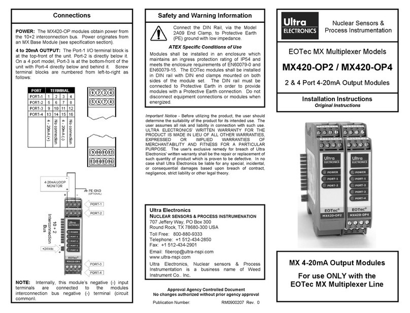
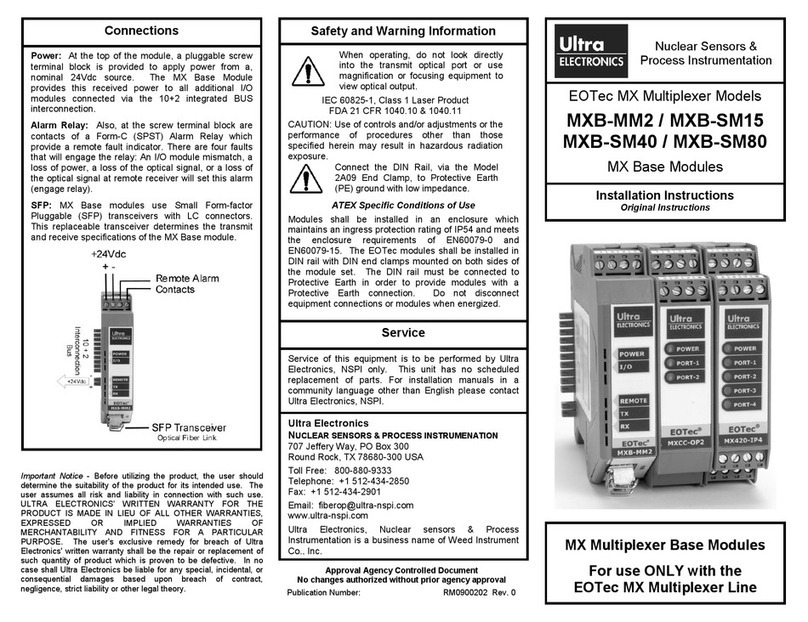
DNE Technologies
DNE TechnologiesDNE Technologies
Trunk Group Multiplexer
System POWER AGGR CLK REF PORTS FAULT
VersaMux-4000
0I
This document, and the technical data within, is controlled for export
by the United States Department of State. It, or any part thereof, may
not be exported or transferred to any foreign person either in the
United States or abroad, or disclosed to a national of another country
without the prior written approval of the United States Department of
State.
VersaMux-4000
Trunk Group Multiplexer
Operation & Installation Guide
Part No. 24001157
Revision C

Trademarks
All brand or product names are trademarks or registered trademarks of their respective companies or
organizations.
Copyright
©2007 Ultra Electronics, DNE Technologies. ALL RIGHTS RESERVED.
No part of this document may be copied, photocopied, reproduced, translated or reduced to any electronic
or machine-readable format without prior written permission of Ultra Electronics, DNE Technologies.
This document, and the technical data within, is controlled for export by the United States Department of
State. It, or any part thereof, may not be exported or transferred to any foreign person either in the United
States or abroad, or disclosed to a national of another country without the prior written approval of the
United States Department of State.
The information in this document is subject to change without notice. Ultra Electronics, DNE Technologies
assumes no responsibility for any damages arising from the use of this document, including but not limited
to, lost revenue, lost data, claims by third parties, or other damages.
Revision History
Revision Date Description
A 7/2006 First Issue
B 3/2007 Revised for Software Version 2.18. Added Fiber-Timing parameter to
Table 5-6 on page 5-21. Added note about Sync-Inhibit parameter
removal to Table 5-5 on page 5-17.
C 12/2007 Added parameter configuration notes to “Aggregate” on page 5-16 and
“Port-1, Port-2, Port-3 or Port-4” on page 5-21.

Part No. 24001157 VersaMux-4000 Operation & Installation Guide Page -iii
Revision C
Contents
Document Formats ........................................................................................... P-2
Bold Paragraph Text .................................................................................. P-2
Bold Courier Font....................................................................................... P-2
Notes......................................................................................................... P-2
Warning Formats ....................................................................................... P-2
Chapter-1 Safety Statements
Personal Safety Warnings ................................................................................. 1-3
Lightning Protection ......................................................................................... 1-4
Chapter-2 Introduction
Receiving and Inspection ................................................................................. 2-3
Receiving................................................................................................... 2-3
Inspection.................................................................................................. 2-3
Description ...................................................................................................... 2-4
Front Panel ................................................................................................ 2-4
Rear Panel.................................................................................................. 2-5
Interface Modules ...................................................................................... 2-5
Ordering Options....................................................................................... 2-6
Specifications ................................................................................................... 2-7
Supported Rates by Interface ..................................................................... 2-7
Drive Distances ......................................................................................... 2-8
Electrical.................................................................................................... 2-9
Physical ..................................................................................................... 2-9
Environmental ......................................................................................... 2-10
Chapter-3 Installation
Requirements ................................................................................................... 3-3
Mounting................................................................................................... 3-3
Temperature.............................................................................................. 3-3
Rack Mounting ................................................................................................. 3-4
Rear Support Kit ............................................................................................... 3-5
Rear Support Kit Parts List ......................................................................... 3-5
Rear Support Kit Illustrated Parts ............................................................... 3-6
Rear Support Bracket Kit Installation ................................................................ 3-8
Grounding ..................................................................................................... 3-18
Power Cord .................................................................................................... 3-19
System Interconnects ..................................................................................... 3-20
NRZ ......................................................................................................... 3-20
NRZ Control Leads ................................................................................... 3-21
NRZ DTE Operation .................................................................................. 3-22
Table of Contents T

Table of Contents
Page -iv VersaMux-4000 Operation & Installation Guide Part No. 24001157
Revision C
NRZ DCE Operation .................................................................................. 3-23
Unbalanced CDI ....................................................................................... 3-24
Control Port ............................................................................................. 3-25
Fiber Optic Connectors ............................................................................ 3-25
External Clock Input................................................................................. 3-26
Chapter-4 Getting Started
Power-Up and Basic Navigation .........................................................................4-3
Port Numbering Convention....................................................................... 4-3
Front Panel Interface .................................................................................. 4-3
Terminal Interface...................................................................................... 4-5
Planning the Timing .......................................................................................4-13
Aggregate Timing .................................................................................... 4-13
External Clock Input Timing ..................................................................... 4-15
Port Timing .............................................................................................. 4-18
Chapter-5 Operating Instructions
Main Menu .......................................................................................................5-3
Terminal Interface...................................................................................... 5-3
Front Panel Interface .................................................................................. 5-4
Alarm-Status .....................................................................................................5-5
Terminal Interface...................................................................................... 5-6
Front Panel Interface .................................................................................. 5-7
Configure .........................................................................................................5-8
Terminal Interface...................................................................................... 5-8
Front Panel Interface .................................................................................. 5-9
System....................................................................................................... 5-9
Offline ..................................................................................................... 5-14
Active ...................................................................................................... 5-24
CAU ......................................................................................................... 5-27
Management ............................................................................................ 5-31
Activate ..........................................................................................................5-34
Terminal Interface.................................................................................... 5-35
Front Panel Interface ................................................................................ 5-35
System-Info ....................................................................................................5-36
Conditions ............................................................................................... 5-36
Inventory ................................................................................................. 5-36
Terminal Interface.................................................................................... 5-37
Front Panel Interface ................................................................................ 5-41
Statistics ........................................................................................................5-42
Front Panel Interface ................................................................................ 5-42
Terminal Interface.................................................................................... 5-43
Alarm-Stats .............................................................................................. 5-44
Aggregate-Stats ....................................................................................... 5-44
Bandwidth-Stats ....................................................................................... 5-45
Chapter-6 Diagnostics
LED Indicators ..................................................................................................6-3
LED Descriptions........................................................................................ 6-3
LED States.................................................................................................. 6-5
Diagnostics Menu .............................................................................................6-6

Table of Contents
Part No. 24001157 VersaMux-4000 Operation & Installation Guide Page -v
Revision C
Terminal Interface ..................................................................................... 6-6
Front Panel Interface.................................................................................. 6-7
Loopbacks ................................................................................................. 6-7
BERT ........................................................................................................ 6-11
Hot-swap ................................................................................................. 6-15
Test ......................................................................................................... 6-17
Chapter-7 Maintenance
Preventive Maintenance ................................................................................... 7-3
Cleaning Electrical Connectors................................................................... 7-3
Cleaning Optical Connectors...................................................................... 7-3
Replacing/Installing a Module .......................................................................... 7-5
Hot-Swapping a Module ............................................................................. 7-5
Removing a Module ................................................................................... 7-6
Installing a module .................................................................................... 7-7
Procedure .................................................................................................. 7-9
Software Upgrade Procedure .......................................................................... 7-10
Chapter-8 Warranty Statements
Statement of Warranty ...................................................................................... 8-3
Service Requests .............................................................................................. 8-4
Returning Defective Equipment ........................................................................ 8-5
Obtaining an RMA and Returning Equipment.............................................. 8-5
Preparing Items for Return......................................................................... 8-5

Table of Contents
Page -vi VersaMux-4000 Operation & Installation Guide Part No. 24001157
Revision C

Preface
Part No. 24001157 VersaMux-4000 Operation & Installation Guide Page P-1
Revision C
Preface P
About this Document
This manual provides a description, installation and operating instructions, and
troubleshooting and maintenance procedures for the DNE Technologies VersaMux-
4000 Trunk Group Multiplexer. Topics covered in this manual include:
• General description, features and specifications
• Unpacking, inspection, and installation
• Unit hardware configuration
• Equipment operating instructions
• System diagnostics and tests
• Maintenance
• Warranty statements
This document is available as an Adobe PDF on the VersaMux-4000 CDROM,
DNE Part Number 24001158 or via the Ultra Electronics, DNE Technologies web
site (http://www.ultra-dne.com). Note that the web site requires registration and is
subject to ITAR regulations.

Document Formats Preface
Page P-2 VersaMux-4000 Operation & Installation Guide Part No. 24001157
Revision C
Document Formats
This section briefly describes the use of fonts (type faces), styles, and symbols,
used throughout this document.
Bold Paragraph
Text
Bold text in the document body text represents names and symbols that appear on
the user interface screens. For example:
•SelectAdministration from the Main Menu.
The System Administration screen appears.
In this example “Administration” is a parameter on a screen and “Main Menu”
and “System Administration“ are screen titles that appear on the screens.
Bold Courier Font Courier font, also referred to as “typewriter font” appears in this document as
something you type into the User Interface. For example:
• Type the following into the field:
connect1
where “connect1” is what you actually type.
Notes Important information and tips appear as notes. Notes have a special format and
appearance. The following is an example of the Note format:
NOTE: This is how a note appears in this document.
Warning Formats This document may use warnings for various potential conditions. The following
are the warning formats with descriptions of their use:
WARNING: This format is used for an electrical danger that may Injure
or kill the user.

Preface Document Formats
Part No. 24001157 VersaMux-4000 Operation & Installation Guide Page P-3
Revision C
WARNING: This format is used for a hazardous condition that may
cause personal Injury to the user.
DANGER: This format is used for a condition that is potentially fatal.
CAUTION: This format is used for a condition that may damage
equipment but the personal injury risk is low.

Document Formats Preface
Page P-4 VersaMux-4000 Operation & Installation Guide Part No. 24001157
Revision C
This page intentionally left blank.

Part No. 24001157 VersaMux-4000 Operation & Installation Guide Page 1-1
Revision C
Chapter
Safety Statements 1
About this Chapter This chapter provides important safety information. You must become familiar
with this information before installing and operating the VersaMux-4000.
Chapter Contents This chapter contains the following topics:
Personal Safety Warnings ................................................................................ 1-3
Lightning Protection ........................................................................................ 1-4

Chapter 1: Safety Statements
Page 1-2 VersaMux-4000 Operation & Installation Guide Part No. 24001157
Revision C
Do not try to pull or grab the individual.
If possible, turn off the electrical power.
If you cannot turn off the electrical power,
pull, push or lift the person to safety using
a dry wooden pole or a dry rope or some
other insulating material.
Send for help as soon as possible.
After the injured person is free of contact
with the source of electrical shock, move
the person a short distance away and
immediately start artificial resuscitation.
Refer to FM 21-11.
Safety steps to follow if someone is the victim of electrical shock.
1
2
3
4
5

Chapter 1: Safety Statements Personal Safety Warnings
Part No. 24001157 VersaMux-4000 Operation & Installation Guide Page 1-3
Revision C
Personal Safety Warnings
WARNING HIGH VOLTAGE: High voltage is used in the operation of this
equipment. Be careful when working near AC power distribution. Observe
warning notes in this technical manual and warning decals on equipment.
Death on contact may result if safety precautions are not observed. Never
work on electronic equipment unless there is another person nearby who is
familiar with the operation and hazards of the equipment and who is
competent in administering first aid. When the technicians are aided by
operators, they must be warned about dangerous areas. Whenever
possible, the power supply to the equipment must be shut off before
beginning work on the equipment.
WARNING: Be careful not to contact high-voltage connections or AC input
connections when installing or operating this equipment.
WARNING: Whenever the nature of the operation permits, keep one hand
away from the equipment to reduce the hazard of current flowing through
the body.
WARNING: Do not be misled by the term “low voltage.” Potentials as low
as 50 volts may cause death under adverse conditions.
WARNING: To avoid electrical shock and damage to equipment, be certain
POWER ON/OFF switch is set to OFF and power cable is disconnected at
power source before disconnecting signal cables.

Lightning Protection Chapter 1: Safety Statements
Page 1-4 VersaMux-4000 Operation & Installation Guide Part No. 24001157
Revision C
Lightning Protection
WARNING: CDI inputs/outputs are protected against indirect lightning
strikes provided sufficient earth grounding is established.
When using this product, it is recommended that the chassis be directly
connected to a good earth ground using an appropriate cable as described
in “Grounding” on page 3-18.

Part No. 24001157 VersaMux-4000 Operation & Installation Guide Page 2-1
Revision C
Chapter
Introduction 2
About this Chapter This chapter provides a description and the specifications for the VersaMux-4000
Trunk Group Multiplexer as well as receiving and inspection information.
Chapter Contents This chapter contains the following topics:
Receiving and Inspection ................................................................................ 2-3
Receiving ............................................................................................... 2-3
Inspection ............................................................................................. 2-3
Description ..................................................................................................... 2-4
Front Panel ............................................................................................ 2-4
Rear Panel ............................................................................................. 2-5
Interface Modules .................................................................................. 2-5
Ordering Options ................................................................................... 2-6
Specifications .................................................................................................. 2-7
Supported Rates by Interface ................................................................. 2-7
Drive Distances ..................................................................................... 2-8
Electrical ................................................................................................ 2-9
Physical ................................................................................................. 2-9
Environmental ..................................................................................... 2-10

Chapter 2: Introduction
Page 2-2 VersaMux-4000 Operation & Installation Guide Part No. 24001157
Revision C
This page intentionally left blank

Chapter 2: Introduction Receiving and Inspection
Part No. 24001157 VersaMux-4000 Operation & Installation Guide Page 2-3
Revision C
Receiving and Inspection
Receiving Inspect the shipping container for damage that may indicate damage to the
VersaMux-4000. Packing and crating materials should be retained for storage or
shipment.
Inspection After unpacking the VersaMux-4000, the unit should be inspected for damage.
Perform a visual inspection and check for damaged hardware or dents on the
chassis assembly. If damage occurred during transit, contact the carrier
immediately for disposition.
WARNING: The VersaMux-4000 contains no user serviceable internal parts.
Do not remove the VersaMux-4000 cover.

Description Chapter 2: Introduction
Page 2-4 VersaMux-4000 Operation & Installation Guide Part No. 24001157
Revision C
Description
The VersaMux-4000 extends the current DNE CV product line by providing the
ability to multiplex up to four ports of trunk group traffic onto a single aggregate
channel for transport to a remote site. The VersaMux-4000 provides aggregate
speeds up to 16-Mbps for use with modern high-speed radio and satellite
equipment. The aggregate utilizes a highly efficient time division multiplexing
(TDM) algorithm derived from the DNE AN/FCC-100 product line.
The VersaMux-4000 system consists of a base chassis that contains five interface
slots (four user slots and one aggregate), external (station) clock input, control
(craft) port, AC power input, and the front panel control interface. Interface
modules populate the slot positions within the base chassis to meet specific
customer requirements. The VersaMux-4000 mounts in a standard 19” rack or can
operate as a “table-top” unit. Version 1.0 supports only the NRZ aggregate module
and the Combo Fiber-Copper (user input) Modules.
The VersaMux-4000 provides circuit level modularity providing you with
convenient upgrade and maintenance procedures while maintaining live
operational links. The modular architecture also provides sparing capability for
each interface. The VersaMux-4000 supports interoperability with all existing CV
product line interfaces as well as JTC3A-9109 compliant equipment such as the
AN/GSC-54 and MD-1272. In addition to operating with converter products, the
VersaMux-4000 is interoperable with NRZ-based serial data equipment.
Hot Swap
The VersaMux-4000 modules are “hot swappable.” The interface modules can be
replaced with another supported interface module without powering down the
system. User interface modules can be “hot-swapped” without losing the other
active user links. See “Hot-swap” on page 6-15.
Flash Memory
All VersaMux-4000 models store configuration information in flash memory. This
enables the VersaMux-4000 to maintain the configuration through power cycles.
Front Panel The front panel of the VersaMux-4000 chassis provides an on/off switch, front
panel display with keypad, and status LED indicators as shown in Figure 2-1.
Figure 2-1 VersaMux-4000 Front Panel
System POWER AGGR CLK REF PORTS FAULT
VersaMux-4000
0I

Chapter 2: Introduction Description
Part No. 24001157 VersaMux-4000 Operation & Installation Guide Page 2-5
Revision C
Rear Panel The VersaMux-4000 chassis is capable of accepting up to five interface modules
(one aggregate module and up to four user input modules). The module slots are
located on the rear panel of the chassis along with a craft (control) port, an
external clock input (BNC connector), and a grounding post as shown in
Figure 2-2.
Figure 2-2 VersaMux-4000 Rear Panel (Fully Populated- DNE Part Number 97680100)
Interface Modules Figure 2-3 shows a straight-on view of the NRZ Aggregate Module.
Figure 2-3 VersaMux-4000 NRZ Aggregate Module
Figure 2-4 shows a straight-on view of the Combo Fiber-Copper Module.
Figure 2-4 Versamux-4000 Combo Fiber-Copper Module
EXT CLK
FIBER / CU
FRX CRX FTX CTX
FIBER / CU
FRX CRX FTX CTX
FIBER / CU
FRX CRX FTX CTX
FIBER / CU
FRX CRX FTX CTX
NRZ
NRZ
FIBER / CU
FRX CRX FTX CTX

Description Chapter 2: Introduction
Page 2-6 VersaMux-4000 Operation & Installation Guide Part No. 24001157
Revision C
Ordering Options Tab le 2- 1 lists the VersaMux-4000 ordering options.
Table 2-1 VersaMux-4000 Ordering Options
Part Number Description
97680100 Versamux-4000 system. Includes a VersaMux-4000 Base Chassis,
4 Combo Modules, and an NRZ Aggregate Module
97680001 Versamux-4000 Chassis
97680008 Versamux-4000 Combo Fiber-Copper Module
97680003 Versamux-4000 NRZ Aggregate Module
24001157-000 Optional/Replacement Printed & Bound VersaMux-4000 User Guide
(latest revision).
24001158-000 Optional/Replacement VersaMux-4000 User Guide on CD (latest revision).
61060214 Optional Blank Port Cover Plate. Use this plate to cover the chassis opening when
you “permanently” remove a port module from the VersaMux-4000 chassis.
Table 2-1
Table of contents
Other Ultra electronics Multiplexer manuals