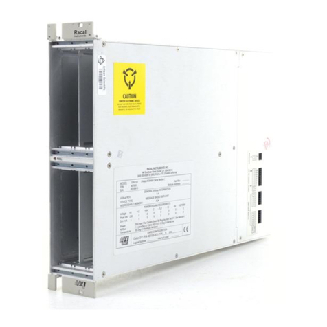
Racal Instruments 1260-30 Series User manual

Artisan Technology Group is your source for quality
new and certied-used/pre-owned equipment
• FAST SHIPPING AND
DELIVERY
• TENS OF THOUSANDS OF
IN-STOCK ITEMS
• EQUIPMENT DEMOS
• HUNDREDS OF
MANUFACTURERS
SUPPORTED
• LEASING/MONTHLY
RENTALS
• ITAR CERTIFIED
SECURE ASSET SOLUTIONS
SERVICE CENTER REPAIRS
Experienced engineers and technicians on staff
at our full-service, in-house repair center
WE BUY USED EQUIPMENT
Sell your excess, underutilized, and idle used equipment
We also offer credit for buy-backs and trade-ins
www.artisantg.com/WeBuyEquipment
REMOTE INSPECTION
Remotely inspect equipment before purchasing with
our interactive website at www.instraview.com
LOOKING FOR MORE INFORMATION?
Visit us on the web at www.artisantg.com for more
information on price quotations, drivers, technical
specications, manuals, and documentation
Contact us: (888) 88-SOURCE | sales@artisantg.com | www.artisantg.com
SM
View
Instra

1260 VXI
SWITCHING CARD
1260-30
SIGNAL / MULTIPLEXER
PUBLICATION NO. 980673-005
RACAL INSTRUMENTS
Racal Instruments, Inc.
4 Goodyear St., Irvine, CA 92618-2002
Tel: (800) 722-3262, FAX: (949) 859-7309
Racal Instruments, Ltd.
480 Bath Road, Slough, Berkshire, SL1 6BE, United Kingdom
Tel: +44 (0) 8706 080134; FAX: +44 (0) 1753 791290
Racal Systems Electronique S.A.
18 Avenue Dutartre, 78150 LeChesnay, France
Tel: +33 (1) 3923 2222; FAX: +33 (1) 3923 2225
Racal Systems Elettronica s.r.l.
Strada 2-Palazzo C4, 20090 Milanofiori Assago, Milan, Italy
Tel: +39 (02) 5750 1796; FAX +39 (02) 5750 1828
Racal Elektronik System GmbH.
Frankenforster Strasse 21, 51427 Bergisch Gladbach, Germany
Tel:+49 2204 92220; FAX: +49 2204 21491
Racal Australia Pty. Ltd.
3 Powells Road, Brookvale, NSW 2100, Australia
Tel: +61 (2) 9936 7000, FAX: +61 (2) 9936 7036
Racal Electronics Pte. Ltd.
26 Ayer Rajah Crescent, 04-06/07 Ayer Rajah Industrial Estate, Singapore 0513.
Tel: +65 7792200, FAX: +65 7785400
Racal Instruments, Ltd.
Unit 5, 25F., Mega Trade Center, No 1, Mei Wan Road, Tsuen Wan, Hong Kong, PRC
Tel: +852 2405 5500, FAX: +852 2416 4335
http://www.racalinst.com
PUBLICATION DATE: April 6, 2000
Copyright 1997 by Racal Instruments, Inc. Printed in the United States of America. All rights reserved.
This book or parts thereof may not be reproduced in any form without written permission of the publisher.
Artisan Technology Group - Quality Instrumentation ... Guaranteed | (888) 88-SOURCE | www.artisantg.com

WARRANTY STATEMENT
All Racal Instruments, Inc. products are designed and manufactured to exacting standards and in full
conformance to Racal’s ISO 9001 procedures.
For the specific terms of your standard warranty, or optional extended warranty or service agreement, contact
your Racal customer service advisor. Please have the following information available to facilitate service.
1. Product serial number
2. Product model number
3. Your company and contact information
You may contact your customer service advisor by:
E-Mail: [email protected]
Telephone: +1 800 722 3262 (USA)
+44(0) 8706 080134 (UK)
+852 2405 5500 (Hong Kong)
Fax: +1 949 859 7309 (USA)
+44(0) 1628 662017 (UK)
+852 2416 4335 (Hong Kong)
RETURN of PRODUCT
Authorization is required from Racal Instruments before you send us your product for service or calibration. Call
your nearest Racal Instruments support facility. A list is located on the last page of this manual. If you are
unsure where to call, contact Racal Instruments, Inc. Customer Support Department in Irvine, California, USA at
1-800-722-3262 or 1-949-859-8999 or via fax at 1-949-859-7139. We can be reached at:
PROPRIETARY NOTICE
This document and the technical data herein disclosed, are proprietary to Racal Instruments, and shall not,
without express written permission of Racal Instruments, be used, in whole or in part to solicit quotations from a
competitive source or used for manufacture by anyone other than Racal Instruments. The information herein has
been developed at private expense, and may only be used for operation and maintenance reference purposes or
for purposes of engineering evaluation and incorporation into technical specifications and other documents which
specify procurement of products from Racal Instruments.
Artisan Technology Group - Quality Instrumentation ... Guaranteed | (888) 88-SOURCE | www.artisantg.com

FOR YOUR SAFETY
Before undertaking any troubleshooting, maintenance or exploratory procedure, read carefully the
WARNINGS and CAUTION notices.
This equipment contains voltage hazardous to human life and safety, and is capable of inflicting
personal injury.
If this instrument is to be powered from the AC line (mains) through an autotransformer, ensure the
common connector is connected to the neutral (earth pole) of the power supply.
Before operating the unit, ensure the conductor (green wire) is connected to the ground (earth)
conductor of the power outlet. Do not use a two-conductor extension cord or a three-prong/two-
prong adapter. This will defeat the protective feature of the third conductor in the power cord.
Maintenance and calibration procedures sometimes call for operation of the unit with power applied
and protective covers removed. Read the procedures and heed warnings to avoid “live” circuit
points.
Before operating this instrument:
1. Ensure the instrument is configured to operate on the voltage at the power source. See
Installation Section.
2. Ensure the proper fuse is in place for the power source to operate.
3. Ensure all other devices connected to or in proximity to this instrument are properly grounded or
connected to the protective third-wire earth ground.
If the instrument:
-fails to operate satisfactorily
-shows visible damage
-has been stored under unfavorable conditions
-has sustained stress
Do not operate until performance is checked by qualified personnel.
Artisan Technology Group - Quality Instrumentation ... Guaranteed | (888) 88-SOURCE | www.artisantg.com

This page was left intentionally blank.
Artisan Technology Group - Quality Instrumentation ... Guaranteed | (888) 88-SOURCE | www.artisantg.com

Amendment Page 6/98 1
NOTE FOR SYSTEMS WITH 1260-OPT 01T
The “Module-Specific Syntax” section of this manual shows the command syntax for the
1260-01S Smart Card. If you are using the newer 1260-01T Smart Card, the commands
will NOT work as shown.
Consult the 1260-01T Manual for a description of the commands that may be used with the
1260-01T Smart Card.
The channel numbers described in this manual are valid for the 1260-01T. The channel
numbers continue to be used for the 1260-01T.
The syntax of the commands that use channel numbers has changed for those cards
controlled by the 1260-01T.
The new syntax used to close a channel is:
CLOSE (@ <module address> ( <channel> ) )
For example, for a relay module whose <module address> is set to 7, closing <channel> 0
is performed with the command:
CLOSE (@7 (0))
Using the older 1260-01S, the command would be (as shown in this manual):
CLOSE 7.0
Many other command syntax differences exist. Please consult chapter 2 of the 1260-01T
manual for a description of the commands that are available for the 1260-01T.
Artisan Technology Group - Quality Instrumentation ... Guaranteed | (888) 88-SOURCE | www.artisantg.com

Control Information for the 1260-30A
The following information describes the control-register-to-relay-channel mapping for a 1260-30A Relay
Module. This information may be used to control a 1260-30A when using a 1260-01T in the register-based
mode of operation.
Each relay on this module is controlled by setting or clearing a single bit within a Control Register. Control
Registers on the module operate 8 channels simultaneously. There are eight control bits per Control Register.
Setting the bit to a 1 closes the relay; setting the bit to a 0 opens the relay.
The table below shows the mapping from logical channels to control bits. The logical channels are used when
operating the relay module in message-based mode. The control bits within the Control Registers are used to
operate the module in register-based mode.
Each Control Register is located 2 addresses from the previous Control Register. That is, each Control
Register is located at an odd address. This is shown in Table 2-2 of the 1260-01T manual. Control Register 0
is located at the “Base A24 Address” for the module. Consult the “Register-Based Operation” Section of
Chapter 2 of the 1260-01T manual for a description of calculating control register addresses
Channel Control Register Control Bit
000
101
202
303
404
505
606
707
810
911
10 1 2
11 1 3
12 1 4
13 1 5
14 1 6
15 1 7
16 2 0
17 2 1
18 2 2
19 2 3
20 2 4
21 2 5
22 2 6
23 2 7
24 3 0
25 3 1
26 3 2
27 3 3
28 3 4
29 3 5
30 3 6
31 3 7
32 4 0
33 4 1
34 4 2
35 4 3
36 4 4
37 4 5
38 4 6
39 4 7
Artisan Technology Group - Quality Instrumentation ... Guaranteed | (888) 88-SOURCE | www.artisantg.com

Control Information for the 1260-30B
The following information describes the control-register-to-relay-channel mapping for a 1260-30B Relay
Module. This information may be used to control a 1260-30B when using a 1260-01T in the register-based
mode of operation.
Each relay on this module is controlled by setting or clearing a single bit within a Control Register. Control
Registers on the module operate 8 channels simultaneously. There are eight control bits per Control Register.
Setting the bit to a 1 closes the relay; setting the bit to a 0 opens the relay.
The table below shows the mapping from logical channels to control bits. The logical channels are used when
operating the relay module in message-based mode. The control bits within the Control Registers are used to
operate the module in register-based mode.
Each Control Register is located 2 addresses from the previous Control Register. That is, each Control
Register is located at an odd address. This is shown in Table 2-2 of the 1260-01T manual. Control Register 0
is located at the “Base A24 Address” for the module. Consult the “Register-Based Operation” Section of
Chapter 2 of the 1260-01T manual for a description of calculating control register addresses
Channel Control Register Control Bit
000
101
202
303
404
505
606
707
810
911
10 1 2
11 1 3
12 1 4
13 1 5
14 1 6
15 1 7
16 2 0
17 2 1
18 2 2
19 2 3
100 2 4
101 2 5
102 2 6
103 2 7
104 3 0
105 3 1
106 3 2
107 3 3
108 3 4
109 3 5
110 3 6
111 3 7
112 4 0
113 4 1
114 4 2
115 4 3
116 4 4
117 4 5
118 4 6
119 4 7
Artisan Technology Group - Quality Instrumentation ... Guaranteed | (888) 88-SOURCE | www.artisantg.com

Control Information for the 1260-30C
The following information describes the control-register-to-relay-channel mapping for a 1260-30C Relay
Module. This information may be used to control a 1260-30C when using a 1260-01T in the register-based
mode of operation.
Each relay on this module is controlled by setting or clearing a single bit within a Control Register. Control
Registers on the module operate 8 channels simultaneously. There are eight control bits per Control Register.
Setting the bit to a 1 closes the relay; setting the bit to a 0 opens the relay.
The table below shows the mapping from logical channels to control bits. The logical channels are used when
operating the relay module in message-based mode. The control bits within the Control Registers are used to
operate the module in register-based mode.
Each Control Register is located 2 addresses from the previous Control Register. That is, each Control
Register is located at an odd address. This is shown in Table 2-2 of the 1260-01T manual. Control Register 0
is located at the “Base A24 Address” for the module. Consult the “Register-Based Operation” Section of
Chapter 2 of the 1260-01T manual for a description of calculating control register addresses
Channel Control Register Control Bit
000
101
202
303
404
505
606
707
810
911
100 1 2
101 1 3
102 1 4
103 1 5
104 1 6
105 1 7
106 2 0
107 2 1
108 2 2
109 2 3
200 2 4
201 2 5
202 2 6
203 2 7
204 3 0
205 3 1
206 3 2
207 3 3
208 3 4
209 3 5
300 3 6
301 3 7
302 4 0
303 4 1
304 4 2
305 4 3
306 4 4
307 4 5
308 4 6
309 4 7
Artisan Technology Group - Quality Instrumentation ... Guaranteed | (888) 88-SOURCE | www.artisantg.com

Control Information for the 1260-30D
The following information describes the control-register-to-relay-channel mapping for a 1260-30D Relay
Module. This information may be used to control a 1260-30D when using a 1260-01T in the register-based
mode of operation.
Each relay on this module is controlled by setting or clearing a single bit within a Control Register. Control
Registers on the module operate 8 channels simultaneously. There are eight control bits per Control Register.
Setting the bit to a 1 closes the relay; setting the bit to a 0 opens the relay.
The table below shows the mapping from logical channels to control bits. The logical channels are used when
operating the relay module in message-based mode. The control bits within the Control Registers are used to
operate the module in register-based mode.
Each Control Register is located 2 addresses from the previous Control Register. That is, each Control
Register is located at an odd address. This is shown in Table 2-2 of the 1260-01T manual. Control Register 0
is located at the “Base A24 Address” for the module. Consult the “Register-Based Operation” Section of
Chapter 2 of the 1260-01T manual for a description of calculating control register addresses
Channel Control Register Control Bit
000
101
202
303
404
100 0 5
101 0 6
102 0 7
103 1 0
104 1 1
200 1 2
201 1 3
202 1 4
203 1 5
204 1 6
300 1 7
301 2 0
302 2 1
303 2 2
304 2 3
400 2 4
401 2 5
402 2 6
403 2 7
404 3 0
500 3 1
501 3 2
502 3 3
503 3 4
504 3 5
600 3 6
601 3 7
602 4 0
603 4 1
604 4 2
700 4 3
701 4 4
702 4 5
703 4 6
704 4 7
Artisan Technology Group - Quality Instrumentation ... Guaranteed | (888) 88-SOURCE | www.artisantg.com

User Manual 1260-30
i
Table of Contents
Chapter 1
MODULE SPECIFICATION.......................................................................................................... 1-1
1260-30 Module Specification...................................................................................................1-1
Specifications ........................................................................................................................1-2
DC Performance................................................................................................................ 1-2
AC Performance ................................................................................................................ 1-2
General.............................................................................................................................. 1-3
Minimum Option 01 Firmware ............................................................................................ 1-3
Ordering Information.................................................................................................................1-3
Safety........................................................................................................................................ 1-3
Product Support........................................................................................................................1-3
Chapter 2
INSTALLATION INSTRUCTIONS ................................................................................................ 2-1
Unpacking and Inspection.........................................................................................................2-1
Reshipment Instructions............................................................................................................2-1
Option 01 Installation ................................................................................................................2-2
Module Installation .................................................................................................................... 2-2
Configuration Settings ........................................................................................................... 2-2
1260-30A ...........................................................................................................................2-3
1260-30B ...........................................................................................................................2-4
1260-30C...........................................................................................................................2-5
1260-30D...........................................................................................................................2-6
1260-30 ID Byte..................................................................................................................... 2-7
Chapter 3
MODULE SPECIFIC SYNTAX...................................................................................................... 3-1
1260-30 Module Specific Syntax...............................................................................................3-1
Syntax ...................................................................................................................................3-1
CLOSE Command.................................................................................................................3-2
PSETUP Command............................................................................................................... 3-2
PDATAOUT Command.......................................................................................................... 3-3
Artisan Technology Group - Quality Instrumentation ... Guaranteed | (888) 88-SOURCE | www.artisantg.com

User Manual 1260-30
ii
Chapter 4
DRAWINGS ................................................................................................................................. 4-1
Chapter 5
PARTS LIST................................................................................................................................. 5-1
Chapter
OPTIONAL HARNESS ASSEMBLIES.......................................................................................... 6-1
Chapter 7
PRODUCT SUPPORT ................................................................................................................. 7-1
Product Support........................................................................................................................ 7-1
Reshipment Instructions ........................................................................................................... 7-1
Support Offices......................................................................................................................... 7-2
Artisan Technology Group - Quality Instrumentation ... Guaranteed | (888) 88-SOURCE | www.artisantg.com

User Manual 1260-30
iii
List of Figures
Figure 1-1, 1260-30 Signal/Multiplexer Scanner Module............................................................... 1-1
Figure 1-2, 1260-30 Relay Matrix.................................................................................................. 1-2
Figure 3-1, 1260-30 J200 and J201 Connector Pin Configuration ................................................3-5
Figure 3-2, 1260-30 Configurations and Command Codes........................................................... 3-6
Figure 3-2, 1260-30 Configurations and Command Codes (continued)........................................3-7
Artisan Technology Group - Quality Instrumentation ... Guaranteed | (888) 88-SOURCE | www.artisantg.com

User Manual 1260-30
iv
This page was left intentionally blank.
Artisan Technology Group - Quality Instrumentation ... Guaranteed | (888) 88-SOURCE | www.artisantg.com

User Manual 1260-30
Module Specification 1-1
Chapter 1
MODULE SPECIFICATION
1260-30 Module
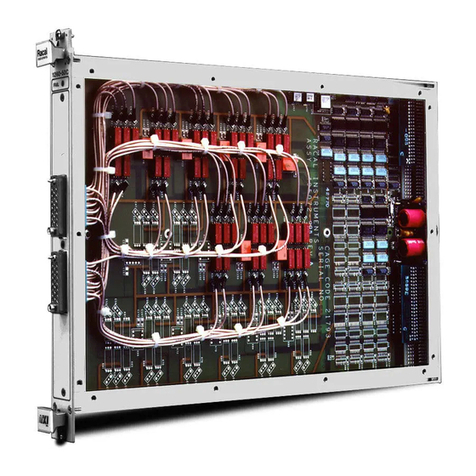
Specification The 1260-30 Signal/Multiplexer Scanner Module is a 1 X 40
multiplexer. It switches two lines per channel, and has the
capability of being configured as two 1 X 20 matrices, four 1 X 10
matrices or eight 1 X 5 matrices (refer to the diagram in Figure 1-
2).
Figure 1-1, 1260-30 Signal/Multiplexer Scanner Module
Artisan Technology Group - Quality Instrumentation ... Guaranteed | (888) 88-SOURCE | www.artisantg.com

User Manual 1260-30
Module Specification 1-2
Figure 1-2, 1260-30 Relay Matrix
Specifications Maximum Switchable Voltage 220VDC, 250VAC RMS
(Terminal-Terminal or Terminal-Chassis
Maximum Switchable Current 2A DC or RMS
Maximum Switchable Power
Per Channel 60W DC, 62.5VA AC
DC Performance Isolation >109Ω
AC Performance Capacitance
Open Channel < 40pF
Channel-Chassis < 60pF
Hi-Lo < 280pF
Bandwidth (-3dB, 50Ω) 10MHz (Typical)
Insertion Loss (50Ω) < 0.1dB @ 100kHz
< 0.1db @ 1MHz
< 1.3dB @ 10MHz
Crosstalk (50Ω) < -55dB @ 100kHz
< -45dB @ 1MHz
< -30dB @ 10MHz
Com1
J1 Com2
J2 Com3
J3 Com4
J4 Com5
J5 Com 6
J6 Com7
J7 Com8
Com1
Artisan Technology Group - Quality Instrumentation ... Guaranteed | (888) 88-SOURCE | www.artisantg.com

User Manual 1260-30
Module Specification 1-3
General Cooling
Airflow Backpressure 4.0 liters/sec, 0.5mm H20
Power Requirements
+5V, Ipm 0.4A (2.8A with Option 01 installed)
+24V, Idm 10mA per energized relay
User Connector SMPL 4 FOTO LB
Weight 2.59lbs (1.17Kg)
2.87lbs (1.29Kg) with Option 01
Minimum Option 01
Firmware Revision 17.1
Ordering
Information
Model Number
1260-30A
1260-30B
1260-30C
1260-30D
Description
2-wire, One, 1x40 Multiplexer
2-wire, Two, 1x20 Multiplexer
2-wire, Four, 1x10 Multiplexer
2-wire, Eight, 1x5 Multiplexer
Part Number
404767-001
404767-002
404767-003
404767-004
Safety Refer to the “FOR YOUR SAFETY” page preceding the Table of
Contents. Following all NOTES, CAUTIONS, and WARNINGS to
ensure personal safety and prevent damage to the instrument.
Product Support Racal Instruments has a complete Service and Parts Department.
If you need technical assistance or should it be necessary to return
your product for servicing, call 1-800-722-3262. If parts are
required to repair the product at your facility, call 1-949-859-8999
and ask for the Parts Department
When sending your instrument in for repair, complete the form in
the back of this manual.
Artisan Technology Group - Quality Instrumentation ... Guaranteed | (888) 88-SOURCE | www.artisantg.com

User Manual 1260-30
Module Specification 1-4
This page was left intentionally blank.
Artisan Technology Group - Quality Instrumentation ... Guaranteed | (888) 88-SOURCE | www.artisantg.com

User Manual 1260-30
Installation Instructions 2-1
Chapter 2
INSTALLATION INSTRUCTIONS
Unpacking and
Inspection 1.Before unpacking the switching module, check the exterior of
the shipping carton for any signs of damage. All irregularities
should be noted on the shipping bill.
2.Remove the instrument from its carton, preserving the factory
packaging as much as possible. Inspect the switching module
for any defect or damage
3.Immediately notify the carrier if any damage is apparent.
4.Have a qualified person check the instrument for safety before
use.
CAUTION
Proper ESD handling procedures must always be
used when packing, unpacking or installing any 1260
Series cards. Failure to do so may cause damage to
the unit.
Reshipment
Instructions 1.Use the original packing material when returning the switching
module to Racal Instruments for servicing. The original
shipping carton and the instrument's plastic foam will provide
the necessary support for safe reshipment.
2.If the original packing material is unavailable, wrap the
switching module in plastic sheeting and use plastic spray
foam to surround and protect the instrument.
3.Reship in either the original or a new shipping carton.
Artisan Technology Group - Quality Instrumentation ... Guaranteed | (888) 88-SOURCE | www.artisantg.com

User Manual 1260-30
Installation Instructions 2-2
Option 01
Installation Installation of the Option 01 into the 1260-30 is described in the
Installation section of the 1260 Series VXI Switching Cards
Manual.
Module
Installation Installation of the 1260-30 Switching Module into a VXI mainframe,
including the setting of DIP switches, is described in the
Installation section of the 1260 Series VXI Switching Cards
Manual. Configuration of the PCBA and setting DIP switches
SW1-5 and SW1-6 are described in the following sections.
Configuration
Settings
The 1260-30 is configurable as 1x40, two 1x20, four 1x10, or eight
1x5 multiplexers. The configuration is set by the installation of 24
gage jumpers to the board as follows:
Model
1260-30A
1260-30B
1260-30C
1260-30D
Configuration
One 1X40
Two 1X20
Four 1X10
Eight 1X5
Jumpers
All
J1, J2, J3, J5, J6. and J7
J1, J3, J5, and J7
None
Note this illustrates the principle of the 1260-30 configuration
setting. The connections to be made on the PCB are given on the
following pages.
Artisan Technology Group - Quality Instrumentation ... Guaranteed | (888) 88-SOURCE | www.artisantg.com
This manual suits for next models
4
Table of contents
Other Racal Instruments Multiplexer manuals

Racal Instruments
Racal Instruments 1260-50C User manual

Racal Instruments
Racal Instruments 1260-112 User manual

Racal Instruments
Racal Instruments 1260-X133 User manual

Racal Instruments
Racal Instruments 1260-100X X Series User manual

Racal Instruments
Racal Instruments MULTIPLEXER PLUG-IN 1260-134 User manual

Racal Instruments
Racal Instruments 1260-38T User manual
Racal Instruments
Racal Instruments 1260 VXI User manual